Dell Edge Gateway 5000 Series Installation And Operation Manual
Hide thumbs
Also See for Edge Gateway 5000 Series:
- Service manual (49 pages) ,
- Quick start manual (2 pages)
Table of Contents
Advertisement
Quick Links
See also:
Service Manual
Advertisement
Table of Contents

Subscribe to Our Youtube Channel
Related Manuals for Dell Edge Gateway 5000 Series


Summary of Contents for Dell Edge Gateway 5000 Series
-
Page 1: Installation And Operation Manual
Dell Edge Gateway 5000 Series Installation and Operation Manual Computer Model: Dell Edge Gateway 5000\5100 Regulatory Model: N01G\N02G Regulatory Type: N01G001\N02G001... - Page 2 © 2016 Dell Inc. All rights reserved. This product is protected by U.S. and international copyright and intellectual property laws. Dell and the Dell logo are trademarks of Dell Inc. in the United States and/or other jurisdictions. All other marks and names mentioned herein may be trademarks of their respective companies.
-
Page 3: Table Of Contents
Powering on the Dell Edge Gateway .......... 16 Mounting the Dell Edge Gateway on the wall ........19 Mounting the Dell Edge Gateway on a DIN rail ..21 Inserting a micro-SIM card and activating your mobile broadband ................23 Removing the micro-SIM card Setting up your operating system.......... - Page 4 Setting up the Power Module ........... 46 Power module — Connecting a battery ...............48 Specifications - Power Module Enclosure Overview..............51 ......................51 Features ................. 53 Setting up the Enclosure ................60 Specifications - Enclosure Setting up the ZigBee Dongle ..........62 Contacting Dell................64...
-
Page 5: Overview
The system can be either mounted on the wall using the Dell approved wall mount kit or mounted into your existing rack infrastructure using the DIN-rail mounting bracket. The system is running on Windows 10 Enterprise, Ubuntu Snappy, and Wind River Linux operating systems. -
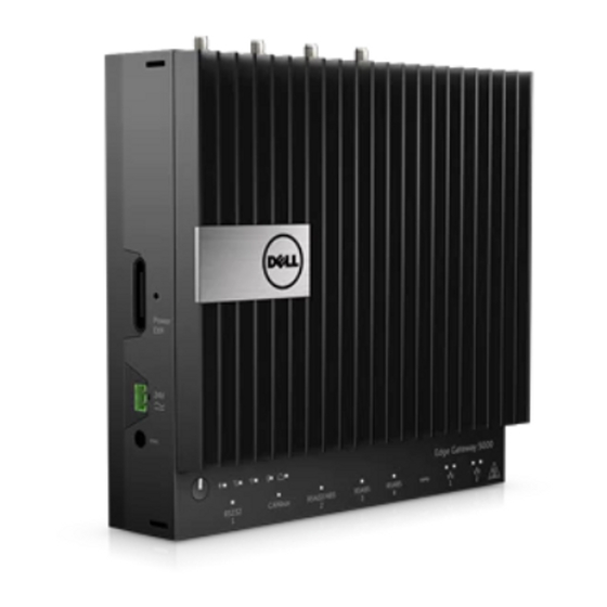
Page 6: System Features
System Features Feature USB 2.0 port For USB 2.0 devices USB 2.0 port For USB 2.0 devices HDMI port Connect a Monitor or another HDMI‑in enabled device. Provides video and audio output. Wi-Fi antenna port (port four) Connect an antenna to increase the range and strength of the Wi-Fi signals. - Page 7 Feature Micro-SIM card slot Insert a micro-SIM card to connect to a mobile broadband network. Mobile broadband antenna Connect an antenna to increase the port (port one) range and strength of the mobile broadband signals. 10. Power module expansion port Connect an external power module for increased power options.
-
Page 8: System Leds
System LEDs Feature Serial port status LED Provide the status of the serial port connection. CANbus port status LED Provide the status of the CANbus port connection. RS422/485 port status LED Provide the status of the RS422/485 port connections. RS485 port status LED Provide the status of the RS485 port connections. -
Page 9: Dip Switches
DIP switches Feature RS422/RS485 port toggle Toggle between RS422 or RS485 switch standard RS422/RS485 port resistor Enable/disable the differential switch termination resistor RS422/RS485 port bias Enable/disable the bias resistor for the resistor switch RS422/RS485 port RS422/RS485 port diagnostic Enable or disable the RS422/RS485 switch port RS485 port resistor switch... -
Page 10: Setting Up Your Dell Edge Gateway
WARNING: Always make sure that the available power source matches the required input power of the Dell Edge Gateway, check the input power markings next to power connector(s) before making connections. The 24 V power source must be compliant with local Electrical Codes and Regulations. -
Page 11: Professional Installation Instructions
WARNING: When installing the Power Module, use a cable appropriate for the load currents: 3-core cable rated 15 A at 90 °C (194 °F) minimum, which conform to either IEC60227 or IEC 60245. The Gateway accepts cables of 14 AWG minimum. WARNING: Before installing that all of three power inputs (Terminal Block/Power Jack/Battery Input) in power module shall be protected by the 20 A fuses or circuit-breakers(over current protection device) in... -
Page 12: Instructions D'installation Professionnelles
Instructions d'installation professionnelles Le personnel d'installation Ce produit est conçu pour des applications spécifiques et doit être installé par un personnel qualifié avec RF et connaissances connexes réglementaire. L'utilisateur ne doit pas tenter générale d'installer ou de modifier le réglage. Lieu d'installation Le produit doit être installé... -
Page 13: Industry Canada Statement
and on, the user is encouraged to try to correct the interference by one of the following measures: • Reorient or relocate the receiving antenna. • Increase the separation between the equipment and receiver. • Connect the equipment into an outlet on a circuit different from that to which the receiver is connected. - Page 14 Cet appareil numérique de la classe B est conforme à la norme NMB-003 du Canada. This device complies with RSS-310 of Industry Canada. Operation is subject to the condition that this device does not cause harmful interference. Cet appareil est conforme à la norme RSS-310 d'Industrie Canada. L'opération est soumise à...
-
Page 15: Powering On The Dell Edge Gateway
5250-5350 MHz et 5650-5850 MHz et que ces radars pourraient causer du brouillage et/ou des dommages aux dispositifs LAN-EL. Powering on the Dell Edge Gateway Install the Gateway on the wall mount using the Dell approved wall mounting kit. -
Page 16: Mounting The Dell Edge Gateway On The Wall
RS422/R485 ports. Mounting the Dell Edge Gateway on the wall You can mount the Dell Edge Gateway on a wall by using mounting brackets. The brackets secure the Dell Edge Gateway to the wall. Secure the two mounting brackets to the rear of the Dell Edge Gateway... - Page 17 Drill four holes in the wall that correspond to the holes in the mounting bracket, then place the Dell Edge Gateway against the wall and align the holes in the mounting brackets with the holes in the wall.
- Page 18 Tighten the screws to secure the Dell Edge Gateway to the wall.
-
Page 19: Mounting The Dell Edge Gateway On A Din Rail
Dell Edge Gateway. Align the screw holes on the DIN rail mount to the back of the Dell Edge Gateway, place the screws on the DIN rail mount and secure it to the Dell... - Page 20 Pull down on the tab to release the latch on the DIN rail mount. Mount the Dell Edge Gateway on a DIN rail.
-
Page 21: Inserting A Micro-Sim Card And Activating Your Mobile Broadband
Secure the Dell Edge Gateway by pressing the latch. Inserting a micro-SIM card and activating your mobile broadband CAUTION: It is recommended to insert the micro-SIM card before powering on the Dell Edge Gateway. Shutdown your system. Locate the micro-SIM card slot. - Page 22 Close the micro-SIM card tray. Power on your Gateway.
-
Page 23: Removing The Micro-Sim Card
Connect to a Network NOTE: To activate your mobile broadband service, please contact the service provider with the following information: Windows OS Select the Network icon from the taskbar and then select Cellular. The Cellular page displays. Select your Mobile Broadband Carrier to expand the options. Select Advanced Options. -
Page 24: Setting Up Your Operating System
NOTE: For more information on setting up your Wind River operating system, see http://www.windriver.com/support. Power on the Gateway. The Wind River splash screen is displayed after the Dell Edge Gateway boots completes POST. The operating system will take around twenty seconds to complete the loading process. -
Page 25: Specifications - Gateway
• 64 GB SSD Dimensions Height 228.4 mm (8.99 inches) Width 216 mm (8.50 inches) Depth • Dell Edge Gateway 5000: 64.20 mm (2.52 inches) • Dell Edge Gateway 5100: 74.50 mm (2.93 inches) Memory Type LPDDR3 Speed 1600 MHz... - Page 26 Power adapter input voltage/current 19.5 VDC / 3.33A Environmental requirements Ingress Protection Rating IP50 Temperature range: Dell Edge Gateway 5000 Operating (with a maximum temperature gradation of 15°C • 0°C to 50°C (32°F to 122°F) when (59°F) per hour) connected to a 24V AC/DC power source.
- Page 27 Environmental requirements • 0°C to 40°C (32°F to 104°F) when connected to a power adapter. NOTE: The maximum operating temperature is derated 1°C/ 305m (1000ft) above sea level altitude Non-operating (with a -40°C to 70°C (-40°F to 158 °F) maximum temperature gradation of 15°C (59°F) per hour) Relative humidity (maximum):...
-
Page 28: I/O Module Overview
The I/O module allows you to install a PCIe x1 card and adds additional ports to your Dell Edge Gateway. NOTE: The power module is required to be installed with the Dell Edge Gateway to enable and use the I/O expansion module. -
Page 29: Features
Features... -
Page 30: Setting Up The I/O Module
Push both the top and bottom release- latch to disconnect the power module from the Dell Edge Gateway. I/O module expansion Connect the I/O module to the Dell connector and guide pin Edge Gateway. Power status light Indicates the power state of the I/O module and the Dell Edge Gateway. - Page 31 Remove the dust cap and loosen the access cover screw that secures the I/O Expansion Module to the cover, slide in the direction shown and carefully lift it off the module. Install the PCIe card on the PCIe expansion card slot on the I/O Expansion Module.
- Page 32 Replace the cover on the I/O Expansion Module. NOTE: Replace the dust-caps on any unused ports and connectors. Tighten the screw that secures the cover to the I/O Expansion Module. Remove the dust-cap covering the I/O Module expansion port on the Dell Gateway connector.
- Page 33 Align the I/O Module guide pin to port on the Dell Edge Gateway. Slide the I/O Module until it is fully seated into the Dell Edge Gateway.
- Page 34 10 Lock the top and bottom latches to secure the module to the Dell Edge Gateway. 11 Install the Dell Edge Gateway and the I/O Module along with the Power Module at a desired location using wall-mount bracket or the DIN rail mount.
-
Page 35: Specifications - I/O Module
Power Module. NOTE: The power adapter and sealed lead-acid battery is sold separately. NOTE: The power module is required to be installed with the Dell Edge Gateway to enable and use the I/O expansion module. Specifications - I/O Module... - Page 36 Power requirements Phoenix connector input voltage/ 24 VAC (50 Hz–60 Hz) or 24 VDC / current Power adapter input voltage/current 19.5 VDC / 6.67A Battery connector port 12 VDC / 15A Environmental requirements Ingress Protection Rating IP50 NOTE: Enclosure meets IP50 with the pre-installed PCIe blank bracket.
- Page 37 Environmental requirements Relative humidity (maximum): Operating (with maximum 10% to 90% (non-condensing) humidity gradation of 10% per hour) Non-operating ((with maximum 5% to 95% (non-condensing) humidity gradation of 10% per hour) Altitude (maximum, unpressurized): Operating -15.2m to 5000m (-50ft to 16,404ft) NOTE: The maximum operating temperature is derated 1°C/ 305m (1000ft) above sea level...
- Page 38 System ambient Maximum Maximum Maximum after altitude supported power supported power supported power derating (°C) dissipation (W) dissipation (W) dissipation (W) for 85° C or for 70° C still air for 55°C still air above still air rated PCIe cards rated PCIe cards rated PCIe cards Not supported...
-
Page 39: Power Module Overview
Power Module Overview The power module allows you to connect additional power sources to your Dell Edge Gateway. The power module allows you to connect to all three power sources, that is, the 24V AC/DC, 19.5 VDC, and a battery. -
Page 40: Features
Features Feature Top release-latch Push both the top and bottom release- latch to disconnect the power module from the Dell Edge Gateway. Power status LED Indicates the power‑state of the power module and the Dell Edge Gateway. -
Page 41: Setting Up The Power Module
Connect the power module to the Dell port Edge Gateway for increased power options and to power the I/O expansion module. Setting up the Power Module WARNING: Before installng the Power Module shutdown the Dell Edge Gateway and disconnect the power cable. - Page 42 NOTE: The power module is required to be connected with the Dell Edge Gateway to enable and use the I/O expansion module. Remove the dust-cap covering the Power Module expansion port on the Dell Gateway connector.
- Page 43 Align the Power Module guide pins to the power module port on the Dell Edge Gateway and slide the Power Module until it is fully seated in the Dell Edge Gateway...
- Page 44 Ensure the top and bottom latches are locked to secure the module to the Dell Edge Gateway...
- Page 45 Install the Dell Edge Gateway and the Power Module at a desired location using wall-mount bracket or the DIN rail mount. Wall-mount bracket DIN rail...
-
Page 46: Power Module - Connecting A Battery
Connect the power sources and press the power button on the Dell Edge Gateway. NOTE: You can connect the power cable to the 24V AC/DC, 19 VDC, and a battery simultaneously. NOTE: The power adapter and sealed lead-acid battery are sold separately. - Page 47 WARNING: Make sure the battery is installed in a secure location and follows all local fire codes and regulation. Read the safety instructions that is shipped with the battery. WARNING: Only a trained technician should setup/replace the battery. WARNING: Only install the battery inside an enclosure that meets fire safety requirements.
-
Page 48: Specifications - Power Module
• Calculate the total length of wire from the battery to the system. • Determine current-carrying capacity in the wire. • Determine correct wire gauge in the intersection of amps and feet. Specifications - Power Module Dimensions Height 117.80 mm (4.64 inches) Width 216 mm (8.50 inches) Depth... - Page 49 Power requirements Terminal block connector input 24 VAC (50 Hz–60 Hz) or 24 VDC / voltage/current Power adapter input voltage/current 19.5 VDC / 6.67A Battery connector port 12VDC / 15A Environmental requirements Ingress Protection Rating IP50 Temperature range: Operating (with a maximum •...
- Page 50 Environmental requirements Storage -15.20 m to 10,668 m (-50 ft to 35,000 ft)
-
Page 51: Enclosure Overview
Enclosure Overview The rugged enclosure allows you to install the Dell Edge Gateway in harsh environment’s, like locations that are subjected to high temperature variation, dust particle, and humidity. Features Feature Rugged Enclosure install the Dell Edge Gateway in the rugged enclosure when using in harsh environments condition. - Page 52 Feature door securing latch (3) secure the enclosure thermal ribs dissipates the heat generated by the system latch lock-out secure the system with a pad lock cable tie-off (17) to prevent accidental cable disconnection, tie all cables to the cable tie-off guides. cable conduit openings (8) route the cables through the conduits (1 inch and .75 inch diameter)
-
Page 53: Setting Up The Enclosure
Setting up the Enclosure Install the Enclosure’s wall mount bracket at a desired location and secure it to the wall using the wall mount screws. NOTE: Ensure the notch on the bracket is on the top. - Page 54 Open the Enclosure. Place the Enclosure on the wall mount bracket and align the tab on the Enclosure to fit into the notch on the wall bracket.
- Page 55 Place and tighten the screws with rubber washers to secure the Enclosure to the wall brackets. Align the screw holes on the wall mount brackets with the screw holes on the Dell Edge Gateway, place and tighten the screws to secure the wall mount brackets to the Gateway.
- Page 56 Align the screw holes on the Dell Edge Gateway’s wall mount brackets with the screw holes on the Enclosure by positioning the Gateway onto the Enclosure’s two locator pins, place and tighten the screws to secure the Gateway to the enclosure...
- Page 57 Connect the intrusion switch to the Gateway.
- Page 58 Remove the desired conduits opening plugs on the bottom or the left side of the enclosure and install the wiring conduits. NOTE: To ensure that dust and water does not enter the enclosure install a conduit rated as IP65.
- Page 59 Route your cables through the cable conduits on the bottom or the left side of the enclosure. NOTE: To reduce the risk of accidental cable disconnection, tie all cables to the cable tie-off guides.
-
Page 60: Specifications - Enclosure
10 Close and securely latch the Enclosure door. Specifications - Enclosure Dimensions Height 397 mm (15.62 inches) Width 443.40 mm (17.46 inches) Depth 79.80 mm (3.14 inches) NOTE: The dimensions do not include the latches and wall bracket on back of enclosure; the wall bracket adds 5 mm to the depth. Environmental requirements IP65 Ingress Protection Rating... - Page 61 Environmental requirements Operating (with a maximum • Dell Edge Gateway 5000: 0°C to temperature gradation of 15°C 45°C (32°F to 113°F) (59°F) per hour) • Dell Edge Gateway 5100: -30°C to 70°C (-22°F to 158°F) NOTE: The maximum operating temperature is derated 1°C/ 305m (1000ft) above sea level altitude.
-
Page 62: Setting Up The Zigbee Dongle
NOTE: Do not connect the ZigBee dongle to the internal USB port of the I/O expansion module. Shut down your Dell Edge Gateway. Connect the ZigBee dongle to any external USB port on your Dell Edge Gateway. Connect the ZigBee dongle to any external USB port on the I/O module. - Page 63 Turn on the Dell Edge Gateway and complete setup. NOTE: For ZigBee development information go to SiLabs developer website at www.silabs.com/ or contact the system’s application provider.
-
Page 64: Contacting Dell
Select the appropriate service or support link based on your requirement or choose the method of contacting Dell that is convenient for you. Dell provides several online and telephone-based support and service options. Availability varies by country and product, and some services may not be available in your area.
Need help?
Do you have a question about the Edge Gateway 5000 Series and is the answer not in the manual?
Questions and answers