
Related Manuals for Dell N01G


Summary of Contents for Dell N01G
- Page 1 Dell Edge Gateway 5000 Series Installation and Operation Manual Computer Model: Dell Edge Gateway 5000/5100 Regulatory Model: N01G/N02G Regulatory Type: N01G001/N02G001...
- Page 2 WARNING: A WARNING indicates a potential for property damage, personal injury, or death. © 2016-2019 Dell Inc. or its subsidiaries. All rights reserved. Dell, EMC, and other trademarks are trademarks of Dell Inc. or its subsidiaries. Other trademarks may be trademarks of their respective owners.
-
Page 3: Table Of Contents
..............................13 24 V AC/DC power port ............................. 14 19.5 V DC power adapter port ................................. 15 System—Right 3 Setting up your Dell Edge Gateway................16 ..........................16 Professional installation instructions ......................... 17 Instructions d'installation professionnelles ................... 17 Federal Communication Commission Interference Statement .............................. - Page 4 ..........................36 Ubuntu Core OS basic functions ..............................37 UEFI capsule update .................................38 Watchdog Timer ..................................38 Security ..........................39 Accessing Snappy Store/Snapweb ..............................40 Cloud LED On/Off ................................. 40 Serial Port ..................................41 Minicom ..............................42 Expansion IO Module ..................................42 Zigbee .............................42 Controller Area Network .........................
- Page 5 General ..............................103 System configuration ..................................103 Security ..................................104 Secure Boot ...................................104 Performance ............................... 104 Power Management ................................105 POST Behavior ...................................105 Maintenance 11 Other documents you may need................. 106 12 Contacting Dell......................107 ........................107 Regulatory and environmental compliance...
-
Page 6: Overview
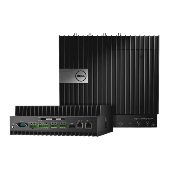
The Dell Edge Gateway 5000/5100 series allows you to connect to network enabled devices wired or wirelessly, and manage them remotely in your existing network ecosystem. The system can also be mounted on the wall using the Dell approved wall mount kit or mounted into your existing rack infrastructure using the DIN-rail mounting bracket. -
Page 7: System Views
System views System—Front Features Power button Press and hold for 2 seconds to turn on the system if it is turned off. NOTE: For more details about the LED indicators on the front of the system, see indicators. -
Page 8: System-Front (Led Indicators)
System—Front (LED indicators) Features Power status LED Indicates the power‑state of the system. Mobile broadband status LED Indicates the mobile broadband status and network activity. Wireless status LED Indicates the wireless connectivity status and network activity. Bluetooth status LED Indicates the Bluetooth status and activity. Cloud connection status LED Indicates the cloud connection status. -
Page 9: Serial Port (Rs232) Connector Mapping
Features RS485 port Connect a RS485 device. RS485 port Connect a RS485 device. USB 3.0 port Connect a USB 3.0 device. Network port Connect an Ethernet (RJ45) cable from a router or a broadband modem for network or internet access. Network port Connect an Ethernet (RJ45) cable from a router or a broadband modem for network or internet access. -
Page 10: Rs485 Connector Mapping
RS485 connector mapping Signal A(-) B(+) Manufacturer part number Molex 359530-5503 https://www.molex.com/ NOTE: This part number is for reference only and is subjected to change. RS422/485 connector mapping Signal TXA(-) / A(-) TXB(+) / B(+) RXA(-) RXB(+) Manufacturer part number Molex 359530-5505 https://www.molex.com/ NOTE: This part number is for reference only and is... -
Page 11: System-Top
Feature RS485 port resistor switch Enable/disable the differential termination resistor for RS485. RS485 port bias resistor switch Enable/disable the bias resistor for the RS485 port. RS485 port resistor switch Enable/disable the differential termination resistor for RS485. RS485 port bias resistor switch Enable/disable the bias resistor for the RS485 port. -
Page 12: Hdmi Connector Mapping
Signal Intrusion detection Cable detection Manufacturer part number Molex 39530-5503 https://www.molex.com/ NOTE: This part number is for reference only and is subjected to change. HDMI connector mapping Signal TMDS Data2+ TMDS Data2 Shield TMDS Data2− TMDS Data1+ TMDS Data1 Shield TMDS Data1−... -
Page 13: System-Left
System—Left Features Power module expansion port Connect an external power module for increased power options. 24 V AC/DC power Phoenix connector Connect an 24 V AC/DC power connector to provide power to your system. 19.5 V DC power adapter port Connect a 19.5 V DC power adapter connector to provide power to your system. -
Page 14: 19.5 V Dc Power Adapter Port
Manufacturer part number Molex 39530-0502 https://www.molex.com/ NOTE: This part number is for reference only and is subjected to change. 19.5 V DC power adapter port Polarity DC Negative DC Positive Manufacturer part number SINGATRON 2DC-S060-029F http://www.singatron.com/ NOTE: This part number is for reference only and is subjected to change. -
Page 15: System-Right
System—Right Features IO expansion port Connect an external expansion module for additional IO ports. -
Page 16: Setting Up Your Dell Edge Gateway
Electrical Codes and Regulations. WARNING: To ensure the protection provided by Dell Edge Gateway is not impaired, do not use or install the system in any manner other than that which is specified in this manual. -
Page 17: Instructions D'installation Professionnelles
External antenna Use only the antenna(s) which have been approved by the applicant. Non-approved antenna(s) may produce unwanted spurious or excessive RF transmitting power which may lead to a violation of FCC/IC limits and is prohibited. Installation procedure Please refer to user’s manual for the detail. WARNING: Please carefully select the installation position and make sure that the final output power does not exceed the limits set forth in relevant rules. -
Page 18: Industry Canada Statement
• This transmitter must not be co-located or operating in conjunction with any other antenna or transmitter. Radiation Exposure Statement: This equipment complies with FCC radiation exposure limits set forth for an uncontrolled environment. This equipment should be installed and operated with minimum distance 20cm between the radiator & your body. NOTE: The country code selection is for non-US model only and is not available to all US model. -
Page 19: Setting Up The Edge Gateway
The maximum antenna gain permitted for devices in the band 5725-5825 MHz shall comply with the eirp limits specified for point-to-point and non point-to-point operation as appropriate. The worst-case tilt angle(s) necessary to remain compliant with the eirp elevation mask requirement set forth in Section 6.2.2(3) shall be clearly indicated. - Page 20 Install the WWAN antenna to enable the wireless connections—optional. Connect a display to the Edge Gateway (if necessary). Connect a keyboard and mouse if accessing the Edge Gateway directly.
- Page 21 Connect a grounding cable to the Edge Gateway (if necessary). Connect a SELV/limited energy circuit power source to the Edge Gateway and press the power button to turn it on. NOTE: For marine applications, connect an EMI filter such as OnFILTER CleanSweep APN515FG or equivalent between the power source and the Edge Gateway, and then press the power button to turn it on.
-
Page 22: Mounting The Edge Gateway On The Wall
If setting up the Edge Gateway for the first time, complete the operating system setup. NOTE: The Edge Gateway is shipped with Windows 10 Enterprise, Ubuntu Snappy, or Wind River Linux operating systems. Do this later when prompted to enter the product key. NOTE: On Windows 10 OS, select NOTE: The default username and password for Ubuntu-Snappy-Core is •... - Page 23 Drill four holes in the wall that correspond to the holes in the mounting bracket, then place the Edge Gateway against the wall and align the holes in the mounting brackets with the holes in the wall. Tighten the screws to secure the Edge Gateway to the wall.
-
Page 24: Mounting The Edge Gateway On A Din Rail
Mounting the Edge Gateway on a DIN rail The Edge Gateway can be mounted on a DIN rail. The DIN rail bracket mounts to the back of the Edge Gateway. NOTE: In some environments where the Edge Gateway is installed, a more robust mounting method is required. For example, in marine applications, due to vibrations unique to that environment, only a wall mount should be used. - Page 25 Mount the Edge Gateway on a DIN rail. Secure the Edge Gateway to the DIN rail by pressing the latch.
-
Page 26: Inserting A Micro-Sim Card And Activating Your Mobile Broadband
Inserting a micro-SIM card and activating your mobile broadband CAUTION: Dell recommends that you insert the micro-SIM card before powering on the Edge Gateway. Shut down your Edge Gateway. Locate the micro-SIM card slot. Use a paper clip or SIM eject tool to eject the micro-SIM card tray. - Page 27 Click the play button to connect to your HSPA+ network. NOTE: Click the information button to view the International Mobile Equipment Identity (IMEI) and Integrated Circuit Card Identifier (ICCID) information. Click the stop to disconnect from your HSPA+ network. If the Edge Gateway is shipped with LTE Verizon (DW5812) WWAN or LTE AT&T (DW5813) card: Select the network icon from the taskbar and then click Cellular.
- Page 28 Example: at+cgdcont=3,"IPV4V6","vzwinternet". NOTE: If the command runs successfully, the message OK appears. Configure the Network Control Mode with the at#ncm command. Example: at#ncm=1,3. Activate the Packet Data Protocol with the at+cgact command. Example: at+cgact=1,3. To view the PDP Context Read Dynamic Parameters, that is, bearer_id, apn, ip_addr, subnet_mask, gw_addr, DNS_prim_addr, DNS_sec_addr, P-CSCF_prim_addr, and P-CSCF_sec_addr parameters, run the at+cgcontrdp command.
- Page 29 Example: at+cgdcont=3,"IPV4V6","broadband". NOTE: If the command runs successfully, the message OK appears. Configure the Network Control Mode with the at#ncm command. Example: at#ncm=1,3. Activate the Packet Data Protocol with the at+cgact command. Example: at+cgact=1,3. To view the PDP Context Read Dynamic Parameters, that is, bearer_id, apn, ip_addr, subnet_mask, gw_addr, DNS_prim_addr, DNS_sec_addr, P-CSCF_prim_addr, and P-CSCF_sec_addr parameters, run the at+cgcontrdp command.
-
Page 30: Setting Up Your Operating System
Select Fully clean the drive → Reset. Windows 10 IoT Enterprise LTSB basic functions BIOS update BIOS updates for the Edge Gateway may be downloaded from www.dell.com/support. The download includes an executable that can run from a local machine. Watchdog Timer The Watchdog Timer for Windows 10 IoT Enterprise LTSB is controlled from the BIOS setting. - Page 31 Cloud LED NOTE: To utilize the Cloud LED, download the necessary tools and drivers from www.dell.com/support. One unique feature of the Edge Gateway 5000 Series is the Cloud LED. Cloud LED enables you to visually inspect the operational status of the Edge Gateway by looking at the display light on the left panel of the Edge Gateway.
-
Page 32: Common Port Mappings
Common port mappings Serial port mapping Table 1. Serial port mapping Number Port type Connector Device node RS232 COM1 RS422/485 5-pin terminal COM2 RS485 3-pin terminal COM3 RS485 3-pin terminal COM4 Edge Gateway I/O module GPIO mapping The GPIOs on the external I/O Module for the Edge Gateway are behind the PIC microcontroller. The PIC microcontroller is exposed to the host system and to the host OS as a USB-HID device. -
Page 33: Boot Up And Log In
• .NET Framework 4.5.2 or higher • A Windows computer with administrator rights and at least 8 GB of available storage space to download the Dell ISO recovery image • A blank USB flash drive with at least 8 GB of storage space. - Page 34 Insert the recovery USB flash drive into the USB port on the Edge Gateway. Power on the Edge Gateway. When the Dell logo appears on the screen, press F12 to enter the one-time boot screen, and the select USB storage. On the next screen, select OS Recovery.
-
Page 35: Updating Operating System And Applications
Power on the Edge Gateway. When the Dell logo appears on the screen, press F12 to enter the one-time boot screen, and the select USB storage. The Edge Gateway boots through the USB flash drive and flashes the Ubuntu Core 16 installation image into storage automatically. -
Page 36: Ubuntu Core Os Basic Functions
Returns Name Date Version Developer ubuntu-core 2015-10-13 ubuntu bluez 2015-10-20 5.34-2 canonical* network-namager 2015-10-20 canonical* plano-uefi-fw-tools 2015-10-20 canonical* webdm 2015-10-20 0.9.2 canonical* plano-webdm 2015-10-20 canonical* NOTE: Check if a newer version of the software is available. For more information on checking for updates, see Updating operating system and applications. -
Page 37: Uefi Capsule Update
Run the command: admin@localhost:$ cat /sys/ class/dmi/id/board_vendor returns Dell Inc. The system tag is printed. UEFI capsule update The fwupgmgr tool or commands are used to update the UEFI BIOS on the system. The UEFI BIOS for this platform is released... -
Page 38: Watchdog Timer
Connect and login to the Edge Gateway. Check the current BIOS details. $sudo uefi-fw-tools.fwupdmgr get-devices Check if the update is available from LVFS service. $sudo uefi-fw-tools.fwupdmgr refresh Download the BIOS from the www.dell.com/support. $sudo uefi-fw-tools.fwupdmgr get-updates Apply the update. $sudo uefi-fw-tools.fwupdmgr update -v Restart the system. -
Page 39: Accessing Snappy Store/Snapweb
TPM is only supported on devices that have TPM hardware installed on products with Snappy-enhanced security support. The TPM on/off setting is configurable in the BIOS and manageable in the operating system. If TPM is turned off, the device node (/dev/tpm0) does not exist. (plano)ubuntu@localhost:~$ ls /dev/tpm0 ls: cannot access /dev/tpm0: No such file or directory If TPM is turned on, the device node (/dev/tpm0) exists. -
Page 40: Cloud Led On/Off
You can now access the snapweb. Cloud LED On/Off Cloud LED enables you to visually inspect the operational status of the Edge Gateway by looking at the display light on the left panel of the Edge Gateway. To export Cloud LED PIN, run the command: #sudo su –... -
Page 41: Minicom
Table 3. Serial device nodes mapping table. Port Type Connector Device Node RS232 /dev/ttyS6 RS422_485 5 pin terminal /dev/ttyS4 RS485 3 pin terminal /dev/ttyS5 RS485 3 pin terminal /dev/ttyS2 Execute the #sudo chmod 777 /dev/ttyS# command on two systems, where # is port number corresponding to ports being used. -
Page 42: Expansion Io Module
Zigbee The Edge Gateway supports a USB Zigbee dongle (purchased from Dell) as an optional add-on hardware. When the Zigbee dongle is present on the system, it is enumerated to the OS as a USB device. There is no native application software to perform Zigbee protocol for this device. -
Page 43: Network Manager - Ubuntu Core 15
• for i in /sys/class/hidraw/*; do udevadm info $i --attribute-walk | grep -q 'CANBus HID Device' && echo path: /dev/$(basename $i); done Network Manager – Ubuntu Core 15 Network-Manager is a native Ubuntu Snappy Connection Manger, the application handles multiple network devices, provides detection and configuration for system to automatically connect to network. -
Page 44: Network Manager - Ubuntu Core 16
Run the $trust <MAC address of bluetooth keyboard> command to turst the Bluetooth keyboard. Run the $connect <MAC address of bluetooth keyboard> command to connect the to the Bluetooth keyboard. Run the $quit command to quit the bluetoothctl console. Network Manager – Ubuntu Core 16 Network-Manager is a native Ubuntu Snappy Connection Manager, the application handles multiple network devices, provides detection and configuration for the system to automatically connect to the network. -
Page 45: Flashing The Bios
• Connect: $ sudo network-manager.nmcli dev wifi connect $SSID password $PSK ifname $WIFI_INTERFACE • Disconnect: $ sudo network-manager.nmcli dev disconnect $WIFI_INTERFACE Connecting through Software-enabled Access Point (SoftAP) This feature depends on the wireless module and its associated driver to function as a wireless access point. NOTE: For more information on SoftAP, see https://docs.ubuntu.com/core/en/stacks/network/wifi-ap/docs/index. -
Page 46: Wind River Linux
Insert the USB flash drive in one of the available USB ports on the Edge Gateway. Power on the Edge Gateway. When the Dell logo is displayed on the screen, press F12 to enter the one-time boot screen. On the one-time boot screen, select Flash the BIOS . -
Page 47: Restoring Wind River Linux
The Wind River Linux operating system is damaged. Connect a keyboard, mouse, and monitor to the Edge Gateway, or connect to the Edge Gateway through a KVM session, Dell Wyse Cloud Client Manager (CCM), or Dell Command | Monitor (DCM). -
Page 48: Wind River Linux Basic Functions
Wind River Linux Basic Functions Preinstalled Packages Run the root@WR-IDP-xxxx:~# rpm -qa command to list all the packages installed on the Wind River Linux OS. NOTE: If you are looking for a specific package, you have to pipe the output of the root@WR-IDP-xxxx:~# rpm -qa command to search for that specific package. - Page 49 TPM support (HW TPM module dependency) Run the root@WR-IDP-xxxx:~# tpm_statistic command displays the status of TPM service. If the TPM is functional and enabled in the BIOS, below would be the expected results, when tpm_statistic command is executed. Expected result: The expected result is for TPM Chip Presence: Normal. Example of the response to the above command should be similar to the output shown below.
- Page 50 • • wlan0 Network configuration and default setup The following commands can be used to configure different network interfaces on the system with Wind River Linux on it. Network configuration on Wind River Linux IDP 3.1 environment can be performed through the LuCi web interface. NOTE: The LuCi web interface supported in the default OS image.
- Page 51 through the system. The issued IP addresses by the access point and eth1 interface are in the 192.168.1.x subnet. The default access point SSID for the access point is IDPDK-5591. The bridge configuration can be modified using LuCi web interface. Follow Intel/Wind River’s documentation for more details on configuring, WAN, WLAN, and br-LAN network interfaces using LuCi web interface.
- Page 52 Launch minicom terminal utility on the system with one of the USB ACM device port to identify that we have the correct USB ACM device for Telit LE910 device before configuring the device, e.g. below shows how to launch minicom with ttyACM1 as interface: •...
- Page 53 Description: The following are a capture from a sample session that was performed on a Edge Gateway platform with default Wind River Linux OS image to establish LTE connectivity using Verizon LE910 module and Verizon SIM card. The commands highlighted were typed and the other is response from the system.
- Page 54 Description: The following method can be used to disable or delete the WWAN connection that was setup using the descriptions mentioned in the previous sections. Launch minicom as defined in the other sections and choose the appropriate ttyACM port for the Telit module Inside the minicom terminal send the following AT commands At+gmi (to make sure it is the Telit module)
- Page 55 Add apn according to the SIM card operator. For e.g. "3gnet" for China Unicom root@WR-IDP-XXXX:~# uci set network.wwan.apn="3gnet" root@WR-IDP-XXXX:~# uci commit network root@WR-IDP-XXXX:~# uci get network.wwan.apn3gnet Setup WWAN interface. restart wwan interface: root@WR-IDP-XXXX:~# ifdown wwan ; ifup wwan restart all interfaces: root@WR-IDP-XXXX:~# systemctl restart netifd Step 2 and Step 3 can also be performed through in LuCi web interface.
- Page 56 Some of the detailed documentation on how to develop for Wind River Linux OS image based Edge Gateway 5000 solution and how to utilize built in Developer Hub are available at www.intel.com/gatewaytraining please refer to that site for more details. The following steps gives basic guidelines to follow once you receive your Edge Gateway 5000 product with Wind River Linux IDP 3.1 base OS image.
- Page 57 • Select the packages tab inside the IoT Developer Hub, search for iot-developer-hub package and select to update that package only, it is not necessary to update other packages at this time. Give few minutes for package to download and update. •...
- Page 58 • Once the update of the OS is complete, the Edge Gateway should reboot and now the system should be upgraded to the latest RCPL release available for the Edge Gateway 5000 product at the Windshare repository. At this point the user should have an environment ready to develop other layers of applications on top of the Edge Gateway 5000 system.
- Page 59 Serial Port Mapping Description: The following table show the serial port mapping on the Edge Gateway 5000 platform installed with Dell factory installed Wind River Linux OS image. For dip switch setting on the Edge Gateway for RS422 and RS485 ports please refer to appropriate hardware installation guide document.
- Page 60 The I/O module GPIO mapping and references will be provided as a separate technical sheet and article and will be released at the support web portal for user/customer reference. Edge Gateway I/O Module PCIe expansion mapping Description: The PCIe slot on the external I/O module for the Edge Gateway are driven directly from the host PCIe bus. Since it is generic PCIe expansion there are no PCIe device specific drivers integrated into the Wind River Linux OS image.
- Page 61 Edge Gateway CAN Module Functions Description: The Edge Gateway supports an optional CAN module that is mounted inside the Edge Gateway itself. The CAN module is enumerated to the OS as a USB device as USB HID device to the Linux kernel driver layer on the Wind River Linux host. There are no native application software on the factory installed OS image to perform CAN protocol for this device.
-
Page 62: System Specifications
5100 Standard FR4 Isola 370HR Intel E3825/E3827 Intel E3825/E3827 Memory Dell-managed Dell-managed BIOS Flash Dell-managed 128 MB SPI FLASH Dell-managed 128 MB SPI FLASH Super I/O Fintek F81960D-I Fintek F81960D-I LAN on system-board Realtek RTL81191-CG Realtek RTL81191-CG Nuvoton NPCT6SO series... -
Page 63: Memory
Memory 5000 5100 Type DDR3L DDR3L Memory channel Single/dual Single/dual Minimum memory 2 GB 2 GB Maximum system memory 8 GB 4 GB Drives and removable storage 5000/5100 Supported number of mSATA hard drives (maximum) 32GB M.2 Solid State Drive 64GB M.2 Solid State Drive NOTE: For hard drives, ‘GB’... - Page 64 Mechanical and environmental specifications Mounting Wall mounted Connector type SMA male Antenna color White Cable type Plenum rated low loss RG58 Cable color White Mounting bracket Swivel type (plastic) Mounting bracket length (approximate) 175 mm (6.89 in) Mounting bracket color Black Pig tail length 500 mm ±...
-
Page 65: Communications-Wwan Antenna
Coaxial cable specification Jacket pullout 4.5 pound-force minimum on 76.2 mm (3 in) section at 12.7 mm (0.5 in) per minute Minimum bend radius 12.7 mm (0.5 in) static bend Leakage -90 dB Communications—WWAN antenna General specifications Antenna PCB Dipole type Number of ports... - Page 66 Mechanical and environmental specifications Mounting bracket Swivel type (plastic) Mounting bracket length (approximate) 175 mm (6.89 in) Mounting bracket color Black Pig tail length 1000 mm (39.37 in) Coaxial cable specification Impedance 50 ± 2.0 ohms Structural return loss -16 dB or better from 100-2500 MHZ un-terminated sample (direct bridge method) Nominal RTL reference -16 dB or better to 6.0 GHz...
- Page 67 Measured antenna peak gain (antenna only) Main antenna Auxiliary antenna Frequency (MHz) Horizontal (dBi) Vertical (dBi) Horizontal (dBi) Vertical (dBi) 0.09 0.63 1.19 1.12 -0.11 0.66 0.89 0.91 -0.27 0.60 0.51 0.78 -0.08 0.55 0.42 0.86 0.17 0.57 0.68 0.97 0.35 0.60 0.86...
- Page 68 Measured antenna peak gain (antenna only) 1.71 1.00 2.13 0.94 1.65 1.03 1.87 0.82 1.57 1.16 1.61 0.74 1.30 1.36 1.24 0.60 1.43 1.31 0.98 0.69 1710 2.19 2.18 1.83 2.39 1730 2.25 2.29 1.66 2.36 1750 1.90 2.15 1.39 2.29 1770 1.33...
-
Page 69: Graphics/Video Controller
Measured antenna peak gain (antenna only) 2400 1.29 1.91 1.85 1.63 2500 3.17 2.75 2.94 2.47 2515 3.11 2.62 2.78 2.47 2535 2.88 2.42 2.55 2.48 2555 2.51 2.09 2.18 2.46 2570 2.21 1.91 1.92 2.46 2570 2.21 1.91 1.92 2.46 2595 1.89... -
Page 70: Dimensions And Weight
Number of ports Manufacturer part number RS-422/RS-485 combo (configurable via Molex 39530-5505 DIP switches) https://www.molex.com/ NOTE: This part number is for reference only and is subjected to change. Network connector (RJ-45)–Dual gigabit None ethernet HDMI Port 1.4 None Line out for headphones or speakers None None Universal audio jack... -
Page 71: Packaging Dimensions And Weight
Packaging dimensions and weight 5000 5100 IO Module Power module IP65 rugged enclosure Height 34.4 cm (13.56 in) 34.4 cm (13.56 in) 25.4 cm (10 in) 25.4 cm (10 in) 52.7 cm (20.75 in) Width 29.5 cm (11.63 in) 29.5 cm (11.63 in) 13.2 cm (5.2 in) 11.4 cm (4.49 in) 15.9 cm (6.26 in) -
Page 72: Environmental Conditions-Io Module
Environmental requirements Operating (with maximum humidity gradation of 10% 10% to 90% (non-condensing) per hour) Non-operating ((with maximum humidity gradation of 5% to 95% (non-condensing) 10% per hour) Altitude (maximum, unpressurized): Operating -15.2 m to 5000 m (-50 ft to 16,404 ft) NOTE: The maximum operating temperature is derated 1°C/305 m (1000 ft) above sea level altitude. -
Page 73: Environmental Conditions - Power Module
Supported PCIe card power—PCIe card temperatures and power ratings must meet following requirements: System ambient after altitude Maximum supported power Maximum supported power Maximum supported power derating (°C/°F) dissipation (W) for 85°C dissipation (W) for 70°C dissipation (W) for 55°C (185°F) or above still air rated (158°F) still air rated PCIe (131°F) still air rated PCIe... -
Page 74: Environmental Conditions - Enclosure
Environmental requirements Operating -15.2m to 5000m (-50ft to 16,404ft) NOTE: The maximum operating temperature is derated 1°C/305m (1000ft) above sea level altitude. Storage -15.20 m to 10,668 m (-50 ft to 35,000 ft) Environmental conditions - Enclosure Environmental requirements Ingress protection rating IP65 NOTE: Require IP65 or above conduit connection. -
Page 75: Power
Maximum shock 5000 5100 Operational 40 G, 2 ms 40 G, 2 ms Non-operational 160 g, 2 ms Half Sine Shock 160 g, 2 ms Half Sine Shock Maximum altitude 5000 5100 Operational -15.2 m to 5000 m (-50 ft to 16,404 ft) -15.2 m to 5000 m (-50 ft to 16,404 ft) Non-operational -15.2 m to 10,668 m (-50 ft to 35,000 ft) -
Page 76: 3.0 V Cmos Coin-Cell Battery
Shun Wo & KTS Lithium Edge Gateway 5100 BR2032 Panasonic Lithium NOTE: Dell recommends checking or replacing the coin-cell battery prior to operation if the system has been disconnected from a power source for more than two years. Security 5000/5100 • TPM 1.2 Trusted Platform Module (TPM) •... -
Page 77: Environmental
Available on-site service NOTE: For a copy of our guarantees or limited warranties, write to ‘Dell USA L.P., Attn: Warranties, One Dell Way, Round Rock, TX 78682’. For more information, visit www.dell.com/warranty. NOTE: Service may be provided by third-party. A technician will be dispatched if necessary following phone-based troubleshooting. -
Page 78: O Module Overview
The I/O module allows you to install a PCIe x1 card and adds additional ports to your Dell Edge Gateway. NOTE: The power module is required to be installed with the Dell Edge Gateway to enable and use the I/O expansion module. -
Page 79: Io Module-Top
IO module—Top Features Top release latch Push both the top and bottom release latches to disconnect the power module from the Edge Gateway. USB 2.0 port For USB 2.0 devices. USB 2.0 port For USB 2.0 devices. GPIO port Connect a GPIO 8–pin cable. RS232 port Connect an RS232 cable. -
Page 80: Io Module-Bottom
https://www.molex.com/ NOTE: This part number is for reference only and is subjected to change. RS232 port on IO expansion module connector mapping Signal Signal NOTE: This is a standard serial port connector. IO module—Bottom Features Bottom release latch Push both the top and bottom release latches to disconnect the power module from the Edge Gateway. - Page 81 Align the power module guide pins to the power module port on the Edge Gateway and slide the power module toward the Edge Gateway until fully seated. Ensure the top and bottom latches are locked to secure the module to the Edge Gateway.
- Page 82 Install the Edge Gateway and the IO module along with the power module at a desired location using a wall-mount bracket or the DIN rail mount. Wall mount bracket DIN rail mount Connect to a power source, and press the power button.
-
Page 83: Installing The Pcie Card Into The Io Module
NOTE: Connect a power cable to the 24 V AC/DC or 19.5 V DC power adapter port on the power module. NOTE: The power adapter and sealed lead-acid battery is sold separately. NOTE: To enable and use the IO expansion module, you must also install the power module. Installing the PCIe card into the IO module CAUTION: Electrical and electronic devices are sensitive to electrostatic discharge (ESD). - Page 84 Remove the PCIe expansion card-slot cover. Install the PCIe card into the PCIe expansion card slot on the IO expansion module and secure with a screw. Replace the cover on the IO expansion module.
- Page 85 Tighten the screw that secures the cover to the IO expansion module. NOTE: Replace the dust caps on any unused ports and connectors.
-
Page 86: Power Module Overview
Power Module Overview The power module allows you to connect additional power sources to your Dell Edge Gateway. The power module allows you to connect to all three power sources, that is, the 24V AC/DC, 19.5 VDC, and a battery. -
Page 87: Power Module-Front
Power module—Front Features Power status LED Indicates the power‑state of the power module and the Edge Gateway. Battery status LED Indicates the power‑state of the attached battery. -
Page 88: Power Module-Bottom
Power module—Bottom Features 19.5 V DC power adapter port Connect a 19.5 V DC power adapter to provide power to your Edge Gateway. 24 V AC/DC power port Connect a 24 V AC/DC power source to power your Edge Gateway. Sealed lead-acid battery port Connect an external battery to the power module to provide back-up power in case of power interruption. - Page 89 24 V AC/DC power port Polarity AC/DC-IN Positive/Negative Manufacturer part number Molex 39530-0502 https://www.molex.com/ NOTE: This part number is for reference only and is subjected to change. Sealed lead-acid battery port Polarity Battery status Negative Positive Manufacturer part number Molex 39530-0503 https://www.molex.com/ NOTE: This part number is for reference only and is subjected to change.
-
Page 90: Power Module-Top
Power module—Top Features Top release latch Push both the top and bottom release latches to disconnect the power module from the Edge Gateway. -
Page 91: Power Module-Right
Power module—Right Features Edge Gateway expansion port Connect the power module to the Edge Gateway for increased power options and to power the IO expansion module. Setting up the power module WARNING: Before installing the power module, shut down the Edge Gateway and disconnect the power cable. NOTE: To enable and use the IO expansion module, you must also install the power module. - Page 92 Align the power module guide pins to the power module port on the Edge Gateway and slide the power module until fully seated. Ensure the top and bottom latches are locked to secure the module to the Edge Gateway. Secure the power module to the wall or to the DIN rail.
- Page 93 Wall mount bracket DIN rail Connect the power sources and press the power button on the Edge Gateway.
-
Page 94: Specifications - Power Module
NOTE: You can connect the power cable to the 24V AC/DC, 19 VDC, and a battery simultaneously. NOTE: The power adapter and sealed lead-acid battery are sold separately. NOTE: Installing the battery is optional. Dell recommends that you connect a sealed 12V lead-acid battery to the power module. - Page 95 Environmental requirements NOTE: The maximum operating temperature is derated 1°C/305m(1000ft) above sea level altitude. Non-operating -40°C to 70 °C (-40°F to 158°F) Relative humidity (maximum): Operating (with maximum humidity gradation of 10% 10% to 90% (non-condensing) per hour) Non-operating ((with maximum humidity gradation of 5% to 95% (non-condensing) 10% per hour) Altitude (maximum, unpressurized):...
-
Page 96: Enclosure Overview
Enclosure Overview The rugged enclosure allows you to install the Dell Edge Gateway in harsh environment’s, like locations that are subjected to high temperature variation, dust particle, and humidity. Enclosure (optional) view Enclosure - Side Features Rugged enclosure Install the Edge Gateway in the rugged enclosure when using in harsh environments condition. -
Page 97: Setting Up The Enclosure
Features Cable conduit openings (8) Route the cables through the conduits (1 inch and 0.75 inch diameter). Primary ground (internal) Connect the grounding cable to the system. Primary ground (external) Connect the grounding cable to the system. Door-stop cables (2) Restricts the door from opening. - Page 98 Secure the enclosure to the wall bracket by using the rubber washers and screws. Secure the enclosure mounting brackets to the Edge Gateway by using the screws. NOTE: Before attaching the brackets to the Edge Gateway, note the correct orientation of the brackets. Position the Edge Gateway onto the enclosure’s two locator pins, and then place and tighten the screws to secure the Edge Gateway to the enclosure.
- Page 99 Connect the intrusion switch to the system. Remove the desired conduit plugs on the bottom or the left side of the enclosure and install the wiring conduits. NOTE: To ensure that dust and water does not enter the enclosure, install a conduit rated as IP65.
- Page 100 Route the cables through the conduits and connect the cables to the desired connectors. NOTE: To reduce the risk of accidental cable disconnection, tie all cables to the cable tie-off guides. 10. Close and securely latch the enclosure door.
-
Page 102: Setting Up The Zigbee Dongle
Setting up the Zigbee dongle NOTE: Only Zigbee dongles purchased from Dell work with the Edge Gateway. CAUTION: Do not connect the Zigbee dongle if the Edge Gateway is installed inside the enclosure. NOTE: Do not connect the Zigbee dongle to the internal USB port of the IO expansion module. -
Page 103: Bios Defaults
BIOS defaults General These settings are set at the factory and are not configurable. System configuration 5000 5100 Integrated NIC Enabled w/PXE Enabled w/PXE Integrated NIC 2 Disabled Disabled Serial port Enabled Enabled I/O Module Enabled Enabled SATA Operation AHCI AHCI Drives Enabled (SSD-1) -
Page 104: Secure Boot
5000 5100 Password Bypass Disabled Disabled Password Change Enabled Enabled TPM 1.2 Security Enabled Enabled Disabled (PPI Bypass for Enable Disabled (PPI Bypass for Enable Commands, PPI Bypass for Disable Commands, PPI Bypass for Disable Commands, Clear) Commands, Clear) TPM 2.0 Security Enabled Enabled Disabled (PPI Bypass for Enable... -
Page 105: Post Behavior
NOTE: With USB wake support from power off (S5), a wired keyboard or mouse is able to wake the system if connected to the designated USB port (marked with the Smart Power On icon). For wireless keyboard and mice, if both devices share the same USB dongle and the dongle is inserted into the designated USB port, both keyboard and mouse can wake the system. -
Page 106: Other Documents You May Need
Dell Edge Device Manager Getting Started Guide • Dell SupportAssist For Dell OpenManage Essentials Quick Start Guide • Dell Command | Monitor User's Guide Additionally, for more information on using Dell Data Protection | Encryption see the documentation for the software at https:// www.dell.com/support/manuals. -
Page 107: Contacting Dell
Go to www.dell.com/contactdell. Verify your country or region in the drop-down list at the bottom of the page. Select the appropriate service or support link based on your requirement or choose the method of contacting Dell that is convenient for you.
Need help?
Do you have a question about the N01G and is the answer not in the manual?
Questions and answers