Table of Contents
Advertisement
Advertisement
Table of Contents

Subscribe to Our Youtube Channel
Related Manuals for Projecta HDBM4000


Summary of Contents for Projecta HDBM4000
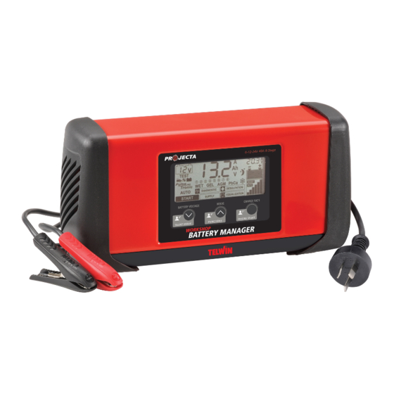
- Page 1 6/12/24V 40A 8 STAGE AUTOMATIC WORKSHOP CHARGER & BATTERY MANAGER P/No. HDBM4000...
-
Page 2: Important Safety Information
IMPORTANT SAFETY INFORMATION Please read this manual thoroughly before use and store in a safe place for future reference. WARNINGS • Explosive gases. Prevent flames and sparks. Provide adequate ventilation during charging. • Before charging, read the instructions. • For indoor use. Do not expose to rain. •... -
Page 3: Table Of Contents
INDEX 1. Features Page 4 1.1 Specifications Page 6 1.2 Product Overview Page 7 1.3 Assembly/Set Up Page 9 2. Operation Page 10 2.1 Setting Battery Voltage Page 11 2.2 Pulse –Tronic Charge Page12 2.2.1 Charge Function Modes Page 12 2.2.2.1 Storing Pulse-Tronic Charge Page 14 2.2.2.2 Storing Supply/Diagnostic Mode... -
Page 4: Features
FEATURES AUTOMATIC 8 STAGE CHARGING Automatic 8 stage charging delivers a complete and thorough charge giving your batteries longer life & better performance. Once the battery is fully charged, the battery charger will continue to monitor the battery without the risk of overcharging. STAGE 1: Checks battery settings with battery STAGE 2: Desulphation stage is designed to break down sulphation occurring in batteries that have been left flat for extended periods of time, returning them back... - Page 5 AUTO/MANUAL ADJUSTABLE OUTPUT Manually or use the Automatic charge setting feature to adjust the rate of charge to best suit different battery sizes. MULTI VOLTAGE OPERATION Suitable for charging 6V, 12V & 24V batteries. SHORT CIRCUIT & POLARITY PROTECTION POWER SUPPLY MODE Supply Power to the vehicle whilst the battery is being changed.
-
Page 6: Specifications
1.1 SPECIFICATIONS P/No. HDBM4000 Type 8 Stage Automatic Input 240V, 50Hz, 600W Output 3-40A 3-40A 3-20A Engine Start – 70A for 3 sec – Minimum Start 2.0V 2.0V 2.0V Voltage Charge Voltages (Absorption) AUTO 7.2V 14.4V 28.8V AUTO i 7.7V 15.4V... -
Page 7: Product Overview
1.2 PRODUCT OVERVIEW Figure A 13 12 Display of the set battery voltage value. Main display. Display: measured battery voltage, current, Ah selection, voltage value selected for the Supply / Diagnostic / Equalization programs, interface messages for the operator, alarm codes. Polarity inversion, short circuit, worn out or faulty battery alarm. - Page 8 11. Choice of the battery production technology: WET: lead-acid batteries with liquid electrolyte; GEL: lead-acid batteries, sealed, with solid electrolyte; AGM: lead-acid batteries, sealed, with electrolyte on absorbent material; PbCa: lead-calcium batteries. 12. SUPPLY mode. 13. DIAGNOSTIC mode. 14. PULSE TRONIC charge process phases. 15.
-
Page 9: Assembly/Set Up
1.3 ASSEMBLING CHARGING LEADS TO BATTERY CLAMPS The HDBM400 battery charger is shipped with the battery clamps disconnected from the positive & negative charging leads. IMPORTANT: • The negative (Black) battery clamp must be connected to the charging lead with the black heat shrink on the lug. - Page 10 INITIAL CONDITION ò DEVICE OFF Keep pressed the button “Battery Voltage” and plug into mains socket. Release button “Battery Voltage” after 7”. BATTERY VOLTAGE 7” 230V - 1ph 50/60 Hz CABLE CALIBRATION DISPLAY 7” BEEP DISPLAY BATTERY VOLTAGE OPERATING INSTRUCTIONS Follow the instructions in the order given below.
-
Page 11: Operation
a. Make sure the level of electrolyte covers the battery plates; if they are not covered, add distilled water until they are submerged by 5–10 mm. ATTENTION! BE VERY CAREFUL WHILE CARRYING OUT THIS OPERATION BECAUSE THE ELECTROLYTE IS AN EXTREMELY CORROSIVE ACID. 2. -
Page 12: Pulse-Tronic Charge
2.2 PULSE-TRONIC CHARGE 2.2.1 CHARGE FUNCTION MODES There are various Pulse Tronic charge procedures that depend on the battery construction technology (T) and the charge current (C). When the battery is charged, the battery charger switches automatically to maintenance mode. BATTERY TYPE SELECTION DISPLAY AUTOMATIC... - Page 13 c) CUSTOMISED PULSE-TRONIC It is possible to select: – the battery construction technology (fig. A.11)choosing between:“WET, GEL, AGM, PbCa” – the charge current (fig.A.6) choosing between:“AUTO” - automatic setting according to battery conditions;“BOOST” - rapid charge; – the Ah - customised setting of the battery Ah (fig.A.2) using 6 predefined values selected using the “CHARGE RATE”...
-
Page 14: Storing Pulse-Tronic Charge
END OF CHARGE – EXAMPLE CHARGE COMBINATION CHART Battery Type (T) Battery Current (C) AUTO Auto Auto Boost Manual ‘Ah’ AUTO i Auto Auto Boost Manual ‘Ah’ WET, GEL, AGM, PdCa Auto Auto Boost Manual ‘Ah’ 2.2.2 CHARGE FUNCTION MODES It is possible to store the last function modes, so they are immediately available after any switching ON/OFF. -
Page 15: Battery And Alternator Test
2.3 BATTERY AND ALTERNATOR TEST The measurements can be performed with the battery connected to the vehicle, after connecting the clamps. Select the measurement to be performed using the “MODE” button (fig. A.22). On completing the test(s) disconnect the power cable from the mains socket and disconnect the clamps from the battery terminals. -
Page 16: Charge System Test (Alternator)
2.3.2 CHARGE SYSTEM TEST (ALTERNATOR) Measure the voltage of the batery terminals. ALTERNATOR TEST SELECTION MODE DISPLAY Procedure – press the “MODE” button (fig. A.22) to select this function (fig. A.18); the message “Bad”appears on the display (fig. A.2); – connect the clamps to the battery terminals; –... -
Page 17: Battery Starting Charge Capacity (Cca)
2.3.3 BATTERY STARTING CHARGE CAPACITY (CCA) Measure the voltage of the batery terminals. CCA TEST SELECTION MODE DISPLAY Procedure – press the “MODE” button (fig. A.22) to select this function (fig. A.19); – connect the battery terminal clamps, the message“Go” appears on the display (fig. -
Page 18: Battery Maintenance
2.4 BATTERY MAINTENANCE The device has two advanced operating modes for the maintenance of 6/12/24V batteries (ADVANCED PROGRAMS), press and hold the “MODE”button for 3 seconds (fig. A.22) recommended for AGM and WET type batteries: – DESULFATION: recovery of sulphated batteries (fig. A.10); –... -
Page 19: Desulfation
3" BEEP 2.4.1 DESULFATION Pulse system used to recover sulphated batteries by applying enough voltage to neutralise the surface layers of oxide and revitalize the underlying plates. It is advisable to perform this operation with the battery disconnected from the vehicle. FUNCTION SELECTION MODE DISPLAY... - Page 20 ATTENTION! Pay special attention to the type of battery being equalized (WET, GEL, AGM, PbCa): check the maximum allowed voltage to avoid FUNCTION SELECTION damaging the same. MODE Customising the VOLTAGE DISPLAY To customise the equalization voltage value simultaneously press and hold the “BATTERY VOLTAGE”...
-
Page 21: Power Supply
Info BEEP END OF PROCESS – EXAMPLE Alarm 2.5 POWER SUPPLY The device foresees 2 operating modes (ADVANCED PROGRAMS) as a generator stabilised at 6/12/24V: – DIAGNOSTIC (fig. A.13); – SUPPLY (fig. A.12). Info BEEP Alarm ADVANCED MENU SELECTION MODE MENU ADVANCED 3"... -
Page 22: Diagnostic
2.5.1 DIAGNOSTIC Disturbance free precision power for supporting the battery during the vehicle electric system diagnostic operations (function used mainly in workshops). FUNCTION SELECTION MODE DISPLAY The set voltage is present on the charge clamps when connected to the battery. NOTE. -
Page 23: Supply
13.1V 13.5V ..CURRENT – press the “CHARGE RATE” button (fig. A.23) until the desired value, set as indicated in step 6, appears on the display (fig. A.4) and on the icon (fig. A.6). The set current mode will be exited automatically after a 3” time-out. CURRENT ADJUSTMENT –... - Page 24 Customising VOLTAGE and CURRENT VOLTAGE FUNCTION SELECTION – press and hold simultaneously the “BATTERY VOLTAGE” (fig.A.21) and “MODE” FUNCTION SELECTION MODE buttons (fig. A.22) for 3 seconds DISPLAY MODE – use the same buttons to select (decrease using the “BATTERY VOLTAGE” button DISPLAY and increase using the “MODE”...
-
Page 25: Engine Start
2.6 ENGINE START – START START mode (fig. A.15), is available for 12V batteries and supplies 70 A current as a starter aid. If the battery is completely run down, it is advisable to perform a pre- charge cycle before proceeding. FUNCTION SELECTION CHARGE RATE... -
Page 26: Alarms
2.7 ALARMS The alarms are displayed by a graph symbol (fig. A.3) when there is reverse polarity, short circuit, low or faulty battery. The alarms will appear on the display (fig. A.2) and have the following meanings: AL1: Reverse polarity and short circuit; AL2: Battery voltage incompatible with selection;... -
Page 27: Faq's
FREQUENTLY ASKED QUESTIONS Q. Why does the LCD screen indicate a fully charged battery straight away? A. There are two possible reasons why the LCD display may indicate a fully charged battery (‘OK’) straight away. 1. The battery is fully charged. 2. - Page 28 WARRANTY STATEMENT Applicable only to product sold in Australia Brown & Watson International Pty Ltd of 1500 Ferntree Gully Road, Knoxfield, Vic., telephone (03) 9730 6000, fax (03) 9730 6050, warrants that all products described in its current catalogue (save and except for all bulbs and lenses whether made of glass or some other substance) will under normal use and service be free of failures in material and workmanship for a period of one (1) year (unless this period has been extended as indicated elsewhere) from the date of the original purchase by the consumer as marked...
Need help?
Do you have a question about the HDBM4000 and is the answer not in the manual?
Questions and answers