
Related Manuals for Projecta IC2500


Summary of Contents for Projecta IC2500
-
Page 1: Battery Charger
INTELLI-CHARGE BATTERY CHARGER 7 STAGE SWITCHMODE P/No.s IC2500, IC2500W, IC3500, IC5000, IC800-24... -
Page 2: Important Safety Information
IMPORTANT SAFETY INFORMATION Please read this manual thoroughly before use and store in a safe place for future reference. WARNING • Explosive gases may escape from the battery during charging. Prevent flames and sparks. Provide adequate ventilation. • Before charging, read the instructions. •... -
Page 3: Soft Start
7-stage charging is a very comprehensive and accurate charging technique that gives your battery longer life and better performance compared to using traditional chargers. Projecta’s Intelli-Charge chargers can be adjusted to suit a number of different battery types including GEL, AGM, WET and Calcium. The chargers can also help restore drained and sulphated batteries. - Page 4 ABSORPTION (CONSTANT VOLTAGE) The absorption stage charges the battery to 100% by adjusting the charge rate allowing the battery to absorb more power. EQUALISATION (CALCIUM MODE ONLY) Designed especially for calcium batteries, this stage returns calcium batteries to full service by removing acid stratification of the electrolyte. ANALYSIS The analysis mode tests the battery to ensure that it has taken the charge;...
-
Page 5: Battery Chemistry Selection
BATTERY CHEMISTRY SELECTION The Multi-Chem function allows you to set the charging profile to suit each battery’s chemistry type (GEL, AGM, WET and Calcium). This ensures correct and thorough charging and maximises battery performance and battery life. The following section describes the charge profiles for each chemistry type. -
Page 6: Remote Control Display
FEATURES ADJUSTABLE CHARGE RATE The charger’s output can be adjusted to suit the size of the battery for optimum charging. REMOTE CONTROL DISPLAY* Control and monitor the charger’s performance from a remote control display, allowing the charger to be flush or surface mounted out of the way and out of sight. The battery charger and remote are synchronised for operation either locally or by remote. -
Page 7: Flush Mount
MOUNTING REMOTE CONTROL FLUSH MOUNT • Cut a 93mm x 70mm hole into the desired mounting surface to suit the supplied mounting plate. • Position the mounting plate into the hole with the side labelled ‘FLUSH MOUNT’ facing outwards and screw the supplied screws into the mounting surface as per the below illustration. - Page 8 REMOVING REMOTE CONTROL FLUSH MOUNT 1. Pull the remote control sideways and firmly lift 2. The remote will click out of place SURFACE MOUNT 1. Holding the remote on either side, push upwards. 2. Squeeze the sides together to lift away.
- Page 9 CONTROLS The battery charger and remote control* interfaces are synchronised and identical in operation allowing you to monitor the battery charger’s performance and customise the charge settings to best suit your battery. The function of each button is explained below: 1.
- Page 10 LED CHARGE INDICATORS BATTERY CHARGER & REMOTE CONTROL* These battery chargers include coloured LEDs that illuminate various signals to indicate different stages of charging. LED SIGNAL & STAGES OF CHARGING Desulphation Soft Start Bulk Absorption/ Analysis Recondition Float Equalisation Bulk Charge Fast Flash Slow Flash Solid On...
-
Page 11: Charging Instructions
CHARGING INSTRUCTIONS STEP 1 – CHECK THE ELECTROLYTE LEVEL Prior to charging the battery, remove the vent caps and check the electrolyte level (not required on sealed & maintenance free batteries). The electrolyte should be 6mm (1/4”) above the battery’s plates. If low, top up with distilled water to the correct level and refit the vent caps. - Page 12 STEP 2B – BATTERY IN VEHICLE Determine if the vehicle is Positively (+) or Negatively (-) earthed. Negatively earthed vehicles have a cable (usually black) from the Negative battery terminal to the vehicle’s chassis. Negatively earthed (most vehicles) Connect the RED lead (battery clip) from the charger to the Positive (+) battery terminal. Connect the BLACK lead (battery clip) from the charger to the vehicle’s chassis away from the fuel line or moving parts.
- Page 13 The DC leads are pre-wired with cable lugs to make this process easier. It is recommended to fit a circuit breaker or inline fuse with the following ratings. (See below) IC2500 & IC2500W = 30 Amp IC3500 = 50 Amp...
-
Page 14: Step 4 - Connect To 240V Mains Power
STEP 3 – REMOTE CONTROL* & TEMPERATURE SENSOR* (OPTIONAL) If you require the temperature sensor and remote control, install before connecting the charger to 240V mains power. These accessories are optional; the charger will operate normally with or without accessories being fitted. To install the remote control, insert the data plug into the data socket at the rear of the battery charger. -
Page 15: Step 5 - Set Charge Rate
STEP 5 – SET CHARGE RATE The charge rate should be set according to the size of the battery. See the recommended charge rates for various battery sizes in the table below. (Not all ouputs are available on all models) a. - Page 16 STEP 7 – CHARGING During normal charging the LCD screen will default to the VOLTS display; to view input current press the VOLTS/AMPS button. During Equalisation and Recondition, the LCD screen will display rapid horizontal lines. STATUS LCD DISPLAY Equalisation (Calcium Only) –...
-
Page 17: Locking The Remote Control
INITIATING RECONDITION MODE The recondition mode can restore batteries from a deeply discharged state by equalising the cells (equalisation charge) ensuring they are operating at full capacity. A recondition charge should be performed periodically to optimise the battery’s health and performance. STEP 1 Follow STEPS 1 to 6 of the “Charging Instructions”... - Page 18 FAULTS & ERRORS There are three error codes that may be displayed. These will be displayed in the following way: Power On LED Fault Remedy Slow Flashing Short circuit or reverse Check clips are not connection of the clips touching each other Check the clips are correctly connected to the battery...
-
Page 19: Specifications
110–1300MCA Types of Batteries Most types of batteries including GEL, AGM, WET CELL and CALCIUM Size (mm) IC2500: 210 x 81 x 168 250 x 81 x 168 270 x 81 x 168 190 x 81 x 168 IC2500W: 218 x 86 x 174 Weight IC2500: 2.0 kg... -
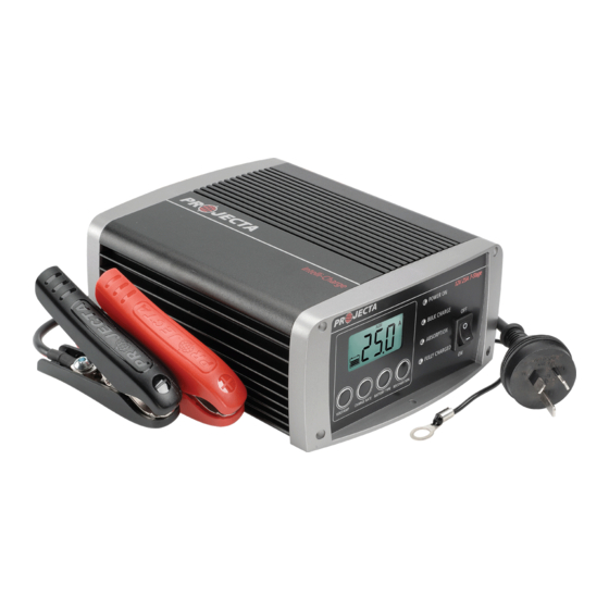
Page 20: Product Overview
VOLTS/AMPS CHARGE RATE BATTERY TYPE RECONDITION Charge Display & Charge Status Selection Buttons LEDs Power Cord DC Leads 12V 25A 7-Stage POWER ON IC800-24 IC2500 IC2500W TEMPERATURE REMOTE BULK CHARGE SENSOR ABSORPTION FULLY CHARGED VOLTS/AMPS CHARGE RATE BATTERY TYPE RECONDITION 12V 35A 7-Stage POWER ON... -
Page 21: Frequently Asked Questions
This can occur if a small amount of power is used for a long time, for example a map reading light is left on for a week or more. Projecta 7 Stage chargers are designed to charge from as little as as little as 2.5 Volts (12V) or 4.5 Volts (24V). - Page 22 Q. What if I have an appliance connected to the battery whilst charging? A. Powering an appliance while charging your battery will impact on the battery chargers ability to accurately measure the battery’s response to the charge being applied. The battery charger has been designed to accommodate this situation although not recommended.
- Page 23 NOTES:...
-
Page 24: Warranty Statement
WARRANTY STATEMENT Applicable only to product sold in Australia Brown & Watson International Pty Ltd of 1500 Ferntree Gully Road, Knoxfield, Vic., telephone (03) 9730 6000, fax (03) 9730 6050, warrants that all products described in its current catalogue (save and except for all bulbs and lenses whether made of glass or some other substance) will under normal use and service be free of failures in material and workmanship for a period of one (1) year (unless this period has been extended as indicated elsewhere) from the date of the original purchase by the consumer as marked on the...
Need help?
Do you have a question about the IC2500 and is the answer not in the manual?
Questions and answers