Table of Contents
Advertisement
Quick Links
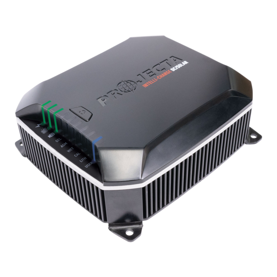
INTELLI-CHARGE
DC/SOLAR BATTERY CHARGER
25A, LINBUS, MULTI-CHEMISTRY
WARNING: This is a HIGH current device.
It is the installer's responsibility to ensure all cabling meets the
requirements as stipulated on page 6 of this installation manual to ensure a
SAFE installation, particularly when upgrading with a higher capacity unit.
Failure to comply with the supplied installation instructions will void the warranty.
P/No. IDC25X
Advertisement
Table of Contents

Related Manuals for Projecta IDC25X


Summary of Contents for Projecta IDC25X
- Page 1 It is the installer’s responsibility to ensure all cabling meets the requirements as stipulated on page 6 of this installation manual to ensure a SAFE installation, particularly when upgrading with a higher capacity unit. Failure to comply with the supplied installation instructions will void the warranty. P/No. IDC25X...
-
Page 2: Important Safety Information
TOUGH & RELIABLE • IDC25X is rated to IP68 & IP69K, ensuring it can withstand the toughest of conditions. All connections into the IDC25X are done via brass posts and crimped terminals. Ideal for mounting in the engine bay. IDC25X use temperature compensation to ensure the battery receives the correct charge voltage regardless of ambient temperatures. -
Page 3: Protective Features
50A. FUTURE PROOF • IDC25X was designed to stand the test of time. When IDC25X is paired with an Intelli- IQ, the firmware can be updated via Bluetooth ensuring IDC25X software is always up to date with the latest features. -
Page 4: Specifications
SPECIFICATIONS P/No. IDC25X Operating Conditions Alternator Input Voltage 9-32V Maximum Solar Input Voltage 32Vdc Maximum Input Current Input Current (No Load) INPUT: 9-11Vdc 20A Back Drain on Auxiliary Battery INPUT: 11-32Vdc 25A External LED Output – Constant Current Input Fuse Rating 50A (Not supplied) –... -
Page 5: Product Overview
PRODUCT OVERVIEW IDC25X LIN BUS Temperature 1 Auxiliary LED Input Terminal Input Input – Provision for auxiliary LED Terminal Terminal to indicate IDCX status Ignition Temperature 2 Input Input Terminal Terminal Power LED – Indicates Alternator IDCX on/off charging status Input Post Solar LED –... -
Page 6: Installation
System Memory Protector” be used. Connect the Auxiliary Battery positive (+) terminal to the IDC25X auxiliary battery output post. Fit at a fuse (50A for IDC25X) to the cable as close as possible to the Auxiliary Battery positive (+) terminal. - Page 7 Blade Terminal must be connected to the vehicle’s ignition. At 12.2V ALT voltage, the IDC25X will only operate when the vehicle’s ignition is turned on (may take up to 2 minutes to start charging). Fit a 1-2A fuse to the cable as close as possible to the vehicle’s ignition.
- Page 8 WIRING INSTRUCTION GUIDES FULL SYSTEM WITH INTELLI-IQ CONFIGURATION...
- Page 9 FULL SYSTEM CONFIGURATION...
- Page 10 ALTERNATOR/STARTER INPUT ONLY CONFIGURATION...
- Page 11 SOLAR & AUXILARY BATTERY INPUT CONFIGURATION...
- Page 12 HOW TO READ LED INDICATORS LED CHARGE INDICATORS DESCRIPTION Constant Green Solar Present Constant Green Alternator Present Constant Red IDC25X Faulty Constant Red Solar Input Reverse Polarity Constant Red Alternator Input Reverse Polarity Flashing Red Solar Overvoltage Flashing Red Alternator Overvoltage...
- Page 13 ALL BATTERY MODE LED’S FLASHING Output Short Circuit HOW TO SELECT BATTERY CHEMISTY IDC25X allows you to select the select the appropriate charge setting for your auxiliary battery. To change the battery type, hold and press the Mode Button ( ) for about 3 seconds.
-
Page 14: Frequently Asked Questions
This can occur if a small amount of power is used for a long time, for example a map reading light is left on for a week or more. The IDC25X is designed to charge an auxiliary battery from as little as 2 Volts. Refer to Page 13 Output... - Page 15 For this reason, the IDC25X will only output power when properly connected to a battery. To check if the IDC25X is functioning, follow the instructions to connect and operate the charger as normal on a flat battery. While the battery is charging measure the battery voltage with a volt or multi-meter.
-
Page 16: Warranty Statement
WARRANTY STATEMENT Brown & Watson International Pty. Ltd. (“BWI”) of 1500 Ferntree Gully Road, Knoxfield, Vic., telephone (03) 9730 6000, fax (03) 9730 6050, warrants that all products described in its current catalogue will under normal use and service be free of failures in material and workmanship for a period of five (5) year from the date of the original purchase by the customer as marked on the invoice (see elsewhere for specific warranty period).
Need help?
Do you have a question about the IDC25X and is the answer not in the manual?
Questions and answers