
Related Manuals for Projecta HDBC90


Summary of Contents for Projecta HDBC90
-
Page 1: Battery Charger
12/24V 70A MANUAL WORKSHOP BATTERY CHARGER P/No. HDBC90 HDBC90 Instruction Manual.indd 1 4/06/12 3:02 PM... -
Page 2: Important Safety Information
• Young children should be supervised to ensure that they do not play with the appliance. HDBC90 Instruction Manual.indd 2 4/06/12 3:02 PM... - Page 3 Automatically turns the battery charger off after a set time when charging your battery in Rapid Charge mode. POLARITY PROTECTION Fuse protection prevents damage to the charger in the event of reverse polarity and short circuit. HDBC90 Instruction Manual.indd 3 4/06/12 3:02 PM...
-
Page 4: Specifications
70.0A at 12V (rapid charge) 70.0A at 24V (rapid charge) ENGINE START 3 sec on, 2 min off 360A at 6V 360A at 12V MINIMUM START 0.0V VOLTAGE BACK DRAIN 5.5mA 11.6mA APPROVALS Electrical Safety, EMC HDBC90 Instruction Manual.indd 4 4/06/12 3:02 PM... -
Page 5: Battery Charger Assembly
BATTERY CHARGER ASSEMBLY Your HDBC90 is shipped with the following parts which require assembly to the main body of the battery charger unit: • 1 x Battery Charger Handle • 4 x 50mm Screws • 1 x Bottom Stabiliser Stop •... - Page 6 ASSEMBLING CHARGING LEADS TO BATTERY CLAMPS The HDBC90 battery charger is shipped with the battery clamps disconnected from the positive & negative charging leads. IMPORTANT: • The negative (Black) battery clamp must be connected to the charging lead connected to the unit.
-
Page 7: Charging Instructions
Connect the RED lead (battery clip) from the charger to the Positive (+) battery terminal. Connect the BLACK lead (battery clip) from the charger to the vehicle’s chassis away from the fuel line or moving parts. CONNECTION IN VEHICLE (NEGATIVELY EARTHED) HDBC90 Instruction Manual.indd 7 4/06/12 3:02 PM... - Page 8 Setting 1 (12V) 60–180 380–1080 520–1500 7–24 Setting 1 (24V) 75–220 460–1300 640–1830 7–24 Setting 2 (12V) 160–460 670–2800 1340–3800 7–24 Setting 2 (24V) 190–540 1130–3240 1600–4500 7–24 Setting 3 (12/24V) 420–1200 2500–7200 3500–1000 7–24 HDBC90 Instruction Manual.indd 8 4/06/12 3:02 PM...
- Page 9 Battery out of vehicle Remove the BLACK lead (battery clip) from the battery. Remove the RED lead (battery clip) from the battery. Battery in vehicle Remove the chassis connection. Remove the battery terminal connection. HDBC90 Instruction Manual.indd 9 4/06/12 3:02 PM...
- Page 10 NOTE: Do not repeat this operation more than 5 times. NOTE: When in engine start mode the HDBC90 uses increased power for a short period of time. Ensure other appliances connected to that power circuit are turned off to avoid fuse or circuit breaker overload in the buildings switchboard.
-
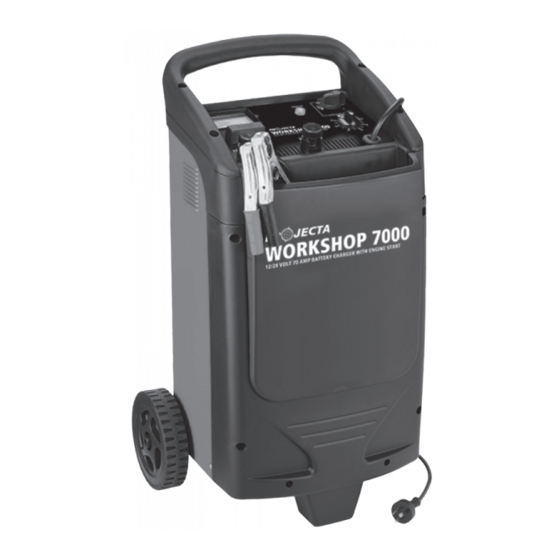
Page 11: Product Overview
PRODUCT OVERVIEW Positive Battery Clamp Negative Battery Clamp Trolley Wheels Bottom Stabiliser Stop 240V Mains Power Cord Power On Indicator Charge Meter Charge/Engine Start/Off Switch Output Fuse Charge Timer 12V/24V Terminals HDBC90 Instruction Manual.indd 11 4/06/12 3:02 PM... - Page 12 2. Disconnect battery charger leads from the vehicles battery. 3. Remove fuse cover on the top panel of the unit. 4. Remove and refit fuses (Projecta P/No. HDBCF100A) using a 10mm socket. 5. Refit fuse cover. HDBC90 Instruction Manual.indd 12...
-
Page 13: Frequently Asked Questions
Q. Can I use the charger as a power supply? A. No. The HDBC90 cannot be used as a power supply. Do not attempt to connect the clamps to anything other than a suitable battery. - Page 14 Again if you use the water analogy this would refer to how much water is flowing through the pipe. For example if the current is reading 12 Amps then this is the amount of energy going into the battery. HDBC90 Instruction Manual.indd 14 4/06/12 3:02 PM...
- Page 15 NOTES: HDBC90 Instruction Manual.indd 15 4/06/12 3:02 PM...
-
Page 16: Warranty Statement
National Toll Free 1800 113 443 NEW ZEALAND Narva New Zealand Ltd 22–24 Olive Road PO Box 12556 Penrose Auckland, New Zealand Telephone (09) 525 4575 IS166 Facsimile (09) 579 1192 Issue 2 1.6.12 HDBC90 Instruction Manual.indd 16 4/06/12 3:02 PM...
Need help?
Do you have a question about the HDBC90 and is the answer not in the manual?
Questions and answers