Samson 3374 Mounting And Operating Instructions
Electric actuator version with positioner, revision 2
Hide thumbs
Also See for 3374:
- Mounting and operating instructions (134 pages) ,
- Mounting and operation instructions (68 pages) ,
- Mounting and operating instructions (25 pages)

Related Manuals for Samson 3374


Summary of Contents for Samson 3374
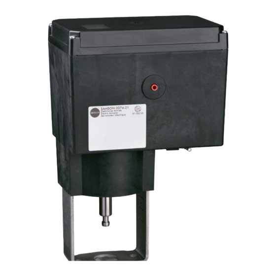
- Page 1 Type 3374 Electric Actuator Version with positioner, revision 2 Mounting and Operating Instructions EB 8331-4 EN Firmware version 2.04 Edition April 2014...
- Page 2 Definition of signal words DANGER! NOTICE Hazardous situations which, if not Property damage message or mal- avoided, will result in death or seri- function ous injury Note: WARNING! Additional information Hazardous situations which, if not avoided, could result in death or seri- Tip: ous injury Recommended action...
-
Page 3: Table Of Contents
Contents General safety instructions ................7 Design and principle of operation ..............8 Versions ......................8 Limit contacts ....................8 2.2.1 Mechanical limit contacts ................8 2.2.2 Electronic limit contacts ...................8 Technical data ....................9 Installation ....................12 Mounting position ..................12 Attachment to valve ..................13 3.2.1 Construction with integrated yoke ..............13 3.2.2 Construction with ring nut ................13 Electrical connections ...................15... - Page 4 Contents Operating level ...................31 12.1 Selecting operating mode ................31 12.2 Adapting the display ..................32 12.2.1 Reading direction ..................32 12.2.2 Backlight .....................32 12.3 Initializing the actuator .................33 12.4 Reading errors .....................34 12.5 Applications ....................35 12.5.1 Positioner ....................35 12.5.2 PID controller ....................35 12.5.3 Two-step mode ....................36 Configuration level ..................37...
- Page 5 Contents 15.4 Start initialization ..................54 15.5 Restarting the actuator (reset) ................54 15.6 Loading default settings ................54 15.7 Testing the display ..................55 15.8 Measuring the transit time ................56 Memory pen ....................57 16.1 Command pen .....................58 Appendix ....................60 17.1 Levels and customer data ................60 17.1.1 Operating level ....................60 17.1.2...
-
Page 7: General Safety Instructions
General safety instructions General safety instructions For your own safety, follow these instructions concerning the mounting, start up and opera- tion of the actuator: − The actuator is to be mounted, started up or operated only by trained and experienced personnel familiar with the product. -
Page 8: Design And Principle Of Operation
Design and principle of op- 2.1 Versions eration The Type 3374 Electric Actuator is available with or without fail-safe action. The Type 3374 Electric Actuator is used in industrial plants as well as in heating, venti- Version with fail-safe action lation and air-conditioning systems. Type 3374-2x and Type 3374-3x Actuators... -
Page 9: Technical Data
Design and principle of operation 2.3 Technical data Table 1: Version without fail-safe action Actuator Type 3374 Type of connection With yoke With ring nut Travel Travel limit Between 10 and 100 % of the rated travel Electrical connection Power supply 24 V AC ±15 %, 47 to 63 Hz 24 V DC ±15 % 85 to 264 V AC, 47 to 63 Hz Power consumption Speed level: Normal · Fast 12 VA ·... - Page 10 Design and principle of operation Table 2: Version with fail-safe action Actuator Type 3374 Type of connection With yoke With ring nut With yoke With ring nut Fail-safe action Stem extends Stem retracts Travel Travel limit Between 10 and 100 % of the rated travel Electrical connection Power supply 24 V AC ±15 %, 47 to 63 Hz...
- Page 11 Design and principle of operation Table 3: Common data Type 3374-xx Actuator Input signal Voltage input 0/2 to 10 V, adjustable · R = 20 kΩ Current input 0/4 to 20 mA, adjustable · R = 50 Ω Note: Only one of the two inputs may be connected.
-
Page 12: Installation
Installation Class of protection II according to EN 61140 Degree of contamination 2 according to EN 61010 Overvoltage category II according to EN 61010 Noise immunity According to EN 61000-6-2 Noise emission According to EN 61000-6-3 Mechanical environmental conditions Class 1M2 according to EN 60721-3-1:1998 Class 2M1 according to EN 60721-3-2:1998 Class 3M4 according to EN 60721-3-3:1998 Class 4M4 according to EN 60721-3-4:1998 Compliance... -
Page 13: Attachment To Valve
(8) is achieved. Lock this position nut (6) from the valve. with the lock nut (9). 2. Connect the power supply as described Types 3374-10/-11/-21/-31 in section 4 on page 15. Connection with yoke 3. Retract actuator stem (3) as described in Attachment to Series V2001 Valves, section 6. - Page 14 Installation 3. Connect the power supply as described Types 3374-15/-26/-36 in section 4. Connection with ring nut 4. Retract actuator stem (3) as described in Attachment to Series 240 Valves section 6. 5. Place actuator onto the valve bonnet (2.3) and secure using the ring nut (7).
-
Page 15: Electrical Connections
Electrical connections Electrical connections Establish electrical connections as illustrated in Fig. 4. Guide the cables to the plug-in ter- minals from the top. The following cables and DANGER! stranded wires can be used: Risk of electric shock For electrical installation, observe the Cable Cross section relevant electrotechnical regulations Single-wire H05(07) V-U 0.2 to 1.5 mm²... -
Page 16: Putting The Actuator Into Operation
Putting the actuator into operation Putting the actuator into op- Manual override eration The manual override is used to move the ac- tuator stem manually and is only available 1. Mount the actuator onto the valve. Refer for actuators without fail-safe action. to section 3.2. -
Page 17: Mechanical Limit Contacts
Mechanical limit contacts Mechanical limit contacts Installing limit contacts (Fig. 6 to Fig. 8): DANGER! 7.1 Installing the limit contacts Risk of electric shock When installing electrical equipment, Note: make sure the power supply is When ordering, state the configura- switched off and the signal input is tion ID (Var.-ID) and the type desig- disconnected first. - Page 18 Mechanical limit contacts 7. Slide the contact cam unit (21) onto the Note: spindle corresponding with the position To undo the screws on the housing of the actuator stem as illustrated in cover, use a Pozidriv PZ2 screwdriver Fig. 7. Make sure that the outermost cog to get enough hold on the screw of the contact cam unit engages in the heads.
- Page 19 Mechanical limit contacts Intermediate gear Spindle gear Serrated ring State on delivery: Tension spring Spindle (11) with Spacer serrated ring and shim 11 Spindle 12 Actuator board 13 Sleeve 17 Terminal board 18 Adjustment gear 21 Contact cam unit Fig. 8: Installing the limit contacts EB 8331-4 EN...
-
Page 20: Adjusting The Limit Contacts
Electronic limit contacts 7.2 Adjusting the limit contacts Electronic limit contacts Note: 8.1 Installing the limit contacts To undo the screws on the housing cover, use a Pozidriv PZ2 screwdriver Required accessories to get enough hold on the screw To install the electronic limit contacts, the ret- heads. -
Page 21: Adjusting The Limit Contacts
Electronic limit contacts 5. Adjust limit contacts as described in sec- tion 13.8. 6. Replace cover. Briefly turn the fastening screws counterclockwise with a screw- driver to center them. Then fasten down the cover by tightening the screws. 8.2 Adjusting the limit contacts The electronic limit contacts are adjusted at the operating controls of the actuator (refer to section 10). -
Page 22: Dimensions In Mm
Dimensions in mm Dimensions in mm Types 3374-10/-11/-21/-31 With actuator stem fully extended Type 3374 Dimension h EB 8331-4 EN... - Page 23 Dimensions in mm Types 3374-15/-26/-36 With actuator stem fully extended Type 3374 Dimension h Dimension h – – – – EB 8331-4 EN...
-
Page 24: Operating Controls
Operating controls 10 Operating controls Note: The operating controls are located underneath the housing cover. To undo the screws on the housing cover, use a Pozidriv PZ2 screwdriver to get enough hold on the screw heads. Display, refer to section 10.1 Rotary pushbutton, refer to section 10.2 Serial interface,... -
Page 25: Display
Operating controls 10.1 Display After switching on the power supply, the current firmware appears on the display for two seconds. Afterwards, the start screen appears. On starting up the actuator for the first time, the start screen and the error reading E00 (no initializa- tion performed) appear in alternating sequence. After start-up, the actuator is ready for use. Refer to section 5 on page 16. Fig. 10: Start screen after switching on the actuator for start-up Start screen The start screen (Fig. 11) depends on the selected application (refer to section 12.5 on page 35). On starting up the actuator for the first time and after loading the default set-... - Page 26 Operating controls Readings − Operating modes: automatic mode, manual mode − Bar graph: The bars indicate the system deviation that depends on the sign (+/–) and the value. One bar element appears per 1 % system deviation. Bar graph indicates a +3 % system Example: deviation. A maximum of five bar elements can appear on each side. Five bar elements indicate a system deviation ≥ 5 %.
-
Page 27: Rotary Pushbutton
Operating controls 10.2 Rotary pushbutton The rotary pushbutton is used for on-site operation of the actuator. Turn Select/change codes and values Press Confirm setting/change NOTICE Changed parameters are immediately effective! The process is directly affected by these changes. First check any changes made to parameters before confirming them by pressing the rotary pushbutton. -
Page 28: Serial Interface
TROVIS-VIEW provides a uniform user interface that allows users to configure and parameterize various SAMSON devices using device-specific database modules. The Type 3374 device module can be downloaded free of charge from our website (www. samson.de) at Services > Software > TROVIS-VIEW. Further information on TROVIS-VIEW (e.g. -
Page 29: Key Number
Key number 11 Key number Some parameters require the service key number to be entered before the parameter setting can be changed. If a code is selected without entering a key number beforehand, LOCK ap- pears on the display and the parameter settings cannot be changed. To enter the key number, proceed as follows: Note: ... -
Page 30: Customized Key Number
Key number 11.1 Customized key number A customized key number can be used in addition to the fixed service key number. Enter this key number in Code 9 as described for the service key number. The default key number is "0000". The customized key number can be changed in Code c92. If the customized key number is deactivated in Code c91, only the service key number is active. Code Description Adjustment range... -
Page 31: Operating Level
Operating level 12 Operating level The operating level is active while the actuator is in the automatic mode. In this level, import- ant information on the operation is shown, the operating mode is selected and the initializa- tion started. The other levels are accessible from the operating level. All the parameters of the operating level are listed in section 17.1.1 on page 60. -
Page 32: Adapting The Display
Operating level 12.2 Adapting the display 12.2.1 Reading direction To adapt the reading on the display to the mounting situation of the actuator, the display con- tents can be turned by 180° in Code 4. Code Description Adjustment range Change reading direction of display DISP DISP, 12.2.2 Backlight The display backlight can be changed to be always switched on in Code c93. -
Page 33: Initializing The Actuator
Operating level 12.3 Initializing the actuator WARNING! Risk of injury due to the actuator stem extending or retracting! Do not touch or block the actuator stem! NOTICE The process is disturbed by the movement of the actuator stem! Do not perform the initialization while the process is running! First isolate the plant by closing the shut-off valves! Initialization is performed with Code 5. During initialization, the actuator stem moves from its current position to the 100 % end position. Starting from the 100 % end position, the actu-... -
Page 34: Reading Errors
Operating level 12.4 Reading errors If an error has occurred, the start screen starts to blink and the icon appears. In the operat- ing level, the active errors appear on the display after Code 20. Note: − If several errors have occurred, only the error with the highest priority is shown on the start screen. -
Page 35: Applications
Operating level 12.5 Applications The actuator's application can be selected from one of the following applications: − Positioner − PID controller − Two-step mode 12.5.1 Positioner (06 = ACTU) The actuator stem's position directly follows the input signal. 12.5.2 PID controller (06 = PID) The set point adjustable at the actuator is used to position the valve using a PID algorithm. -
Page 36: Two-Step Mode
Operating level 12.5.3 Two-step mode (06 = OPEN) The binary input is used for this function. When the binary input is in the active switching state, the actuator stem retracts to 100 % of the adjusted travel range. When the binary input is in the inactive switching state, the actuator stem extends to move the valve to the closed position (0 %). -
Page 37: Configuration Level
Configuration level 13 Configuration level The actuator is adapted to its control task in the configuration level. The codes in this level have a 'c' prefix to identify them. Note: To change parameters in the configuration level, a service or customized key number must be entered first. Refer to section 11 on page 29. All the parameters of the configuration level are listed in section 17.1.2 on 61. 13.1 Activating and setting parameters Changing settings in the configuration level Activate the configuration level Turn à... -
Page 38: Input Signal
Configuration level 13.2 Input signal The input signal determines the actuator stem position. Either a current or voltage signal can be applied to the input. The default lower and upper range values of the input signal are 2 to 10 V or 4 to 20 mA. The input signal range can be adapted, e.g. to achieve a plant opera- tion characteristic by connecting two or more actuators in parallel (split-range operation). -
Page 39: Operating Direction
Configuration level Code Description Adjustment range Detect input signal failure NO (function not activated), YES (function activated) Reference value upon input signal failure INT INT (internal travel value), LAST (last travel value) Internal travel value 0.0 % 0.0 to 100.0 % 13.3 Operating direction −... - Page 40 Configuration level Mixing valve for mixing service For diverting service Flow pipe Flow pipe Return flow pipe Return flow pipe Diverting valve for mixing service For diverting service Flow pipe Flow pipe Return flow pipe Return flow pipe Fig. 14: Operating principle of three-way mixing and diverting valves Code Description Adjustment range Operating direction...
-
Page 41: End Position Guiding
Configuration level 13.4 End position guiding The actuator stem moves to the end positions early if the end position guiding function is ac- tive: 13.4.1 Operating direction increasing/increasing − End position guiding: valve open (c35): The actuator stem moves the valve to the top end position if the input signal reaches the value entered in this code. -
Page 42: Binary Input
Configuration level 13.5 Position feedback signal The position feedback indicates the actuator stem position. The span of the position feedback signal is adjusted over the lower and upper range value parameters. Note: − At least 2.5 V or 5 mA (depending on the input signal used) must separate the up- per and lower range values. -
Page 43: Binary Output
Configuration level − Next entry in information level (c11 = NEXT): If the NEXT function is selected in Code c11, the first code of the information level (i01) appears on the display as soon as binary input switching state is changed. After every new change to the active state, the next code of the information level appears (i02, i03 etc.). The display switches back to the start screen (Code 0 or Code 1 when PID controller is selected) after all the codes of the information level have been displayed due to the binary input switching or when the bi- nary input's switching state remains unchanged for five minutes. -
Page 44: Electronic Limit Contacts
Configuration level − Priority position (c15 = PRIO): When the priority position function is active (c11 = PRIO), this is registered at the binary output after the actuator stem stops moving. − Adopt binary input's state (c15 = BIN): The binary output reproduces the logical state of the binary input. -
Page 45: Restart
Configuration level Note: An activated limit contact remains permanently active if the switching value is smaller than the hysteresis. This limit contact can only be deactivated by a restart (refer to section 15.5) or by resetting to NONE (c24, c27). Code Description Adjustment range... -
Page 46: Blockage
Configuration level 13.10 Blockage Detect blockage (c51) The actuator detects a valve blockage by comparing the travel after the torque-dependent switch has been triggered with the travel measured on initialization. If the comparison shows that the limit switch was triggered too early, this indicates that there is a valve blockage. A blockage is indicated on the display by . -
Page 47: Characteristic
Configuration level Speed level (c64) The actuator stem moves to the position determined by the input signal at the selected strok- ing speed. There are two different speed levels (NORM and FAST). The transit time (c66) is calculated from the travel and the stroking speed (c65). The transit time is the time that the actuator stem needs to move through the adjusted travel. - Page 48 Configuration level − Linear (c71 = LIN): The travel is proportional Travel y [%] to the input signal. Input signal x [%] − Equal percentage (c71 = EQUA): The travel Travel y [%] is exponential to the input signal. Input signal x [%] − Reverse equal percentage (c71 = INV): The Travel y [%] travel is reverse exponential to the input sig- nal.
- Page 49 Configuration level Code Description Adjustment range Characteristic type LIN (linear), EQUA (equal percentage), INV (reverse equal percentage), USER (user-defined) When c71 = USER: c72 = USE User-defined characteristic H0, Y0 Input signal X0, travel value Y0 0.0 % 0.0 to 100.0 % H1, Y1 Input signal X1, travel value Y1 10.0 % 0.0 to 100.0 % H2, Y2...
-
Page 50: Information Level
Information level 14 Information level In the information level, all the actuator data important for closed-loop operation are dis- played. Codes of the information level have an 'i' prefix to identify them. All the parameters of the information level are listed in section 17.1.3 on page 66. 14.1 Activating parameters Activate the information level Display: Code 0... -
Page 51: Diagnostic Level
Diagnostic level 15 Diagnostic level The diagnostic level contains detailed information on the actuator and its operating state. Additionally, various test functions can be performed in this level. Codes in the diagnostic level have a 'd' prefix to identify them. All the parameters of the diagnostic level are listed in section 17.1.4 on page 67. EB 8331-4 EN... -
Page 52: Activating And Setting Parameters
Diagnostic level 15.1 Activating and setting parameters Activate the diagnostic level Display: Code 0 Turn à Code 20 Press (display: d01) Activating parameters Turn à Required code Setting parameters Press (blinking display) Turn à Required setting Press (to confirm setting) Exit diagnostic level Turn à... -
Page 53: Troubleshooting
Blockage (only when c51 = YES) Check attachment and valve, if necessary. Check actuator stem. d23* Both limit switches active Send actuator to SAMSON d24* Canceled while retracting stem Send actuator to SAMSON d25* Canceled while extending stem Send actuator to SAMSON... -
Page 54: Start Zero Calibration
Diagnostic level 15.3 Start zero calibration WARNING! Risk of injury due to the actuator stem extending or retracting! Do not touch or block the actuator stem! The actuator stem moves to the 0 % end position. Following this, the actuator changes to closed-loop operation and moves the actuator stem to the position defined by the input sig- nal. Code Description Adjustment range Start zero calibration 15.4 Start initialization The procedure is described in section 12.3 on page 33. 15.5 Restarting the actuator (reset) The actuator can be restarted by performing a reset. -
Page 55: Testing The Display
Diagnostic level 15.7 Testing the display All the segments of the display are shown during the display test when a display functions properly. The display test is performed by selecting Code d55 in the diagnostic level (Code 20). Activate display test (Diagnostic level/Code 20) Turn à... -
Page 56: Measuring The Transit Time
Diagnostic level 15.8 Measuring the transit time WARNING! Risk of injury due to the actuator stem extending or retracting! Do not touch or block the actuator stem! NOTICE The process is disturbed by the movement of the actuator stem! Do not perform the initialization while the process is running! First isolate the plant by closing the shut-off valves! During transit time measurement, the actuator stem moves from its current position to the 0 % end position. Starting from the 0 % end position, the actuator stem moves to the 100 % end... -
Page 57: Memory Pen
The memory pen is optional (accessories) and is used to store and transfer data: − Memory pen-64 (order no. 1400-9753) The memory pen can be configured in TROVIS-VIEW. The following functions for the Type 3374 Actuator can be selected: − Read data from the memory pen − Write data to the memory pen − Time-controlled data logging −... -
Page 58: Command Pen
Memory pen Table 4: Memory pen dialog Code Function Action Text Read data from memory pen Read READ Write WRIT Write data to memory pen Write WRIT Time-controlled data logging Data logging in progress TLOG Event-triggered data logging Data logging in progress ELOG Table 5: Memory pen error Code Error... - Page 59 Memory pen Using the command pen 1. Open the actuator cover. 2. Insert the command pen into the serial interface of the actuator. Ö The actuator automatically recognizes the command pen. The dialog for the command pen appears on the display. The function (command) selected in TROVIS-VIEW is repre- sented by a code on the display (see Table 6).
-
Page 60: Appendix
Appendix 17 Appendix 17.1 Levels and customer data 17.1.1 Operating level Code Parameters Select (select ESC to cancel) Section Start screen Actuator travel – Read only – [%] 10.1 Operating level Positioning value – Read only – [%] Select the operating mode AUTO (automatic mode), 12.1 MAN (manual mode) Set manual position value 0.0 to 100.0 % 12.1 Change reading direction of display... -
Page 61: Configuration Level
Appendix 17.1.2 Configuration level Code Parameters Setting range Section Customer (select ESC to cancel) data Input signal c01 Unit mA (current signal), 13.2 V (voltage signal) c02 Lower range value 0.0 to 15.0 mA 4.0 mA 13.2 0.0 to 7.5 V 2.0 V c03 Upper range value 5.0 to 20.0 mA... - Page 62 Appendix Code Parameters Setting range Section Customer (select ESC to cancel) data Electronic limit contact (binary output) c21 Message in case of event NONE (inactive), NONE 13.7 HIGH (upper limit violation), LOW (lower limit violation) c22 Switching value 0.0 to 100.0 % 10.0 % 13.7 c23 Hysteresis 0.0 to 10.0 % 1.0 % 13.7...
- Page 63 Appendix Code Parameters Setting range Section Customer (select ESC to cancel) data c43 Restart NORM (normal), NORM 13.9 ZERO (zero calibration), FIX (fixed positioning value), STOP (stop in manual level) c44 Fixed positioning value on 0.0 to 100.0 % 0.0 % 13.9 restart Blockage c51 Blockage detection NO (function not activated), 13.10 YES (function activated)
- Page 64 Appendix Code Parameters Setting range Section Customer (select ESC to cancel) data PID controller c81 Set point 0.0 to 100.0 % 50.0 % 13.6, 12.5 c82 Proportional-action 0.1 to 50.0 12.5 coefficient Kp c83 Reset time Tn 0 to 999 s 20 s 12.5 c84 Derivative-action time Tv 0 to 999 s 12.5 Scaling of the set point for PID controller...
- Page 65 Appendix Characteristic level Code Parameters Selection Section Customer data 0.0 to 100.0 % 0.0 % 13.12 0.0 to 100.0 % 0.0 % 13.12 0.0 to 100.0 % 10.0 % 13.12 0.0 to 100.0 % 10.0 % 13.12 0.0 to 100.0 % 20.0 % 13.12 0.0 to 100.0 % 20.0 % 13.12 0.0 to 100.0 % 30.0 % 13.12 0.0 to 100.0 % 30.0 % 13.12 0.0 to 100.0 % 40.0 % 13.12 0.0 to 100.0 % 40.0 % 13.12 0.0 to 100.0 % 50.0 % 13.12 0.0 to 100.0 %...
-
Page 66: Information Level
Appendix 17.1.3 Information level Code Parameters (read only) Reading/unit Section Input signal Lower range value of input signal [V] or [mA] 13.2 Upper range value of input signal [V] or [mA] 13.2 Input signal 13.2 Input signal [V] or [mA] 13.2 Travel Actuator travel... -
Page 67: Diagnostic Level
Appendix 17.1.4 Diagnostic level Code Parameters Display/select (select ESC to cancel) Section Information – Device Firmware version – Read only – Revision number – Read only – Errors – Status Error during operation – Read only – YES, Priority position triggered Errors –... - Page 68 Appendix Code Parameters Display/select (select ESC to cancel) Section Test – Transit time Start transit time measurement 15.8 Measured transit time – Read only – [s] 15.8 Measured travel – Reading only – [mm] 15.8 Speed level during measurement – Read only – 15.8 NORM (normal), FAST (fast)
-
Page 69: Further Codes On The Display
Appendix 17.1.5 Further codes on the display Code Function State Text Zero calibration ZERO Active, select ESC to cancel Initialization Active, select ESC to cancel INIT Transit time measurement Active, select ESC to cancel Long-term test Active, select ESC to cancel Blocking protection Active BPRO... -
Page 70: Nameplate
Appendix 17.2 Nameplate Configuration ID (Var.-ID) SAMSON 3374-15 Serial number Elektrischer Antrieb Testing according to Electric Actuator Servomoteur électrique DIN EN 14597 Var-ID Serial no. Power supply Power consumption Power line frequency Nominal transit time Stroking speed Digital positioner Firmware V Thrust (stem retracts) 0(4)...20 mA DC;... -
Page 71: Replacing The Display
Appendix 17.4 Replacing the display EB 8331-4 EN... - Page 72 Appendix EB 8331-4 EN...
- Page 73 Appendix Keep pressed EB 8331-4 EN...
- Page 74 Appendix EB 8331-4 EN...
- Page 75 Appendix EB 8331-4 EN...
- Page 76 Appendix EB 8331-4 EN...
- Page 77 EB 8331-4 EN...
- Page 78 EB 8331-4 EN...
- Page 79 Index Index Default settings ........54 Design ........... 8 Diagnostic level .... 51–55, 55, 67–68 Actuator measuring the transit time ....56 mounting on valve ......12 parameters ........52 principle of operation ......8 restarting actuator ......54 restarting ........54 testing the display ......
- Page 80 Index Manual level ........43 Technical data ......9–12, 22 Manual override ........16 Testing according to DIN EN 14597 ..8 Memory pen ........57 Transit time ........47, 56 Menu control ........27 Travel ..........46 Troubleshooting ........53 Nameplate ..........
- Page 81 Service key number 1732...
- Page 83 EB 8331-4 EN...
- Page 84 SAMSON AG · MESS- UND REGELTECHNIK Weismüllerstraße 3 · 60314 Frankfurt am Main, Germany Phone: +49 69 4009-0 · Fax: +49 69 4009-1507 EB 8331-4 EN samson@samson.de · www.samson.de...
Need help?
Do you have a question about the 3374 and is the answer not in the manual?
Questions and answers