Table of Contents

Related Manuals for Samson 3214


Summary of Contents for Samson 3214
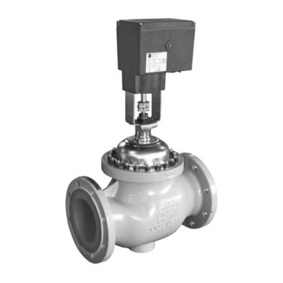
- Page 1 Electric Control Valves Types 3214/3374, 3214/3274 Type 3214 Globe Valve balanced by a diaphragm Type 3214/3374 Type 3214 Globe Valve balanced by a diaphragm Mounting and Operating Instructions EB 5868-1 EN Edition September 2006...
-
Page 2: Table Of Contents
Contents Contents Design and principle of operation ....4 Versions ....... . 4 Technical data . - Page 3 General safety instructions General safety instructions The control valve is to be mounted, started up or serviced by fully trained and qualified personnel only, observing the accepted industry codes and practices. Make sure employees or third persons are not exposed to any danger.
-
Page 4: Design And Principle Of Operation
(EB). The downstream pressure p is applied to ** Type 3274-23 Actuator with fail-safe func- the inside of the Type 3214 Valve; the up- tion: typetesting available on request stream pressure p acts on the outside. The... - Page 5 5 Rod-type yoke 6 Plug stem 7 Coupling nut 8 Actuator 9 Hex nut 10 Coupling nut 11 Adapter 12 Hex nut Type 3214/3274 Fig. 1 · Principle of operation: Type 3214/3374 (top) · Type 3214/3274 (bottom) EB 5868-1 EN...
-
Page 6: Technical Data
Design and principle of operation 1.2 Technical data 1. Type 3214 Globe Valve balanced by a diaphragm Nominal size Rated travel Max. perm. diff. pressure Δp Max. perm. temperature °C 150 (version for water) · 80 (version for non-flammable gases) Materials ·... -
Page 7: Installation
Installation Installation 2.2 Strainer Install the strainer upstream of the control 2.1 Mounting position valve. Make sure the direction of flow corre- sponds to the arrow on the valve body. Install the valve in upright position into a The filter element must be vertically sus- horizontal pipeline. -
Page 8: Assembling Valve And Actuator
Assembling valve and actuator Assembling valve and Electrical connections actuator Upon installation of the electrical con- If the valve and actuator have not already nections, observe the regulations con- been assembled by the manufacturer, or if cerning electrical power plant systems the original actuator of a control valve is to according to DIN VDE 0100 as well as be replaced by a different type or size, re-... - Page 9 Electrical connections If voltage is applied to aL, the actu- Type 3374 Actuator ator stem is extended (”Actuator 1. Remove the housing cover. stem extends“). 2. Route the connecting cables through the Actuators operated in parallel must be cable entries onto the terminals and fas- controlled using separate contacts as us- ten them.
- Page 10 Electrical connections 3. Connect grounding conductors to the Type 3274 Actuator separate grounding conductor terminals 1. Remove the housing cover on the side. on the inside of the housing. 2. Route the connecting cables through the 4. Remount the housing cover. cable entries on the housing onto the ter- Fuse: minals and fasten them.
-
Page 11: Operation - Manual Override
Operation – manual override Version with electrical override – Operation – manual override Type 3274-23 The two pushbuttons on the side of the hous- Type 3374 Actuator ing cover can be used to retract or extend The travel is adjusted on the red trunnion at the actuator stem and thus move the control the side of the housing using a 4 mm hexa- valve to the desired travel position. -
Page 12: Opening Isolating Terminal 81 (Type 3274)
Operation – manual override To re-establish the priority of the controller 5.1 Opening isolating terminal 81 signal, proceed as follows: (Type 3274) Switch off the voltage supply and remove 1. Switch off the voltage supply! the cover. Firmly press the release button until it 2. -
Page 13: Maintenance
Maintenance Maintenance The control valves are maintenance free. Nevertheless, they are subject to natural wear, particularly at the seat, plug, and packing. Depending on the operating condi- tions, the valves need to be checked at regu- lar intervals to avoid possible malfunctions. If external leaks occur, check the packing or balancing diaphragm and, if necessary, re- place them. -
Page 14: Dimensions In Mm And Weights
Dimensions in mm and weights Dimensions in mm and weights Nominal size Length L Height H1 Height H Type 3214/3274-12 Type 3214/3274-16 Type 3214/3274-23 Type 3214/3374-10 Weight (approx.) Type 3214/3274 Type 3214/3374 Valves in PN 16; add 15 % for PN 25 and PN 40... - Page 15 EB 5868-1 EN...
- Page 16 SAMSON AG · MESS- UND REGELTECHNIK Weismüllerstraße 3 · 60314 Frankfurt am Main · Germany Phone: +49 69 4009-0 · Fax: +49 69 4009-1507 EB 5868-1 EN Internet: http://www.samson.de...
Need help?
Do you have a question about the 3214 and is the answer not in the manual?
Questions and answers