Samson 3372 Mounting And Operating Instructions
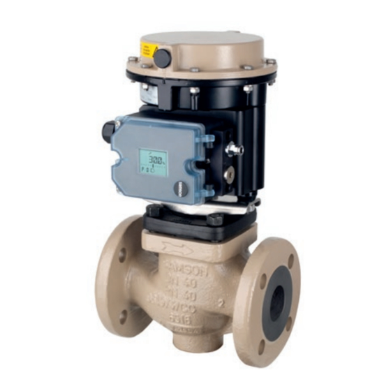
Electropneumatic actuator with type 3725 positioner. actuator area: 120 and 350 cm2
Hide thumbs
Also See for 3372:
- Mounting and operating instructions (60 pages) ,
- User manual (8 pages) ,
- Mounting and operating instructions (76 pages)
Table of Contents

Related Manuals for Samson 3372


Summary of Contents for Samson 3372
- Page 1 EB 8313-3 EN Translation of original instructions Type 3372 with 120 cm² actuator area Type 3372 with 350 cm² actuator area Type 3372 Electropneumatic Actuator Actuator area: 120 and 350 cm² With Type 3725 Positioner Edition September 2019...
- Page 2 Note on these mounting and operating instructions These mounting and operating instructions assist you in mounting and operating the device safely. The instructions are binding for handling SAMSON devices. The images shown in these instructions are for illustration purposes only. The actual product may vary.
-
Page 3: Table Of Contents
Contents Safety instructions and measures ..............1-1 Notes on possible severe personal injury ............1-4 Notes on possible personal injury ..............1-5 Notes on possible property damage .............1-6 Markings on the device ................2-1 Actuator nameplate ..................2-1 Label indicating actuator with preloaded springs ...........2-2 Design and principle of operation ...............3-1 Direction of action ..................3-1 Signal pressure routing ................3-4... - Page 4 Removal ....................11-1 11.1 Removing the actuator from the valve ............11-2 11.2 Relieving the spring compression in the actuator ..........11-3 Repairs ....................12-1 12.1 Returning devices to SAMSON ..............12-1 Disposal ....................13-1 Certificates ....................14-1 Annex......................15-1 15.1 Tightening torques, lubricants and tools ............15-1 15.2 Spare parts ....................15-1...
-
Page 5: Safety Instructions And Measures
SAM- SON. SAMSON does not assume any liability for damage resulting from the failure to use the de- vice for its intended purpose or for damage caused by external forces or any other external factors. - Page 6 Î Check with the plant operator for details on further protective equipment. Revisions and other modifications Revisions, conversions or other modifications of the product are not authorized by SAMSON. They are performed at the user's own risk and may lead to safety hazards, for example.
- Page 7 Î Observe the maximum permissible values specified in the certificates for intrinsically safe circuits. Referenced standards and regulations The Type 3372 Electropneumatic Actuator fulfills the requirements of the Directives 2014/30/EU and 2014/34/EU. The 'Certificates' section contains this declaration of con- formity.
-
Page 8: Notes On Possible Severe Personal Injury
Safety instructions and measures Referenced documentation The following documents apply in addition to these mounting and operating instructions: − u EB 8394 for the mounted Type 3725 Positioner − Mounting and operating instructions for the mounted valve − Mounting and operating instructions for mounted valve accessories (e.g. u EB 8367 for Type 4744 Limit Switch) −... -
Page 9: Notes On Possible Personal Injury
Safety instructions and measures 1.2 Notes on possible personal injury WARNING Crush hazard arising from moving parts. The actuator contains moving parts (actuator stem), which can injure hands or fingers if inserted into the actuator. Î Do not touch the actuator stem or insert hands or finger into the yoke or beneath the actuator stem while the air supply is connected to the actuator. -
Page 10: Notes On Possible Property Damage
Safety instructions and measures WARNING Risk of personal injury through incorrect operation, use or installation as a result of information on the actuator being illegible. Over time, markings, labels and nameplates on the actuator may become covered with dirt or become illegible in some other way. As a result, hazards may go unnoticed and the necessary instructions not followed. - Page 11 Risk of actuator damage due to the use of unsuitable tools. Certain tools are required to work on the actuator. Î Only use tools approved by SAMSON (u AB 0100). Risk of actuator damage due to the use of unsuitable lubricants. The lubricants to be used depend on the actuator material. Unsuitable lubricants may corrode and damage the surface.
- Page 12 EB 8313-3 EN...
-
Page 13: Markings On The Device
Fig. 2-1: Nameplate position on the Type 3372 Actuator SAMSON 3372 actuator cm² See technical data for ambient temperature Model 3372- Var-ID Serial no. Air supply max. Made in Germany SAMSON AG D-60314 Frankfurt Fig. 2-2: Nameplate of Type 3372 Actuator with Type 3725 Positioner (direct attachment) EB 8313-3 EN... -
Page 14: Label Indicating Actuator With Preloaded Springs
Markings on the device 2.2 Label indicating actuator with preloaded springs A label on the actuator indicates that the actuator springs are preloaded in the delivered state (see Fig. 2-3). ACHTUNG ! ATTENTION ! ATTENTION ! VORGESPANNTER PRE-LOADED SERVO-MOTEUR ANTRIEB ACTUATOR PRECONTRAINT Fig. 2-3: Adhesive label indicating preloaded actuator springs in the delivered state EB 8313-3 EN... -
Page 15: Design And Principle Of Operation
120 or tion is fixed at the ordering stage and cannot 350 cm². They are mainly used for attach- be changed. ment to SAMSON Series V2001 Valves: − Type 3321 Globe Valve Actuator stem extends (FA) − Type 3323 Three-way Valve With direction of action "actuator stem ex-... - Page 16 A16 Top diaphragm case Actuator stem A17 Crossbeam A10 Spring A18 Diaphragm A11 Rod A25 Rod nut A13 Diaphragm plate A26 Collar nut A14 Diaphragm plate A30 Stem connector clamps Fig. 3-1: Type 3372 with 120 cm² actuator area and crossbeam EB 8313-3 EN...
- Page 17 A27 Compressor A54 Rod nut Actuator stem A33 Stem A60 Plate A10 Spring A40 Radial shaft seal A61 Support element A15 Collar nut A41 Wiper ring Signal pressure connection (stem retracts) Fig. 3-2: Type 3372 with 350 cm² actuator area EB 8313-3 EN...
-
Page 18: Signal Pressure Routing
Design and principle of operation 3.2 Signal pressure routing 3.3 Fail-safe action The signal pressure of the mounted When the signal pressure is reduced or the Type 3725 Positioner is routed through the control signal fails, the fail-safe position of corresponding port in the support element. the control valve (see section 3.1) depends on whether the springs are installed in the Actuator stem extends (FA) -
Page 19: Version With Direction Of Action "Stem Retracts
Design and principle of operation 3.3.2 Version with direction of action "stem retracts" When the signal pressure is reduced or the control signal fails, the springs move the ac- tuator stem upward and open a mounted globe valve. The valve closes when the signal pressure is increased enough to overcome the spring force. -
Page 20: Versions
15 to 80 4 to 80 3.5 Versions directions of action (stem extends or re- tracts). − Standard version of Type 3372 The travel stop is not available for (120 cm²) Type 3372 (350 cm²). The housings of Type 3372 Electropneu- − Version with handwheel (120 cm²) matic Actuators have an actuator area of The Type 3372 Actuators (120 cm²) can... -
Page 21: Technical Data
350 cm² actuator areas (u AB 0100). Reducing station for supply air Compliance The reducing station for supply air can be di- The Type 3372 Pneumatic Actuator with rectly attached when combined with a Type 3725 Positioner (direct attachment) Type 3730 Positioner. All other reducing sta- bears the CE and EAC marks of conformity. - Page 22 Design and principle of operation Table 3-3: Ex approvals Type 3372 With Type 3725 Positioner (direct attachment) Actuator area 120 cm² 350 cm² Rated travel 15 mm 15 mm 30 mm Number PTB 11 ATEX 2020 X ATEX Date 2011-08-25 Type of protection II 2G Ex ia IIC T4 Number 2703735 X CSA Group Date 2014-06-03 Ex ia IIC T4;...
- Page 23 Design and principle of operation Table 3-4: Technical data Actuator area 120 cm² 350 cm² 0.4 to 2.1 to 1.5 to 2.1 to 1.5 to 2.2 to Bench range in bar 1.4 to 2.3 Fail-safe action Stem Stem Stem Stem Stem Stem Stem Stem retracts...
- Page 24 3-10 EB 8313-3 EN...
-
Page 25: Shipment And On-Site Transport
Shipment and on-site transport 4 Shipment and on-site trans- Î Dispose and recycle the packaging in ac- cordance with the local regulations. port 4.3 Transporting and lifting the The work described in this section is only to be performed by personnel qualified for the actuator assignment accordingly. -
Page 26: Lifting The Actuator
Î Observe the storage instructions. Î Avoid long storage times. Special storage instructions for elastomers Î Contact SAMSON in case of different Elastomer, e.g. actuator diaphragm storage conditions or long storage peri- − To keep elastomers in shape and to pre- ods. -
Page 27: Mounting And Assembly
5.2 Mounting the device Î The following regulations apply to instal- lation in hazardous areas: EN 60079-14 Depending on the version, SAMSON control (VDE 0165, Part 1). valves are either delivered with the actuator Î Work must only performed by personnel... -
Page 28: Mounting The Actuator Onto The Valve
Risk of actuator damage due to the use of ator stem. unsuitable tools. Î Do not touch the actuator stem or insert Î Only use tools approved by SAMSON hands or finger into the yoke while the (u AB 0100). air supply is connected to the actuator. - Page 29 Mounting and assembly a) 120 cm² version 5. Fail-safe action "stem extends": position the stem connector clamps (A30) and screw them tight. Observe tightening Mounting using crossbeam (form B, see torques. Fig. 5-1) Fail-safe action "stem retracts": apply pressure to the top diaphragm chamber NOTICE until the actuator stem touches the plug The actuator can be damaged.
- Page 30 Mounting and assembly Mounting using rods (form C, see Fig. 5-2) 1. Remove the stem connector clamps (A29) from the actuator. 2. Insert the rods (A11) into the bushings (A9) and place them in the correspond- ing holes on the valve bonnet (2). 3.
- Page 31 Mounting and assembly b) 350 cm² version 5. Fail-safe action "stem extends": position the stem connector clamps (A12) and screw them tight. Observe tightening Mounting using rods (form C, see Fig. 5-3) torques. 1. Remove the clamps of the stem connector Fail-safe action "stem retracts": apply (A12) from the actuator.
-
Page 32: Connections
Mounting and assembly 5.3 Connections The actuator is fitted with M20x1.5 black plastic cable glands and a pneumatic con- necting plate G ¼ as standard. Î If other connections are required, use the accessories listed in the mounting and operating instructions of the positioner (e.g. -
Page 33: Start-Up
Start-up 6 Start-up WARNING The work described in this section is only to Risk of personal injury due to preloaded be performed by personnel qualified for the springs. assignment accordingly. Actuators with preloaded springs are under tension. These actuators can be identified by several longer bolts with nuts protruding DANGER from the bottom diaphragm case. -
Page 34: Preloading The Springs
Start-up Î Before unblocking the actuator stem after − In combination with a SAMSON valve: it has become blocked (e.g. due to seiz- the actuator travel range can be adapted ing up after remaining in the same posi- to a smaller valve travel range tion for a long time), release any stored 6.1.1... -
Page 35: Increasing The Actuator Thrust
1.65 bar and the new upper signal range action cannot be preloaded. When a value 2.25 bar. SAMSON valve is combined with an oversized actuator (e.g. the rated travel of Î Write the new signal pressure range of the actuator is larger than the rated travel of 1.65 to 2.25 bar on the actuator name-... - Page 36 Start-up Hex bolt Hex nut Hex bolt (preloading) Washer Fig. 6-1: Type 3372 with 350 cm² actuator area and clamping bolts A100 A104 Spindle A100 Cover A101 Lock nut A101 A102 Top diaphragm case A104 Lock nuts A102 Fig. 6-2: Travel stop for 120 cm² version...
-
Page 37: Bottom Travel Stop (Minimum Travel)
2. Loosen the lock nuts (A104). 3. Move actuator to the position of mini- The Type 3372 Electropneumatic Actuator mum travel. (120 cm²) can optionally fitted with a hand- 4. Screw the bottom nut (A104) on as far wheel. -
Page 38: Operating The Handwheel Of Version With "Stem Retracts" Direction Of Action
Start-up 6.3.2 Operating the hand- wheel of version with "stem retracts" direction of action 1. Turn the handwheel clockwise. The actu- ator stem extends causing a globe valve to close. 2. Extend the actuator stem up to the re- quired position. Upper actuator section Spindle Cover... -
Page 39: Operation
7.1 Throttling service Risk of personal injury due to exhaust air being vented. The Type 3372 Pneumatic Actuator is de- The actuator is operated with air. As a result, signed for a maximum supply pressure of air is vented during operation. -
Page 40: Manual Mode (Versions With Handwheel Only)
7.4 Additional notes con- Version with direction of action "actuator stem retracts" cerning operation With fail-safe action "actuator stem retracts Î Label actuators with reduced supply (FE)", the permissible supply pressure must pressure with a sticker ("Max. supply not exceed the upper bench range value by pressure limited to ... -
Page 41: Malfunctions
Malfunctions 8 Malfunctions 8.1 Troubleshooting Malfunction Possible reasons Recommended action Actuator stem does not Actuator is blocked. Check attachment. move on demand. Unblock the actuator. WARNING! A blocked actuator (e.g. due to seizing up after remaining in the same position for a long time) can suddenly start to move uncontrollably. -
Page 42: Emergency Action
Malfunctions 8.2 Emergency action The plant operator is responsible for emer- gency action to be taken in the plant. EB 8313-3 EN... -
Page 43: Service And Conversion Work
Service and conversion work 9 Service and conversion work Î Depressurize all plant sections concerned and the actuator. Release any stored en- The work described in this section is only to ergy. be performed by personnel qualified for the assignment accordingly. WARNING The following documents are also necessary for servicing the valve:... -
Page 44: Periodic Testing
(e.g. spring Î Only use tools approved by SAMSON compression). See 'Relieving the spring (u AB 0100). compression in the actuator' in the 'Removal' section. -
Page 45: Preparing The Valve For Service Work
Service and conversion work − Replace the diaphragm (see sec- tion 9.4.1). Our after-sales service can support you in − Replace the actuator stem seals (see sec- drawing up an inspection and test plan for tion 9.4.2). your plant. 9.3 Mount the valve after ser- 9.2 Preparing the valve for vice work service work... - Page 46 Service and conversion work Version with direction of action Version with direction of action "actuator stem retracts" "actuator stem extends" Bottom diaphragm case A16 Top diaphragm case Actuator stem A17 Crossbeam A10 Spring A18 Diaphragm A11 Rod A25 Rod nut A13 Diaphragm plate A26 Collar nut A14 Diaphragm plate...
- Page 47 A27 Compressor A54 Rod nut Actuator stem A33 Stem A60 Plate A10 Spring A40 Radial shaft seal A61 Support element A15 Collar nut A41 Wiper ring Signal pressure connection (stem retracts) Fig. 9-2: Type 3372 with 350 cm² actuator area EB 8313-3 EN...
-
Page 48: Service Work
Service and conversion work 9.4 Service work 8. Apply a suitable lubricant to the actuator stem (A3). See Fig. 9-2 and Fig. 9-1 9. Place the actuator stem (A3) together with the diaphragm plate (A14), dia- 9.4.1 Replacing the dia- phragm (A18) and diaphragm plate phragm (A13) in the bottom diaphragm case (A2). - Page 49 Service and conversion work 8. Check whether the springs (A10) rest 6. Place the compressor (A27) onto the ac- correctly in the bottom diaphragm case tuator stem (A7). (A2). 7. Check the sealing element on the collar 9. Apply a suitable lubricant to the actuator nut (A15).
-
Page 50: Replacing The Actuator Stem Seals
Service and conversion work a) 120 cm² version 5. Place the new diaphragm on the dia- phragm plate (A5). 6. Place the compressor (A27) onto the ac- Version with direction of action "actuator tuator stem (A7). stem extends" 7. Check the sealing element on the collar 1. - Page 51 Service and conversion work 12. Fasten the top and bottom diaphragm Version with direction of action "actuator cases (A16, A2) together using the nuts stem retracts" (A24) and bolts (A22). Place on the 1. Lift off the top diaphragm case (A16). screw-on cap (A21).
- Page 52 Service and conversion work 7. Fill the cavity of the radial shaft seal, in 4. Check the dry bearing (A2.4) and wiper which the spring is seated, with lubri- (A2.3) and renew them, if necessary. cant. 5. Apply a suitable lubricant to the seal lip 8.
- Page 53 Service and conversion work 3. Use a suitable tool to remove the radial 10. Insert the actuator stem (A7) together shaft seal (A40) from the bottom case with the diaphragm plate (A5) and dia- (A2). phragm (A4) into the bottom diaphragm case (A2).
-
Page 54: Conversion Work
9.5.1 Reversing the direction Contact your nearest SAMSON subsidiary of action (fail-safe ac- or SAMSON's after-sales service for infor- tion) mation on spare parts, lubricants and tools. Spare parts The direction of action (and fail-safe action) of the Type 3372 Electropneumatic Actuator See the Annex for details on spare parts. -
Page 55: Decommissioning
Decommissioning 10 Decommissioning WARNING The work described in this section is only to Risk of personal injury due to preloaded be performed by personnel qualified for the springs. assignment accordingly. Actuators with preloaded springs are under tension. These actuators can be identified by several longer bolts with nuts protruding DANGER from the bottom diaphragm case. - Page 56 Decommissioning Î Before unblocking the actuator stem after it has become blocked (e.g. due to seizing up after remaining in the same position for a long time), release any stored energy in the actuator (e.g. spring compression). See 'Relieving the spring compression in the actuator' in the 'Removal' section.
-
Page 57: Removal
Removal 11 Removal WARNING The work described in this section is only to Risk of personal injury due to preloaded be performed by personnel qualified for the springs. assignment accordingly. Actuators with preloaded springs are under tension. These actuators can be identified by several longer bolts with nuts protruding DANGER from the bottom diaphragm case. -
Page 58: Removing The Actuator From The Valve
Removal Î Before unblocking the actuator stem after 6. Lift the central nut (98) and actuator off it has become blocked (e.g. due to the valve. seizing up after remaining in the same 7. Screw tight the central nut (98) on the position for a long time), release any valve. -
Page 59: Relieving The Spring Compression In The Actuator
Removal 11.2 Relieving the spring com- 3. Undo the rod nuts (A54) in alternating sequence. pression in the actuator 4. Pull the rods (A33, A51) out of the holes See Fig. 11-1 in the valve bonnet (2). The long clamping bolts with clamping nuts 5. - Page 60 Removal Hex bolt Hex nut Hex bolt (preloading) Washer Fig. 11-1: Type 3372 with 350 cm² actuator area and clamping bolts 11-4 EB 8313-3 EN...
-
Page 61: Repairs
Further information on returned devices and Î Contact SAMSON's after-sales service how they are handled can be found at for repair work. u www.samson.de > Service & Support > After Sales Service. 12.1 Returning devices to SAMSON Defective devices can be returned to SAM- SON for repair. - Page 62 12-2 EB 8313-3 EN...
-
Page 63: Disposal
Disposal 13 Disposal Î Observe local, national and internation- al refuse regulations. Î Do not dispose of components, lubricants and hazardous substances together with your household waste. EB 8313-3 EN 13-1... - Page 64 13-2 EB 8313-3 EN...
-
Page 65: Certificates
Certificates 14 Certificates The certificates are included on the next pag- − Declaration of conformity in compliance with Directive 2014/30/EU on page 14-2 − Declaration of conformity in compliance with Directive 2014/34/EU and 2014/30/EU on page 14-3 − EC type examination certificate on page 14-4 to page 14-6 EB 8313-3 EN 14-1... - Page 66 Pneumatischer und elektropneumatischer Stellantrieb / Pneumatic and Electropneumatic Actuators / Servomoteur pneumatique et électropneumatique Typ/Type/Type 3372-0 wird die Konformität mit den einschlägigen Harmonisierungsrechtsvorschriften der Union bestätigt / the conformity with the relevant Union harmonisation legislation is declared with/ est conforme à la législation d'harmonisation de l'Union applicable selon les normes:...
- Page 67 Für das folgende Produkt / For the following product / Nous certifions que le produit Pneumatischer und elektropneumatischer Stellantrieb / Pneumatic and Electropneumatic Actuators / Servomoteur pneumatique et électropneumatique Typ/Type/Type 3372-1 entsprechend der EU-Baumusterprüfbescheingung PTB 99 ATEX 2049 ausgestellt von der/ according to the EU Type Examination PTB 99 ATEX 2049 issued by/ établi selon le certificat CE d’essais sur échantillons PTB 99 ATEX 2049 émis par:...
- Page 68 14-4 EB 8313-3 EN...
- Page 69 EB 8313-3 EN 14-5...
- Page 70 14-6 EB 8313-3 EN...
-
Page 71: Annex
Annex 15 Annex 15.1 Tightening torques, lubri- cants and tools u AB 0100 for tools, tightening torques and lubricants 15.2 Spare parts Type 3372 Actuator with 120 cm² actuator area Bottom diaphragm case Pneumatic connection Radial shaft seal Wiper ring Upper actuator section 1) - Page 72 Type 3372 Actuator with Version with 120 cm² actuator area handwheel 65 68 7/8/9/10 15-2 EB 8313-3 EN...
- Page 73 Version with travel stop 74.2 74.1 Standard version Mounting without cross- beam Mounting with crossbeam EB 8313-3 EN 15-3...
- Page 74 Annex Type 3372 Actuator with 350 cm² actuator area Top diaphragm case Bottom diaphragm case Diaphragm Diaphragm plate Actuator stem 10/11 Spring Stem connector clamp Stem connector clamp Screw Collar nut Vent plug Hex bolt Hex nut Hex bolt (preloading) Washer Compressor...
- Page 75 Type 3372 Actuator with 350 cm² actuator area EB 8313-3 EN 15-5...
-
Page 76: After-Sales Service
You can reach our after-sales service at af- tersalesservice@samson.de. Addresses of SAMSON AG and its subsid- iaries The addresses of SAMSON AG, its subsid- iaries, representatives and service facilities worldwide can be found on our website (www.samson.de) or in all SAMSON prod- uct catalogs. - Page 80 EB 8313-3 EN SAMSON AKTIENGESELLSCHAFT Weismüllerstraße 3 · 60314 Frankfurt am Main, Germany Phone: +49 69 4009-0 · Fax: +49 69 4009-1507 samson@samsongroup.com · www.samsongroup.com...
Need help?
Do you have a question about the 3372 and is the answer not in the manual?
Questions and answers