
Related Manuals for Samson 3381 Series


Summary of Contents for Samson 3381 Series
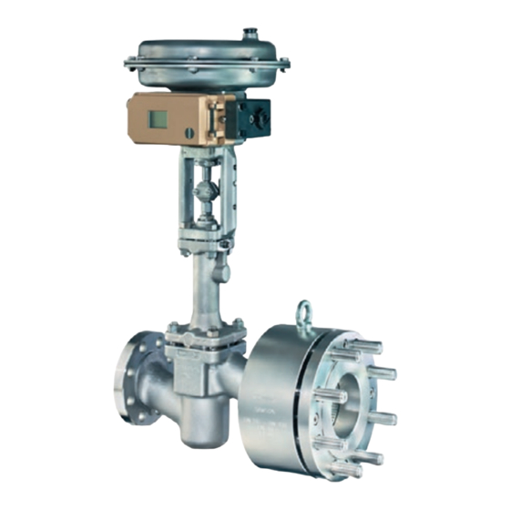
- Page 1 EB 8084 EN Translation of original instructions Series 3381 · Type 3381 Silencer DIN and ANSI versions Edition April 2021...
- Page 2 Note on these mounting and operating instructions These mounting and operating instructions assist you in mounting and operating the device safely. The instructions are binding for handling SAMSON devices. The images shown in these instructions are for illustration purposes only. The actual product may vary.
-
Page 3: Table Of Contents
Use of the Type 3381 Silencer together with self-operated regulators ....5-2 Preparation for installation ................5-4 Mounting the silencer ..................5-4 Testing the installed components ..............5-9 Start-up, operation, decommissioning, servicing ..........6-1 Removal ....................7-1 Removing the silencer from the pipeline ............7-1 Repairs ......................8-1 8.1 Returning devices to SAMSON ..............8-1 Disposal .....................9-1 Certificates ....................10-1 EB 8084 EN... - Page 4 Contents Annex......................11-1 11.1 Tightening torques, lubricants and tools ............11-1 11.2 After-sales service ..................11-1 EB 8084 EN...
-
Page 5: Safety Instructions And Measures
The silencer is designed to operate under exactly defined conditions (e.g. operating pressure, process medium, temperature). Therefore, operators must ensure that the silencer is only used in operating conditions that meet the specifications used for sizing at the ordering stage. In case operators intend to use the silencer in other applications or conditions than specified, contact SAMSON. SAMSON does not assume any liability for damage resulting from the failure to use the de- vice for its intended purpose or for damage caused by external forces or any other external factors. Î Refer to the technical data and nameplate for limits and fields of application as well as possible uses. - Page 6 − Safety harness when working at height − Safety footwear, ESD (electrostatic discharge) footwear, if necessary Î Check with the plant operator for details on further protective equipment. Revisions and other modifications Revisions, conversions or other modifications of the product are not authorized by SAMSON. They are performed at the user's own risk and may lead to safety hazards, for example. Fur- thermore, the product may no longer meet the requirements for its intended use. Safety features The Type 3381 Silencer does not have any special safety features.
- Page 7 − For oxygen service: Manual u H 01 The packaging of silencers constructed and sized for oxygen service has the following la- bel on it: Sauerstoff! Oxygen! Oxygène! − When a substance is used in the device, which is listed as being a substance of very high concern on the candidate list of the REACH regulation: Information on safe use of the part affected u www.samsongroup.com > About SAMSON > Material Compliance > REACH EB 8084 EN...
-
Page 8: Notes On Possible Severe Personal Injury
Safety instructions and measures If a device contains a substance which is listed as being a substance of very high concern on the candidate list of the REACH regulation, this circumstance is indicated on the SAMSON delivery note. 1.1 Notes on possible severe personal injury DANGER Risk of bursting in pressure equipment. Valves and pipelines are pressure equipment. Impermissible pressure or improper opening can lead to valve components bursting. -
Page 9: Notes On Possible Personal Injury
Safety instructions and measures 1.2 Notes on possible personal injury WARNING Risk of burn injuries due to hot or cold components and pipelines. Depending on the process medium, valve components and pipelines may get very hot or cold and cause burn injuries. Î... - Page 10 The lubricants to be used depend on the silencer material. Unsuitable lubricants may corrode and damage surfaces. Î Only use lubricants approved by SAMSON. Risk of the process medium being contaminated through the use of unsuitable lubri- cants and/or contaminated tools and components.
-
Page 11: Markings On The Device
Markings on the device 2 Markings on the device Item Inscription meaning 12 ID of the notified body 2.1 Nameplate PED: Pressure Equipment Directive G1/G2: gases and vapors Depending on the version, the Type 3381 Si- Fluid group 1 = hazardous Fluid group 2 = other lencer has a single or a two-piece name- L1: liquids plate: Fluid group 1 = hazardous Fluid group 2 = other I/II/III: Category 1 to 3 13 Serial number Fig. 2-1: Single nameplate on the valve... - Page 12 EB 8084 EN...
-
Page 13: Design And Principle Of Operation
Design and principle of operation 3 Design and principle of oper- Type 3381-R: ation − Reduced construction using less material: single attenuation plates with reduced di- ameter and possibly reduced thickness, 3.1 Design clamped between the valve or a pipe ex- pander and the pipe flange (see Type 3381-1: Fig. 3-2). − Single attenuation plates mounted be- Type 3381-3-X: tween the valve or a pipe expander and the pipe flange (see Fig. 3-1). - Page 14 Design and principle of operation − A graphite gasket with metal core Note (1.4301) is used in the standard version Additional installation examples of various as a seal between the housing and versions can be found in the Data Sheet clamping flange.
-
Page 15: Principle Of Operation
3.2 Principle of operation 3.3 Technical data The Type 3381 Silencer provides noise atten- Noise emissions uation by acting as a fixed restriction. The si- SAMSON is unable to make general state- lencer raises the pressure of the medium flow ments about noise emissions. The noise emis- at the valve outlet and reduces the pressure sions depend on the valve version, plant fa- downstream of the silencer to the required cilities and process medium. - Page 16 Design and principle of operation Table 3-2: Possible wafer‑type versions for Type 3381‑1R as well as for combinations of Type 3381‑1 and Type 3381‑1R Note: − Wafer-type version only for standard materials according to Table 3-1 − Only nominal sizes possible according to the standard and depending on the pressure rating DIN EN versions ANSI versions Nominal size Pressure rating (min.) Nominal size...
-
Page 17: Shipment And On-Site Transport
Î Only use approved lifting equipment and damage. Report any damage to accessories whose minimum lifting ca- SAMSON and the forwarding agent pacity is higher than the weight of the si- (refer to delivery note). lencer (including the packaging, if appli- 3. -
Page 18: Transporting The Silencer
Shipment and on-site transport 4.3.1 Transporting the silencer WARNING Risk of injury due to incorrect lifting without The silencer can be transported using lifting the use of lifting equipment. equipment (e.g. crane or forklift). Lifting the silencer without the use of lifting Î... -
Page 19: Lifting The Silencer
Shipment and on-site transport 4.3.2 Lifting the silencer the pipeline flange (see the 'Installation' section). To install a large silencer into the pipeline, 5. After installation in the pipeline, check use lifting equipment (e.g. crane or forklift) whether the flanges are bolted tight or to lift it. the welding joints hold and the valve in- Lifting instructions cluding the silencer in the pipeline holds. - Page 20 Shipment and on-site transport b) Type 3381-3-X with valve eyelet of the actuator and to the rigging equipment of the crane or forklift. See Fig. 4-2 NOTICE! This sling must not bear any load. It only protects it from tilting while NOTICE being lifted. Before lifting the control Incorrect lifting will damage the valve.
- Page 21 Shipment and on-site transport Mid-axis Fig. 4-2: Type 3381‑3‑X with valve EB 8084 EN...
-
Page 22: Storing The Silencer
SAMSON's After‑sales Service can provide Î Observe the storage instructions. more detailed storage instructions on re- Î Avoid long storage times. quest. Î Contact SAMSON in case of different storage conditions or longer storage times. Note We recommend regularly checking the si- lencer and the prevailing storage conditions during long storage periods. -
Page 23: Installation
Installation 5 Installation The Type 3381-3-X Silencer is bolted to the control valve using a suitable gasket before The work described in this section is only to they are both installed into the pipeline using be performed by personnel appropriately suitable gaskets. qualified to carry out such tasks. Type 3381-4-X The following documents are also required Two to five attenuation plates are clamped for mounting the silencer: between the valve outlet or pipe expander... -
Page 24: Use Of The Type 3381 Silencer Together With Self-Operated Regulators
Installation 5.1.3 Use of the Type 3381 Si- Fig. 5-1 to Fig. 5-4 show the resulting instal- lation situations. lencer together with self-operated regulators Excess pressure valves Excess pressure valves regulate the upstream pressure. Therefore, the excess pressure valve can be installed and the control lines connected as normal. Pressure reducing valves and differential pressure regulators If a Type 3381 Silencer is installed down- stream of a pressure reducing valve or differ- ential pressure regulator, the control lines cannot be connected to the pipeline up- stream of the silencer. - Page 25 Installation 6xDN 6xDN Fig. 5-2: Differential pressure regulator (open- Fig. 5-1: Pressure reducing valve ing) 6xDN To flow pipe To return flow pipe Fig. 5-3: Differential pressure regulator (closing) Fig. 5-4: Differential pressure regulator (closing) in the flow pipe in the return flow pipe EB 8084 EN...
-
Page 26: Preparation For Installation
Installation 5.2 Preparation for installation 5.3 Mounting the silencer Before installation, make sure the following NOTICE conditions are met: Risk of damage to components due to work − Valve and silencer are clean. being carried out by personnel not quali- − The valve and silencer data (type desig- fied for such tasks. - Page 27 Installation 1. Close the shut-off valves in the pipeline Flange Flange Attenuation at the inlet and outlet of the plant section Valve outlet Pipeline plate while the valve is being installed. 2. Prepare the relevant section of the pipe- line for installing the components. 3. Remove any protective caps before in- stalling the components.
- Page 28 Installation remove the studs inserted in the delivered state. To proceed, lock the nut on the stud with another nut. Use this nut to loosen the stud. Unthread the stud. Bolting the valve and silencer together See Fig. 5-7 to Fig. 5-9 1. Lift the silencer using suitable lifting equipment onto the valve (see informa- tion under 'Lifting the silencer' in the 'Shipment and on-site transport' section).
- Page 29 Installation lencer is always in the horizontal posi- tion and that the axis of the plug/actua- tor stem remains in the vertical position during lifting. 1. Close the shut-off valves in the pipeline at the inlet and outlet of the plant section while the valve is being installed. 2. Prepare the relevant section of the pipe- line for installing the valve and silencer. 3.
- Page 30 Installation Fig. 5-11: Position valve and silencer properly before lifting Fig. 5-13: Valve and silencer in the pipeline, ready to be bolted Mid-axis Fig. 5-12: Lifting Fig. 5-14: Valve and silencer in the pipeline EB 8084 EN...
-
Page 31: Testing The Installed Components
Installation Note Studs and nuts: number of studs and nuts varies depending on the number of holes in the valve's inlet flange and the silencer's out- let flange. Fig. 5-15: Valve and silencer installed in the pipeline 5.4 Testing the installed com- ponents See associated control valve documentation for the tests to be performed before start-up. - Page 32 5-10 EB 8084 EN...
-
Page 33: Start-Up, Operation, Decommissioning, Servicing
Start-up, operation, decommissioning, servicing 6 Start-up, operation, decom- missioning, servicing Details on start-up, decommissioning, opera- tion and servicing are described in the asso- ciated valve documentation. EB 8084 EN... - Page 34 EB 8084 EN...
-
Page 35: Removal
Removal 7 Removal 7.1 Removing the silencer from the pipeline The work described in this section is only to be performed by personnel appropriately a) Version with flanges qualified to carry out such tasks. 1. Support the silencer to hold it in place WARNING when separated from the pipeline (see Risk of burn injuries due to hot or cold com- the 'Shipment and on-site transport' sec- ponents and pipeline. - Page 36 EB 8084 EN...
-
Page 37: Repairs
Î Do not perform any repair work on your ments are clearly visible. own. 4. Send the shipment to the address given Î Contact SAMSON's After‑sales Service on the RMA. for repair work. Note 8.1 Returning devices to... - Page 38 EB 8084 EN...
-
Page 39: Disposal
Disposal 9 Disposal Î Observe local, national and internation- al refuse regulations. Î Do not dispose of components, lubricants and hazardous substances together with your household waste. EB 8084 EN... - Page 40 EB 8084 EN...
-
Page 41: Certificates
Certificates 10 Certificates The declaration is provided on the next page: − Declaration of conformity in compliance with Pressure Equipment Directive 2014/68/EU The certificate shown was up to date at the time of publishing. Other optional or updat- ed certificates are available on request. EB 8084 EN 10-1... - Page 42 10-2 EB 8084 EN...
- Page 43 − Is a strainer installed? E-mail address − Installation drawing You can reach our after-sales service at aftersalesservice@samsongroup.com. Addresses of SAMSON AG and its subsid- iaries The addresses of SAMSON AG, its subsid- iaries, representatives and service facilities worldwide can be found on our website (www.samsongroup.com) or in all SAMSON product catalogs.
- Page 44 11-2 EB 8084 EN...
- Page 48 EB 8084 EN SAMSON AKTIENGESELLSCHAFT Weismüllerstraße 3 · 60314 Frankfurt am Main, Germany Phone: +49 69 4009-0 · Fax: +49 69 4009-1507 samson@samsongroup.com · www.samsongroup.com...
Need help?
Do you have a question about the 3381 Series and is the answer not in the manual?
Questions and answers