Samson 3374 Mounting And Operating Instructions
Electric actuator
Hide thumbs
Also See for 3374:
- Mounting and operating instructions (134 pages) ,
- Mounting and operation instructions (68 pages) ,
- Mounting and operating instructions (16 pages)

Related Manuals for Samson 3374


Summary of Contents for Samson 3374
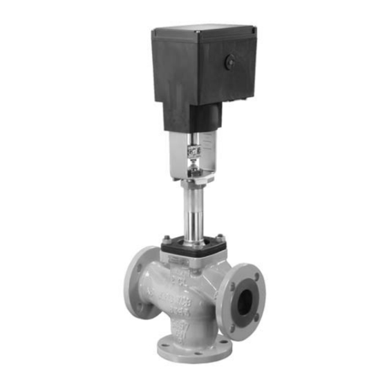
- Page 1 Electric Actuator Type 3374 Fig. 1 ⋅ Type 3374 Actuator mounted on Type 3535 Three-way Valve Mounting and Operating Instructions EB 8331-1 EN Edition March 2004...
-
Page 2: Table Of Contents
Contents Safety instructions Contents Page Design and principle of operation ..... . 3 Additional equipment ......3 Technical data . -
Page 3: Design And Principle Of Operation
Design and principle of operation 1 Design and principle of operation 1.1 Additional equipment The Type 3374 Electric Actuator is used in The actuators can be equipped with addi- industrial plants as well as in heating, venti- tional units, such as limit switches and poten- lation and air-conditioning systems. -
Page 4: Technical Data
Technical data 1.2 Technical data Actuator Type 3374 Version with Yoke Ring nut Yoke Ring nut Yoke Ring nut Fail-safe action Without Actuator stem extends Actuator stem retracts Rated travel 30/15 Actuating time 240/120 for rated travel Actuating time –... - Page 5 Maximum two current inputs may be switched in series Maximum values ±50 mA or ±25 V SAMSON TROVIS-VIEW Configuration and Operator Interface software, SAMSON memory pen Can only be taken from current or voltage signal Not when retrofittable interface is used...
-
Page 6: Installation
Installation 4. When the coupling nut (8) fits closely 2 Installation onto the actuator stem, attach both coupling clamps (4) and screw tight. 2.1 Mounting position 5. Move actuator stem (3) to the end posi- Installation depends on the mounting posi- tion (valve closed) using the manual tion of the valve. - Page 7 Installation Attachment to Series V 2001, Type 3260 DN 65 to 150 and Attachment to Series 240 Type 3214 DN 65 to 100 Actuator 2.1 Actuator yoke 2.2 Valve yoke 2.3 Bonnet Actuator stem Stem connector Plug stem Ring nut Coupling nut Attachment to Type 3214 Lock nut...
-
Page 8: Electrical Connections
Electrical connections 3 Electrical connections Install electrical connections as indicated on Upon installation of the electric con- the circuit diagram included in the actuator nections, you are required to ob- cover and as illustrated in Figs. 3 and 4. serve the regulations concerning A maximum of 3 cable glands can be at- electrical power plant systems ac- tached to the housing for cable entries. - Page 9 Electrical connections Warning! Only connect to the main power network Particularly for 24 V, 50 Hz actuators, when the power is switched off. use wires with a sufficiently large cross- section to guarantee that the permissible Only use power interruption devices voltage tolerances are not exceeded.
-
Page 10: Operation And Adjustment
Operation and adjustment 4 Operation and adjustment 4.2.2 Potentiometers The gears of the potentiometers (12) and 4.1 Manual operation of the actua- (13) must be put onto their shafts corre- sponding with the rated travel of the control valve. The rated travel inscription “Nenn- To operate the manual override, place hub 15“... - Page 11 Operation and adjustment Limit switch Stem retracts Metal tag Stem extends Rated travel inscription 12.1 13.1 Microswitch Spindle upwards Spindle downwards Intermediate gear Cam bracket Gear potentiometer 1 12.1 Potentiometer shaft Gear potentiometer 2 13.1 Potentiometer shaft Fig. 5 ⋅ Adjustment EB 8331-1 EN...
-
Page 12: Setting The Digital Positioner
"extends" are only de- Setup with operating modes 3 and 0 = signed for a rated travel of 15 mm. Do not can only be performed using a SAMSON rearrange the gear! memory pen as storage medium, or in con- nection with SAMSON’s TROVIS-VIEW... - Page 13 Calibrate the travel either on the test tracting actuator stem. bench or when the shut-off valves in the plant are closed. Operating mode 1 SAMSON Selector switch Operating mode 2 Travel calibration button Operating mode 0 Operating mode 3...
- Page 14 Setting the digital positioner After pressing the calibration button (4), the Do not adjust the potentiometer before the actuator stem first extends to the closing po- closing position is actually reached. This is sition of the valve as far as it will go. Cali- indicated by the associated, activated limit bration is concluded when both signal switch on the board (Fig.
-
Page 15: Retrofitting Additional Electrical Equipment
As a result, travel calibration via the poten- The actuator version is marked on the name- tiometer gear with rated travel 15 or 30 is plate, e.g. Model 3374-11000002000. limited to 6 mm. Each pressing of the button further increases When ordering additional electrical equip- the travel range by 1 mm. -
Page 16: Limit Switches
Limit switches 6. Push adjustment gears (8) onto their 5.1 Limit switches spindles and fasten with one screw The retrofit kit (order no. 1400-8830) is re- each. quired to install limit switches. If the actua- Check whether the adjustment screws tor is not already equipped with poten- can be turned easily. - Page 17 7.1 Position of the contact cams (6) on the cam bracket (7) For actuator stem extends retracts 7.2 Position of the cam bracket (7) For actuator stem extends For actuator stem retracts Fig. 7 ⋅ Retrofitting limit switches, here for model 3374-11000002000, version with potentiometers EB 8331-1 EN...
-
Page 18: Potentiometers
Potentiometers 2. Clip the spindle gear (2) onto the 5.2 Potentiometers sleeve (3) as illustrated in Fig. 7, top. Actuators with a digital positioner cannot Make sure the lateral latch is properly be equipped with potentiometers! engaged in the groove of the sleeve. To retrofit the potentiometers, an actuator 3. -
Page 19: Digital Positioner
Make sure that the gears are An appropriate actuator board, TROVIS- properly engaged. Fasten the board VIEW software for 3374 as well as a con- using screws. necting cable (order no. 0450-1978) are re- 6. To calibrate the positioner, proceed as quired to retrofit the digital positioner. -
Page 20: Dimensions In Mm
Dimensions in mm 6 Dimensions in mm Version with yoke Version with ring nut Stem connector EB 8331-1 EN... - Page 21 EB 8331-1 EN...
- Page 22 SAMSON AG ⋅ MESS- UND REGELTECHNIK Weismüllerstraße 3 ⋅ 60314 Frankfurt am Main ⋅ Germany Phone: +49 69 4009-0 ⋅ Fax: +49 69 4009-1507 EB 8331-1 EN Internet: http://www.samson.de...
Need help?
Do you have a question about the 3374 and is the answer not in the manual?
Questions and answers