Samson 3374 Mounting And Operation Instructions
Electric actuator
Hide thumbs
Also See for 3374:
- Mounting and operating instructions (134 pages) ,
- Mounting and operating instructions (60 pages) ,
- Mounting and operating instructions (92 pages)

Related Manuals for Samson 3374


Summary of Contents for Samson 3374
- Page 1 EB 8331-3 EN Translation of original instructions Type 3374 Electric Actuator Three-step version Edition January 2023...
- Page 2 Note on these mounting and operating instructions These mounting and operating instructions assist you in mounting and operating the device safely. The instructions are binding for handling SAMSON devices. The images shown in these instructions are for illustration purposes only. The actual product may vary.
-
Page 3: Table Of Contents
Contents Safety instructions and measures ..............1-1 Notes on possible severe personal injury ............1-4 Notes on possible personal injury ..............1-5 Notes on possible property damage .............1-6 Markings on the device ................2-1 Nameplate ....................2-1 Design and principle of operation ...............3-1 Fail-safe action ...................3-1 Versions .....................3-1 Additional equipment ..................3-2 Technical data ....................3-3... - Page 4 Decommissioning ..................10-1 Removal ....................11-1 11.1 Construction with integrated yoke ...............11-1 11.2 Construction with ring nut ................11-2 Repairs ....................12-1 12.1 Returning the actuator to SAMSON ............12-1 Disposal ....................13-1 Certificates ....................14-1 14.1 Information on the UK sales region .............14-1 Annex......................15-1 15.1 Parts for retrofitting and accessories ............15-1 15.2...
-
Page 5: Safety Instructions And Measures
Therefore, operators must ensure that the actuator is only used in operating conditions that meet the specifications used for sizing the actuator at the ordering stage. In case operators intend to use the actuator in applications or conditions other than those specified, contact SAMSON. SAMSON does not assume any liability for damage resulting from the failure to use the de- vice for its intended purpose or for damage caused by external forces or any other external factors. Î Refer to the technical data for limits and fields of application as well as possible uses. See the 'Design and principle of operation' section. - Page 6 Revisions and other modifications Revisions, conversions or other modifications of the product are not authorized by SAMSON. They are performed at the user's own risk and may lead to safety hazards, for example. Fur- thermore, the product may no longer meet the requirements for its intended use. Safety features Upon supply voltage failure, the Type 3374 Electric Actuator causes the valve to move to a certain fail-safe position. The fail-safe action of SAMSON actuators is specified on the actua- tor nameplate. Type 3374-21/-26/-31/-36...
- Page 7 Referenced standards, directives and regulations Devices with a CE marking fulfill the requirements of the following Directives: − 2014/30/EU − 2014/35/EU − 2011/65/EU Devices with a UKCA marking fulfill the requirements of the following Regulations: − SI 2016 No. 1091 (The Electromagnetic Compatibility Regulations 2016) − SI 2016 No. 1101 (The Electrical Equipment (Safety) Regulations 2016) − SI 2012 No. 3032 (The Restriction of the Use of Hazardous Substances in Electrical and Electronic Equipment Regulations 2012) Devices with an EAC marking fulfill the requirements of the following Regulations: − TR CU 004/2011 − TR CU 020/2011 The 'Certificates' section contains these declarations of conformity and TR CU certificate. The Type 3374 Electric Actuator is designed for use in low-voltage installations. Î For wiring, maintenance and repair, observe the relevant safety regulations. EB 8331-3 EN...
-
Page 8: Notes On Possible Severe Personal Injury
Safety instructions and measures Referenced documentation The following documents apply in addition to these mounting and operating instructions: − Mounting and operating instructions of the valve on which the electric actuator is mount- ed, e.g. for SAMSON valves: u EB 5861 for Type 3260 Three-way Valve u EB 5868 for Type 3213 and Type 3214 Globe Valves u EB 8012 for Type 3241 Globe Valve, ANSI and JIS version u EB 8015 for Type 3241 Globe Valve, DIN version... -
Page 9: Notes On Possible Personal Injury
Safety instructions and measures 1.2 Notes on possible personal injury WARNING Crush hazard arising from moving parts. The electric actuator contains moving parts (actuator and plug stems), which can injure hands or fingers if inserted into the actuator. Î Do not insert hands or finger into the yoke while the valve is in operation. Î Disconnect the supply voltage and protect it against unintentional reconnection be- fore performing any work on the control valve. -
Page 10: Notes On Possible Property Damage
NOTICE Risk of damage to the electric actuator due to the supply voltage exceeding the per- missible tolerances. The Type 3374 Electric Actuator is designed for use according to regulations for low-voltage installations. Î Observe the permissible tolerances of the supply voltage. Risk of actuator damage due to excessively high tightening torques. -
Page 11: Markings On The Device
2 Markings on the device 2.1 Nameplate The nameplate shown was up to date at the time of publication of this document. The name- plate on the device may differ from the one shown. 3374-21 000000000.00 *123456789* 09/2022 2500 N... - Page 12 EB 8331-3 EN...
-
Page 13: Design And Principle Of Operation
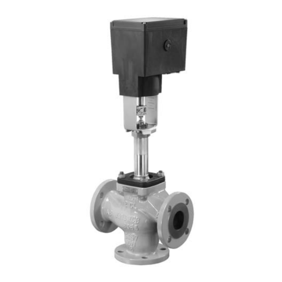
Fig. 3-1: Construction with integrated yoke (form B) The Type 3374 Electric Actuator is available with or without fail-safe action. Type 3374-2x and Type 3374-3x Actuators are able to perform a fail-safe action and contain a spring assembly and an electro- magnet. The actuator is moved by the force of the spring to the fail-safe position when the electromagnet is de-energized. -
Page 14: Additional Equipment
Design and principle of operation 3.3 Additional equipment The actuator can be equipped with mechani- cal limit contacts or with resistance transmit- ters to influence the tasks of control equip- ment. Mechanical limit contacts Optionally, the actuator can be equipped with two limit contacts. They consist of two changeover switches. -
Page 15: Technical Data
Design and principle of operation 3.4 Technical data Table 3-1: Technical data · Type 3374 Type 3374 Ring Ring Version with Yoke Ring nut Yoke Yoke Fail-safe action Without Extends Retracts Rated travel Stroking speed Standard mm/s 0.125 0.125 Fast mm/s 0.25... - Page 16 Design and principle of operation Type 3374 Permissible temperature ranges 2) Temperature Ambient 5 to 60 °C ranges 2) Storage –25 to +70 °C Materials Housing and cover: Plastic (glass-fiber reinforced PPO) Weight kg (approx.) Safety Degree of protection IP 54 acc. to EN 60529, (IP 65 with three cable glands Suspended mounting position not approved Class of protection II according to EN 61140 Device safety According to EN 61010-1 Noise immunity According to EN 61000-6-2 and EN 61326-1...
-
Page 17: Dimensions
Type 3374 Dimension h Dimension h ≥60 Fig. 3-3: Dimensions in mm · Type 3374, version with integrated yoke (form B) Note The dimension h indicates the minimum clearance required to be able to operate the actuator. Sufficient clearance must be available to facilitate wiring and operation. We recommend a minimum clearance of 600 mm. - Page 18 Dimension h Dimension h Dimension h ≥100 Fig. 3-4: Dimensions in mm · Type 3374, version with ring nut (form A) Note The dimension h indicates the minimum clearance required to be able to operate the actua- tor. We recommend an even greater clearance of at least 600 mm to facilitate wiring and operation.
-
Page 19: Shipment And On-Site Transport
M30x1.5 ring nut 2. Check the shipment for transportation Fig. 4-1: Scope of delivery damage. Report any damage to SAMSON and the forwarding agent (refer to delivery note). 4.3 Transporting the actuator 4.2 Removing the packaging − Protect the actuator against external in- fluences (e.g. impact). -
Page 20: Storing The Actuator
NOTICE Risk of electric actuator damage due to improper storage. Î Observe the storage instructions. Î Avoid long storage times. Î Contact SAMSON in case of different storage conditions or longer storage times. Note We recommend regularly checking the elec- tric actuator and the prevailing storage con- ditions during long storage periods. -
Page 21: Installation
Installation 5 Installation The work described in this section is only to be performed by personnel appropriately quali- fied to carry out such tasks. 5.1 Installation conditions Work position If not described otherwise in the valve documentation, the work position for the control valve is the front view looking onto the operating controls. Mounting orientation The control valve can be installed in the pipeline in any desired position. However, a sus- pended mounting position of the actuator is not permissible (see Fig. 5-1). -
Page 22: Preparation For Installation
− Series V2001 Valves (DN 15 to 80) − Type 3260 (DN 65 to 80) Tightening torque 100 Nm − Type 3260 (DN 100 to 150, only with 4. When the plug stem (5) fits closely onto Type 3374-10) the actuator stem (3), attach both stem − Type 3214 (DN 65 to 100) connector clamps (4) and fasten with Î See Fig. 5-3. screws. 1. Remove protective covers and unscrew nut (6) from the valve. - Page 23 Installation Attachment − Series V2001 Valves (DN 65 to 100) Types 3374-10/-11/-21/-31 (depending on valve travel) Î See Fig. 5-4. Connection with yoke (form B) Attachment to Series V2001 Valves, Note Type 3260 (DN 65 to 150), Type 3214 (DN 65 to 100) The V2001 mounting kit (see Annex) is re- quired for mounting the actuator on Series V2001 (DN 65 to 100).
- Page 24 Installation Types 3374-10/-11/-21/-31 Connection with yoke (form B) Attachment to Series V2001 Valves (DN 65 to 100) Fig. 5-5: Mounting kit V2001 5.3.2 Construction with ring nut (form A) Attachment to Series 240 Valves Î See Fig. 5-7. 1. Push the plug stem (5) down to close the valve. 2. Turn the stem connector nut (8) until the dimension x = 75 mm (DN 100 and...
- Page 25 Installation Types 3374-15/-17/-26/-36 Connection with ring nut (form A) Attachment to Series 240 Valves Actuating shaft Fig. 5-6: Actuating shaft for manual override (actuator for attachment with ring nut) Note For actuators with "actuator stem extends" fail-safe action, the supply voltage must be applied to allow the actuator stem be retract- ed.
- Page 26 5. Align travel indicator scale (10) with the 1. Retract actuator stem (3) as described in middle of the stem connector (4) and the 'Operation' section (see Fig. 5-8 and screw tight. Fig. 5-9). Type 3374-15 Connection with ring nut (form A) Attachment to Type 3214 Valve (DN 125 to 250) Actuating shaft Fig. 5-8: Actuating shaft for manual override...
-
Page 27: Installing The Control Valve Into The Pipeline
Installation 5.4 Installing the control valve into the pipeline We recommend applying a small amount of lubricant (e.g. Vaseline) to the spindles on Î Install the valve into the pipeline accord- the gear faces and to the sides of the cogs. ing the specifications in the mounting and operating instructions of the valve. - Page 28 Installation Intermediate gear Spindle gear Serrated ring (for 1) Tension spring Serrated ring (for 10) 10 Shim Fig. 5-10: Basic unit Serrated ring Spacer Retaining ring 16 Screw WN 1412 17 Terminal board 18 Adjustment gear 19 Contact cam 20 Cam holder Fig. 5-11: Mechanical limit contacts EB 8331-3 EN...
- Page 29 Installation Actuators without resistance transmitters corresponding with the position of the actuator stem. 1. Unscrew screws on housing cover and take the cover off the actuator. 11. Slide the cam holder (20) with both con- tact cams (19) onto the spindle 2 (11.2) 2. Move the actuator stem to the end position corresponding with the position of the depending on the fail-safe action "actua- actuator stem as illustrated in Fig. 5-14.
- Page 30 Installation 11.1 11.2 Intermediate gear Actuator board Spindle gear Bearing sleeve Serrated ring Terminal board Tension spring Adjustment gear Spacer Contact cam 11.1 Spindle 1 Cam holder 11.2 Spindle 2 Fig. 5-12: Inside view · Actuator without resistance transmitters 5-10 EB 8331-3 EN...
- Page 31 Installation When actuator stem retracted Actuator stem re- Actuator stem tracted extended Fig. 5-13: Contact cams and cam holder Intermediate gear Adjustment gear Contact cam When actuator stem extended Cam holder Fig. 5-14: Contact cam unit Contact cam Actuators with resistance transmitters 3. Remove serrated ring (6) and shim (10) from spindle 2 (11.2). See Fig. 5-15.
- Page 32 Installation 11.2 Serrated ring Shim 11.2 Spindle 2 Actuator board Fig. 5-15: Inside view · Actuator with resistance transmitters 5-12 EB 8331-3 EN...
-
Page 33: Installing The Resistance Transmitters
Installation 5.5.2 Installing the resistance gaged in the groove of the sleeve. Slide the intermediate gear (1) onto the spin- transmitters dle 1 (11.1), mount the serrated ring (3) An actuator board with the corresponding and push it down as far as it will go. resistance transmitters and gear wheels is re- 3. - Page 34 Installation 22.1 23.1 Gear for potentiometer 1 Gear for potentiometer 2 22.1 Axis of potentiometer 1 23.1 Axis of potentiometer 2 Fig. 5-16: Gears with retaining rings 5-14 EB 8331-3 EN...
- Page 35 Installation 11.1 11.2 11.4 11.3 Intermediate gear 11.1 Spindle 1 Spindle gear 11.2 Spindle 2 Serrated ring 11.3 Spindle 3 Tension spring 11.4 Spindle 4 Serrated ring Actuator board Shim Fig. 5-17: Inside view · Actuator without limit contacts EB 8331-3 EN 5-15...
- Page 36 Installation Actuators with limit contacts 4. Slide new actuator board into its guid- ing. Make sure that the gears are prop- 1. Unscrew screws on housing cover and erly engaged. Fasten the board using take the cover off the actuator. screws.
-
Page 37: Electrical Connection
Installation 5.6 Electrical connection DANGER Risk of fatal injury due to electric shock. Î Upon installation of the electric cables, you are required to observe the regula- tions concerning low-voltage installations according to DIN VDE 0100 as well as the regulations of your local power sup- plier. - Page 38 Installation Mechanical limit contacts 41 44 42 51 54 Controller – Resistance transmitters Type 3374 Actuator Version with fail-safe action only Fig. 5-19: Electrical connection Table 5-1: Cables and stranded wires that can be used Cable Cross section Single-wire H05(07) V-U 0.2 to 1.5 mm² Fine-wire H05(07) V-K 0.2 to 1.5 mm² With wire ferrule acc. to DIN 46228-1 0.25 to 1.5 mm²...
-
Page 39: Start-Up
Start-up 6 Start-up 3. Use the motor or manual override to move the actuator stem to the point at Once the actuator has been mounted cor- which the contact should react. rectly and the wiring has been performed as 4. Use the 4 mm hex wrench to turn spindle described in the 'Installation' section, the of the adjustment gears (18) for the up- electric actuator is ready for use and can be... -
Page 40: Adjusting The Resistance Transmitter
Start-up 6.2 Adjusting the resistance Zero adjustment transmitter 1. Use the motor or manual override to move the valve to the desired end posi- The gears of the resistance transmitters (22) tion. and (23) must be put onto their shafts to cor- 2. -
Page 41: Operation
Operation 7 Operation 7.2 Mechanical override After connecting the supply voltage, the ac- To operate the manual override, place a tuator is ready for use. 4 mm hex wrench on the red actuator shaft located at the side of the housing (see 7.1 Three-step mode Fig. 7-2). Turn the hex wrench clockwise to move the actuator in 'aL' direction and In three-step mode, the actuator stem is counterclockwise to move it in the 'eL' moved in the corresponding direction by ap-... - Page 42 EB 8331-3 EN...
-
Page 43: Malfunctions
Malfunctions 8 Malfunctions Î Troubleshooting (see Table 8-1). Note Contact SAMSON's After-sales Service for malfunctions not listed in the table. Table 8-1: Troubleshooting Error Possible reasons Recommended action Î Check attachment. Actuator stem does not move. Actuator is blocked. Î Remove the blockage. - Page 44 EB 8331-3 EN...
-
Page 45: Servicing
Note The electric actuator was checked by SAMSON before it left the factory. − The product warranty becomes void if service or repair work not described in these instructions is performed without prior agreement by SAMSON's After-sales Service. - Page 46 EB 8331-3 EN...
-
Page 47: Decommissioning
Decommissioning 10 Decommissioning To decommission the electric actuator for re- pair work or disassembly, proceed as fol- The work described in this section is only to lows: be performed by personnel appropriately Î Put the control valve out of operation. qualified to carry out such tasks. - Page 48 10-2 EB 8331-3 EN...
-
Page 49: Removal
Removal 11 Removal 11.1 Construction with inte- grated yoke The work described in this section is only to be performed by personnel appropriately Actuator without fail-safe action qualified to carry out such tasks. 1. Disconnect the supply voltage and pro- tect it against unintentional reconnection. DANGER 2. -
Page 50: Construction With Ring Nut
Removal Î The actuator stem moves to the fail-safe 4. Remove the connecting lines. position. 5. Retract actuator stem as described in the 7. Disconnect the wires of the connecting 'Operation' section. lines. 6. Undo the stem connector parts between 8. - Page 51 Removal Î The actuator stem moves to the fail-safe position. 2. Make sure that a signal from the control- ler cannot act upon the actuator. If neces- sary, disconnect the wires connecting the controller. 3. Disconnect the wires of the connecting lines at the actuator.
- Page 52 Removal 11-4 EB 8331-3 EN...
-
Page 53: Repairs
Risk of actuator damage due to incorrect service or repair work. Î Do not perform any repair work on your own. Î Contact SAMSON's After-sales Service for repair work. 12.1 Returning the actuator to SAMSON Defective actuators can be returned to SAMSON for repair. - Page 54 12-2 EB 8331-3 EN...
-
Page 55: Disposal
Disposal 13 Disposal SAMSON is a producer registered at the following European institution u https://www.ewrn.org/ national-registers/national- registers. WEEE reg. no.: DE 62194439/FR 025665 Î Observe local, national and internation- al refuse regulations. Î Do not dispose of components, lubricants and hazardous substances together with your other household waste. - Page 56 13-2 EB 8331-3 EN...
-
Page 57: Certificates
14.1 Information on the UK sales region The following information corresponds to the Pressure Equipment (Safety) Regulations 2016, STATUTORY INSTRUMENTS, 2016 No. 1105 (UKCA marking). It does not apply to Northern Ireland. Importer SAMSON Controls Ltd Perrywood Business Park Honeycrock Lane Redhill, Surrey RH1 5JQ Phone: +44 1737 766391 E-mail: u sales-uk@samsongroup.com Website: u uk.samsongroup.com EB 8331-3 EN... - Page 58 Certificates EU declaration of conformity 14-2 EB 8331-3 EN...
- Page 59 Signed for and behalf of the manufacturer: Fabio Roma Sebastian Krause Vice President Smart Products & Components Director Development Valves & Actuators Revision 00 Classification: Public · SAMSON AKTIENGESELLSCHAFT · Weismuellerstrasse 3 · 60314 Frankfurt am Main, Germany Page 1 of 1 EB 8331-3 EN 14-3...
- Page 60 Certificates TR CU certificate 14-4 EB 8331-3 EN...
- Page 61 Certificates EB 8331-3 EN 14-5...
- Page 62 Certificates Declaration of incorporation 14-6 EB 8331-3 EN...
-
Page 63: Annex
Order no. 1400-9515 Spacer to mount the actuator on Type 3323 Valve (DN 65 to 80) Order no. 0340-3031 Set with three cable glands M20x1.5 with metal nut (SW 23/24) Order no. 1400-8828 Table 15-1: Resistance transmitters · Selecting the actuator board 1) Type 3374 Standard Order no. 1180-9601 Order no. 1180-9607 230 V/50 Hz Faster motor Order no. 1180-9604 –... -
Page 64: After-Sales Service
E-mail contact You can reach our after-sales service at aftersalesservice@samsongroup.com. Addresses of SAMSON AG and its subsid- iaries The addresses of SAMSON, its subsidiaries, representatives and service facilities worldwide can be found on our website (u www.samsongroup.com) or in all... - Page 68 EB 8331-3 EN SAMSON AKTIENGESELLSCHAFT Weismüllerstraße 3 · 60314 Frankfurt am Main, Germany Phone: +49 69 4009-0 · Fax: +49 69 4009-1507 samson@samsongroup.com · www.samsongroup.com...
Need help?
Do you have a question about the 3374 and is the answer not in the manual?
Questions and answers