Samson 3374 Mounting And Operating Instructions
Electric actuator
Hide thumbs
Also See for 3374:
- Mounting and operating instructions (134 pages) ,
- Mounting and operation instructions (68 pages) ,
- Mounting and operating instructions (60 pages)
Table of Contents

Subscribe to Our Youtube Channel
Related Manuals for Samson 3374


Summary of Contents for Samson 3374
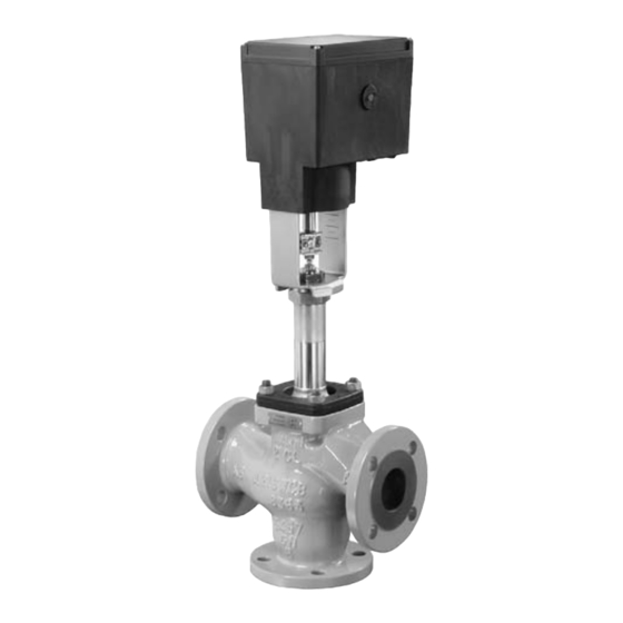
- Page 1 Electric Actuator Type 3374 Fig. 1 · Type 3374 Actuator mounted on a Type 3535 Three-way Valve Mounting and Operating Instructions EB 8331-1 EN Edition October 2007 Download from Www.Somanuals.com. All Manuals Search And Download.
-
Page 2: Table Of Contents
Contents Contents Page Design and principle of operation ....5 Additional equipment......5 Technical data . - Page 3 Safety instructions General safety instructions Assembly, start-up and operation of this device may only be performed by trained and experienced personnel familiar with the product. According to these mounting and operating instructions, trained personnel refers to individuals who are able to judge the work they are assigned to and recognize possible hazards due to their specialized training, their knowledge and experience as well as their knowledge of the applicable standards.
- Page 4 Note: Actuators with a CE marking fulfill the requirements of the Directives 94/9/EC and 89/336/EEC. The Declaration of Conformity is available on request. EB 8331-1 EN Download from Www.Somanuals.com. All Manuals Search And Download.
-
Page 5: Design And Principle Of Operation
The actuators can be equipped with addi- tional units, such as limit switches and po- The Type 3374 Electric Actuator is used in tentiometers, to influence the tasks of control industrial plants as well as in heating, venti- equipment. In addition, the actuator can be lation and air-conditioning systems. -
Page 6: Technical Data
Design and principle of operation Technical data Actuator Type 3374 Version with Yoke Ring nut Yoke Ring nut Yoke Ring nut Safety function Without Stem extends Stem retracts Rated travel 30/15 Actuating time for 240/120 rated travel Actuating time in case of –... - Page 7 Maximum two current inputs may be switched in series Maximum values ±50 mA or ±25 V SAMSON TROVIS-VIEW Operator Interface software, SAMSON memory pen Can only be taken from current or voltage signal Not when retrofittable interface is used EB 8331-1 EN Download from Www.Somanuals.com.
-
Page 8: Installation
Installation Installation the top of the coupling nut (8) is reached. Secure position with lock nut Mounting position (9). 3. Place actuator onto valve bonnet (2.3) Installation depends on the mounting posi- and fasten with ring nut (7). tion of the valve. However, do not install the If necessary, retract actuator stem actuator suspended downwards. - Page 9 Installation Attachment to Series V 2001, Attachment to Series 240 Type 3260 DN 65 to 150 and Type 3214 DN 65 to 100 Actuator Actuator yoke Valve yoke Bonnet Actuator stem Attachment to Type 3214 Stem connector DN 125 to 250 Plug stem Ring nut Coupling nut...
-
Page 10: Electrical Connections
Electrical connections Electrical connections Establish electrical connections as indicated on the circuit diagram on the actuator cover Upon installation of the electric ca- and as illustrated in Figs. 3 and 4. bles, you are required to observe the A maximum of 3 cable glands can be at- regulations concerning electrical tached to the housing for cable entries. - Page 11 Electrical connections Caution! Only connect to the main power network Particularly for 24 V, 50 Hz actuators, when the power is switched off. use wires with a sufficiently large Only use power interruption devices cross-section to guarantee that the per- which ensure that the power cannot be missible voltage tolerances are not ex- switched on again unintentionally.
-
Page 12: Operation And Setting
Operation and setting Operation and setting 4.2.1 Limit switches 1. Use motor or manual override to move Manual operation of the the control valve to the position where actuator the switching function is to be activated. To operate the manual override, place 2. - Page 13 Operation and setting Limit switch Stem retracts Metal tag Stem extends Rated travel inscription 12.1 13.1 Microswitch Spindle upwards Spindle downwards Intermediate gear Cam bracket Gear potentiometer 1 12.1 Potentiometer shaft Gear potentiometer 2 13.1 Potentiometer shaft Fig. 5 · Performing settings EB 8331-1 EN Download from Www.Somanuals.com.
-
Page 14: Setting The Digital Positioner
Setup with operating modes 3 and 0 = stem retracts" or "extends" are only de- can only be performed using a SAMSON signed for a rated travel of 15 mm. Do not memory pen as the storage medium, or in... - Page 15 Direction of action: Increasing/decreasing. After pressing the travel calibration but- ton (4), the actuator stem first moves as far Operating mode 1 Selector switch Operating mode2 SAMSON Travel calibration button Operating mode 0 Operating mode 3 Potentiometer counter- clockwise or clockwise...
- Page 16 Operation and setting as it will go to the valve's CLOSED position. Do not adjust the potentiometer before the Calibration is carried out when both signal closed position is actually reached. This is lamps (8 and 9) are lit. indicated by the associated, activated limit switch on the board (Fig.
-
Page 17: Retrofitting Additional Electrical Equipment
15 or 30 is limited to 6 mm. Each time the The actuator version is marked on the name- button is pressed, the travel range is in- plate, e.g. model 3374-11000002000. creased by 1 mm. When ordering additional electrical equip-... -
Page 18: Limit Switches
Retrofitting additional electrical equipment Limit switches 6. Turn both contact cams (6) as illustrated in Fig. 7.1 corresponding with the posi- The retrofit kit (order no. 1400-8830) is re- tion of the actuator stem on the cam quired to install limit switches. If the actuator bracket (7). - Page 19 7.2 Position of the cam bracket (7) For actuator stem retracts For actuator stem extends Fig. 7 · Retrofitting limit switches, in this example model 3374-11000002000, version with potentiometers EB 8331-1 EN Download from Www.Somanuals.com. All Manuals Search And Download.
-
Page 20: Potentiometers
Retrofitting additional electrical equipment Potentiometers sure the lateral latch is properly en- gaged in the groove of the sleeve. Actuators with a digital positioner cannot be 3. Plug intermediate gear (5) onto the spin- equipped with potentiometers. dle (4). Place the serrated ring (10) on To install the potentiometers, an actuator top and push it down until it will not go board with the appropriate potentiometers... -
Page 21: Digital Positioner
Retrofitting additional electrical equipment Digital positioner To install a positioner, a corresponding ac- tuator board and TROVIS-VIEW 3374 and connecting cable 0450-1978 are necessary. If the actuator is not already equipped with limit switches, the basic unit (order no. 1400-8829) is also required. The unit in-... -
Page 22: Calibrating The Positioner
Retrofitting additional electrical equipment Mount the actuator on the valve and set 5.3.1 Calibrating the positioner the positioner as described in section 4.3 of these instructions. To calibrate the positioner, proceed as de- scribed in section 4 of EB 8331-2 EN. 5.3.2 Simplest method to calibrate the actuator If tools such as the TROVIS-VIEW software,... -
Page 23: Dimensions In Mm
Dimensions in mm Dimensions in mm Version with yoke Version with ring nut Stem connector EB 8331-1 EN Download from Www.Somanuals.com. All Manuals Search And Download. - Page 24 SAMSON AG · MESS- UND REGELTECHNIK Weismüllerstraße 3 · 60314 Frankfurt am Main · Germany Phone: +49 69 4009-0 · Fax: +49 69 4009-1507 EB 8331-1 EN Internet: http://www.samson.de Download from Www.Somanuals.com. All Manuals Search And Download.
- Page 25 Free Manuals Download Website h p://myh66.com h p://usermanuals.us h p://www.somanuals.com h p://www.4manuals.cc h p://www.manual-lib.com h p://www.404manual.com h p://www.luxmanual.com h p://aubethermostatmanual.com Golf course search by state h p://golfingnear.com Email search by domain h p://emailbydomain.com Auto manuals search h p://auto.somanuals.com TV manuals search h p://tv.somanuals.com...
Need help?
Do you have a question about the 3374 and is the answer not in the manual?
Questions and answers