Samson 3374 Mounting And Operating Instructions
Hide thumbs
Also See for 3374:
- Mounting and operating instructions (134 pages) ,
- Mounting and operation instructions (68 pages) ,
- Mounting and operating instructions (22 pages)

Related Manuals for Samson 3374


Summary of Contents for Samson 3374
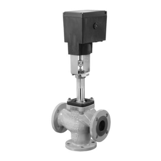
- Page 1 EB 8331-3 EN Translation of original instructions Type 3374 Electric Actuator Three-step version Edition January 2019...
- Page 2 Note on these mounting and operating instructions These mounting and operating instructions assist you in mounting and operating the device safely. The instructions are binding for handling SAMSON devices. The images shown in these instructions are for illustration purposes only. The actual product may vary.
-
Page 3: Table Of Contents
Contents Safety instructions and measures ..............1-1 Notes on possible severe personal injury ............1-4 Notes on possible personal injury ..............1-5 Notes on possible property damage .............1-6 Markings on the device ................2-1 Nameplate ....................2-1 Design and principle of operation ...............3-1 Fail-safe action ...................3-1 Versions .....................3-1 Additional equipment ..................3-2 3.3.1... - Page 4 Decommissioning ..................11-1 Removal ....................12-1 12.1 Construction with integrated yoke ...............12-1 12.2 Construction with ring nut ................12-2 Repairs ....................13-1 13.1 Returning the actuator to SAMSON ............13-1 Disposal ....................14-1 Certificates ....................15-1 Annex......................16-1 16.1 Parts for retrofitting and accessories ............16-1 16.2 After-sales service ..................16-2 EB 8331-3 EN...
-
Page 5: Safety Instructions And Measures
Therefore, operators must ensure that the actuator is only used in operating conditions that meet the specifications used for sizing the actuator at the ordering stage. In case operators intend to use the actuator in other applications or conditions than specified, contact SAMSON. SAMSON does not assume any liability for damage resulting from the failure to use the de- vice for its intended purpose or for damage caused by external forces or any other external factors. Î Refer to the technical data for limits and fields of application as well as possible uses. See the 'Design and principle of operation' section. - Page 6 Revisions and other modifications Revisions, conversions or other modifications of the product are not authorized by SAMSON. They are performed at the user's own risk and may lead to safety hazards, for example. Fur- thermore, the product may no longer meet the requirements for its intended use. Safety features Upon supply voltage failure, the Type 3374 Electric Actuator causes the valve to move to a certain fail-safe position. The fail-safe action of SAMSON actuators is specified on the actua- tor nameplate. Type 3374-21/-26/-31/-36...
- Page 7 Î For wiring, maintenance and repair, observe the relevant safety regulations. Referenced documentation The following documents apply in addition to these mounting and operating instructions: − Mounting and operating instructions of the valve on which the electric actuator is mount- ed, e.g. for SAMSON valves: u EB 5861 for Type 3260 Three-way Valve u EB 5868 for Type 3213 and Type 3214 Globe Valves u EB 8012 for Type 3241 Globe Valve, ANSI and JIS version u EB 8015 for Type 3241 Globe Valve, DIN version...
-
Page 8: Notes On Possible Severe Personal Injury
Safety instructions and measures 1.1 Notes on possible severe personal injury DANGER Risk of fatal injury due to electric shock. Î Before connecting wiring, performing any work on the device or opening the de- vice, disconnect the supply voltage and protect it against unintentional reconnec- tion. Î Only use power interruption devices that can be protected against unintentional reconnection of the power supply. -
Page 9: Notes On Possible Personal Injury
Safety instructions and measures 1.2 Notes on possible personal injury WARNING Crush hazard arising from moving parts. The electric actuator contains moving parts (actuator and plug stems), which can injure hands or fingers if inserted into the actuator. Î Do not insert hands or finger into the yoke while the valve is in operation. Î Disconnect the supply voltage and protect it against unintentional reconnection be- fore performing any work on the control valve. -
Page 10: Notes On Possible Property Damage
1.3 Notes on possible property damage NOTICE Risk of damage to the electric actuator due to the supply voltage exceeding the permissible tolerances. The Type 3374 Electric Actuator is designed for use according to regulations for low-voltage installations. Î Observe the permissible tolerances of the supply voltage. Risk of actuator damage due to excessively high tightening torques. -
Page 11: Markings On The Device
Markings on the device 2 Markings on the device 2.1 Nameplate SAMSON 3374- Electric Actuator Var.-ID Serial no. 0062 SAMSON AG, Germany Made in Germany Type Additional electrical equipment Configuration ID Mechanical limit contacts Serial number Supply voltage; power line frequency Power consumption Resistance transmitter... - Page 12 EB 8331-3 EN...
-
Page 13: Design And Principle Of Operation
Testing according to DIN EN 14597 The Types 3374 Electric Actuator with fail- safe action "actuator stem extends" is tested Fig. 3-2: Construction for mounting with ring nut (form A) by the German technical surveillance associ- ation (TÜV) according to DIN EN 14597 in combination with various SAMSON valves. The register number is available on request. EB 8331-3 EN... -
Page 14: Additional Equipment
Design and principle of operation 3.3 Additional equipment The actuator can be equipped with mechani- cal limit contacts or with resistance transmit- ters to influence the tasks of control equip- ment. 3.3.1 Mechanical limit contacts Optionally, the actuator can be equipped with two limit contacts. They consist of two changeover switches. -
Page 15: Technical Data
Design and principle of operation 3.4 Technical data Table 3-1: Technical data for Type 3374 Type 3374 Ring Ring Ring Version with Yoke Yoke Yoke Fail-safe action Without Extends Retracts Rated travel Stroking speed Standard mm/s 0.125 0.125 Fast mm/s 0.25 0.25... - Page 16 Design and principle of operation Type 3374 Permissible temperatures Ambient 5 to 60 °C Permissible temperatures Storage –25 to +70 °C Materials Housing and cover: Plastic (glass-fiber reinforced PPO) Weight kg (approx.) Safety Degree of protection IP 54 acc. to EN 60529, (IP 65 with three cable glands Suspended mounting position not approved Class of protection II according to EN 61140 Device safety According to EN 61010-1 Noise immunity According to EN 61000-6-2 and EN 61326-1 Noise emission According to EN 61000-6-3 and EN 61326-1...
-
Page 17: Dimensions In Mm
Design and principle of operation 3.5 Dimensions in mm Type 3374-10/-11/-21/-31 When the actuator stem is fully extended Type 3374 Dimension h Fig. 3-3: Dimensions for version with yoke (form B) EB 8331-3 EN... - Page 18 Design and principle of operation Types 3374-15/-26/-36 When the actuator stem is fully extended Type 3374 Dimension h Dimension h Fig. 3-4: Dimensions for version with ring nut (form A) EB 8331-3 EN...
-
Page 19: Shipment And On-Site Transport
4.2 Removing the packaging − Observe the storage instructions. from the actuator − Avoid long storage times. − Contact SAMSON in case of different storage conditions or long storage periods. Note Do not remove the packaging until immedi- ately before mounting and start-up. - Page 20 Shipment and on-site transport Storage instructions − Protect the electric actuator against exter- nal influences (e.g. impact). − Protect the electric actuator against mois- ture and dirt. − Make sure that the ambient air is free of acids or other corrosive media. − Observe the permissible storage tem- perature from –25 to +70 °C.
-
Page 21: Installation
Installation 5 Installation 5.1 Preparation for installation 5.1.1 Mounting orientation The control valve can be installed in the pipeline in any desired position. However, a sus- pended mounting position of the actuator is not permissible (see Fig. 5-1). 0...90° 0...90° Fig. 5-1: Mounting position 5.2 Mounting the actuator 5.2.1 Construction with integrated yoke Attachment − Series V2001 Valves (DN 15 to 80) − Type 3260 (DN 65 to 150) − Type 3214 (DN 65 to 100) EB 8331-3 EN... - Page 22 Installation Î Refer to Fig. 5-3. 1. Remove protective covers and unscrew Types 3374-10/-11/-21/-31 nut (6) from the valve. Connection with yoke Attachment to Series V2001 Valves, 2. Retract actuator stem (3) as described in Type 3260 (DN 65 to 150), the 'Operation' section (see Fig. 5-2). Type 3214 (DN 65 to 100) Actuating shaft Fig. 5-2: Actuating shaft for manual override...
-
Page 23: Construction With Ring Nut
(4) and yoke to the middle of the stem connector screw tight. nut (8) is achieved. Lock this position with the lock nut (9). Types 3374-15/-26/-36 Connection with ring nut 3. Retract actuator stem (3) as described in Attachment to Series 240 Valves the 'Operation' section (see Fig. 5-4). - Page 24 5. Align travel indicator scale (10) with the 250) middle of the stem connector (4) and screw tight. Î Refer to Fig. 5-6. 1. Retract actuator stem (3) as described in Types 3374-15/-26/-36 the 'Operation' section (see Fig. 5-6). Connection with ring nut Attachment to Type 3214 Valve (DN 125 to 250) Actuating shaft Fig. 5-6: Actuating shaft for manual override...
-
Page 25: Additional Equipment
Installation 5.3 Additional equipment We recommend applying a small amount of DANGER lubricant (e.g. Vaseline) to the spindles on Risk of fatal injury due to electric shock. the gear faces and to the sides of the cogs. Before installing electrical accessories, switch off the supply voltage and protect it against Note unintentional reconnection. - Page 26 Installation Intermediate gear Spindle gear Serrated ring (for 1) Tension spring Serrated ring (for 10) 10 Shim Fig. 5-8: Basic unit: order no. 1400-8829 Serrated ring Spacer Snap ring 16 Screw WN 1412 17 Terminal board 18 Adjustment gear 19 Contact cam 20 Cam holder Fig. 5-9: Mechanical limit contacts order no.
- Page 27 Installation Actuators without resistance transmitters 10. Turn both contact cams (19) on the cam holder (20) as illustrated in Fig. 5-12 Î Refer to Fig. 5-10. corresponding with the position of the 1. Unscrew screws on housing cover and actuator stem. take the cover off the actuator. 11. Slide the cam holder (20) with both con- 2.
- Page 28 Installation 11.1 11.2 Intermediate gear Spindle gear Serrated ring Tension spring Spacer 11.1 Spindle 1 11.2 Spindle 2 Actuator board Bearing sleeve Terminal board Adjustment gear Contact cam Cam holder Fig. 5-10: Installing the limit contacts EB 8331-3 EN...
-
Page 29: Adjusting The Limit Contacts
Installation Actuators with resistance transmitters 1. Unscrew screws on housing cover and take the cover off the actuator. 2. Move the actuator stem to the end posi- tion depending on the fail-safe action "actuator stem extends" or "actuator stem retracts" (see the 'Operation' sec- tion). - Page 30 Installation 11.2 Fig. 5-11: Retrofitting limit contacts (when resistance transmitters are already installed) When actuator stem retracted Actuator stem re- Actuator stem tracted extended Fig. 5-12: Alignment of contact cam and cam holder When actuator stem extended Fig. 5-13: Alignment of the contact cam unit 5-10 EB 8331-3 EN...
-
Page 31: Installing The Resistance Transmitters
Installation 5.3.3 Installing the resistance dle 1 (11.1), mount the serrated ring (3) and push it down as far as it will go. transmitters 3. Place the tension spring (4) onto the An actuator board with the corresponding spindle 3 (11.3), ensuring that the long resistance transmitters and gear wheels is re- wire of the tension spring rests on the quired for a resistance transmitter retrofit. - Page 32 Installation Actuators with limit contacts 3. Unscrew fastening screws. Slide the actu- ator board (12) from its guiding to the 1. Unscrew screws on housing cover and right. Slightly lift the board and continue take the cover off the actuator. pushing it further towards the cable en- 2.
-
Page 33: Adjusting The Resistance Transmitter
Installation 5.3.4 Adjusting the resistance Zero adjustment transmitter 1. Use the motor or manual override to move the valve to the desired end posi- The gears of the resistance transmitters (22) tion. and (23) must be put onto their shafts to cor- 2. - Page 34 5-14 EB 8331-3 EN...
-
Page 35: Electrical Connection
Electrical connection 6 Electrical connection DANGER Risk of fatal injury due to electric shock. − Upon installation of the electric cables, you are required to observe the regulations concerning low-voltage installations according to DIN VDE 0100 as well as the regulations of your local power supplier. −... - Page 36 Electrical connection Mechanical limit contacts Controller 41 44 42 51 54 52 – Resistance transmitters 81 82 83 91 92 93 Type 3374 Actuator Fig. 6-1: Electrical connection Table 6-1: Cables and stranded wires that can be used Cable Cross section Single-wire H05(07) V-U 0.2 to 1.5 mm² Fine-wire H05(07) V-K 0.2 to 1.5 mm²...
-
Page 37: Start-Up
Start-up 7 Start-up Once the actuator has been mounted correctly and the wiring has been performed as described in the 'Electrical connection' section, the electric actuator is ready for use and can be controlled by a three-step signal (see specifications in technical data). EB 8331-3 EN... - Page 38 EB 8331-3 EN...
-
Page 39: Operation
Operation 8 Operation 8.2 Mechanical override After connecting the supply voltage, the To operate the manual override, place a actuator is ready for use. 4 mm hex wrench on the red actuator shaft located at the side of the housing (see 8.1 Three-step mode Fig. 8-2). Turn the hex wrench clockwise to move the actuator in 'aL' direction and coun- In three-step mode, the actuator stem is terclockwise to move it in the 'eL' direction moved in the corresponding direction by ap-... - Page 40 EB 8331-3 EN...
-
Page 41: Malfunctions
Malfunctions 9 Malfunctions Î Troubleshooting (see Table 9-1). Note Contact SAMSON's After-sales Service for malfunctions not listed in the table. Table 9-1: Troubleshooting Error Possible reasons Recommended action Actuator stem does not move. Actuator is blocked. Î Check attachment. Î Remove the blockage. - Page 42 EB 8331-3 EN...
-
Page 43: Servicing
Servicing 10 Servicing Note The electric actuator was checked by SAMSON before it left the factory. − The product warranty becomes void if service or repair work not described in these instructions is performed without prior agreement by SAMSON's After-sales Service. - Page 44 10-2 EB 8331-3 EN...
-
Page 45: Decommissioning
Decommissioning 11 Decommissioning To decommission the electric actuator for repair work or disassembly, proceed as follows: DANGER Î Put the control valve out of operation. Risk of fatal injury due to electric shock. See associated valve documentation. Before disconnecting live wires, switch off the supply voltage at the actuator and protect it against unintentional reconnection. - Page 46 11-2 EB 8331-3 EN...
-
Page 47: Removal
Removal 12 Removal 2. Retract actuator stem as described in the 'Operation' section. 3. Undo the stem connector parts between DANGER the plug and actuator stems. Risk of fatal injury due to electric shock. 4. Loosen the nut at the yoke. −... -
Page 48: Construction With Ring Nut
Removal 12.2 Construction with ring nut Î The actuator stem moves to the fail-safe position. Actuator without fail-safe action 7. Disconnect the wires of the connecting 1. Disconnect the supply voltage and pro- lines. tect it against unintentional reconnection. 8. Remove the connecting lines. 2. -
Page 49: Repairs
NOTICE Risk of actuator damage due to incorrect repair work. Î Do not perform any repair work on your own. Î Contact SAMSON's After-sales Service for repair work. 13.1 Returning the actuator to SAMSON Defective actuators can be returned to SAMSON for repair. - Page 50 13-2 EB 8331-3 EN...
-
Page 51: Disposal
Disposal 14 Disposal We are registered with the German national register for waste electric equipment (stiftung ear) as a producer of electrical and electronic equipment, WEEE reg. no.: DE 62194439 Î Observe local, national and internation- al refuse regulations. Î Do not dispose of components, lubricants and hazardous substances together with your other household waste. - Page 52 14-2 EB 8331-3 EN...
-
Page 53: Certificates
Certificates 15 Certificates The following certificate is shown on the next page: − EU declaration of conformity The certificate shown was up to date at the time of publishing. The latest certificate can be found on our website at: u www.samsongroup.com > Products & Applications > Product selector > Actuators > 3374 EB 8331-3 EN 15-1... - Page 54 Certificates EU declaration of conformity 15-2 EB 8331-3 EN...
-
Page 55: Annex
Resistance transmitters See Table 16-1 Gear wheel for resistance transmitter PCB Order no. 1992-5885 Accessories Set with three cable glands M20x1.5 with metal nut (SW 23/24) Order no. 1400-8828 Table 16-1: Resistance transmitters · Selecting the actuator board 1) Type 3374 0.125 mm/s Order no. 1180-9601 Order no. 1180-9607 230 V/50 Hz 0.25 mm/s Order no. 1180-9604 Order no. 1180-9610 230 V/60 Hz Order no. 1180-9637 Order no. -
Page 56: After-Sales Service
E-mail contact You can reach our after-sales service by e-mail at aftersalesservice@samsongroup. com. Addresses of SAMSON AG and its subsid- iaries The addresses of SAMSON, its subsidiaries, representatives and service facilities worldwide can be found on our website (u www.samsongroup.com) or in all... - Page 60 EB 8331-3 EN SAMSON AKTIENGESELLSCHAFT Weismüllerstraße 3 · 60314 Frankfurt am Main, Germany Phone: +49 69 4009-0 · Fax: +49 69 4009-1507 samson@samsongroup.com · www.samsongroup.com...
Need help?
Do you have a question about the 3374 and is the answer not in the manual?
Questions and answers