
Subscribe to Our Youtube Channel
Related Manuals for DynaGen TG410


Summary of Contents for DynaGen TG410
- Page 1 TG410 User Manual Manual Revision: 5.0.0 Min. FW Revision: 1.82 Date Released: 14/03/2017 © 2017 DynaGen Technologies Inc...
-
Page 2: Table Of Contents
Pull and Hold Coil ..................................32 Sensors ....................................33 4.4.1 Engine Temperature ..................................33 4.4.2 Oil Pressure ..................................34 4.4.3 Fuel Level ..................................35 4.4.4 Engine Speed ..................................35 Front Panel Speed Control ..................................37 © 2017 DynaGen Technologies Inc... - Page 3 Communications ....................................62 4.7.1 CAN Bus (J1939) ..................................62 4.7.2 MOD Bus (RS485) ..................................64 Other Config ....................................64 4.8.1 Password ..................................64 4.8.2 Settings Name ..................................64 4.8.3 Process Control ..................................65 5 Troubleshooting © 2017 DynaGen Technologies Inc...
- Page 4 User Guide TOUGH Series Manual © 2017 DynaGen Technologies Inc...
-
Page 5: Introduction
The TOUGH series controllers are designed to provide complete control, protection, AC metering, and engine instrumentation for both standard and electronic engines. The module is easily configured using either the front panel buttons or our DYNAGEN Configurator software. TOUGH series controllers are ideally suited for severe duty applications where reliability is critical such as mobile and stationary generators. -
Page 6: Specifications
Do not connect more than 600VAC to the controller. Damage may result. AC Current 0 ~ 5A (Current Transformer), Accuracy: 1% Full Scale Communications SAE J1939 (Tier II, III, IV) Isolated RS485 (Slave Modbus RTU) TOUGH Series Manual © 2017 DynaGen Technologies Inc... -
Page 7: Installation
If applicable, snap the RelayPak (RP100) to the back of the controller. Place one side of the RP100's tabs into the slot on the back of the controller and, without pushing on the relays, snap the other tab into place. TE Series Cutout (Not To Scale) TOUGH Series Manual © 2017 DynaGen Technologies Inc... -
Page 8: General Wiring Notes
Low impedance sensor input (0 - 750Ohm) J4-14 Sensor Input C Universal sensor input (0 - 750Ohm, 0 - 7,500Ohm, 0 - 5 VDC, 4 - 20mA). See Universal Sensor section for more information. TOUGH Series Manual © 2017 DynaGen Technologies Inc... - Page 9 Provides ground return for 2-wire sensors J3-8 Sensor Input D Universal sensor input (0 - 750Ohm, 0 - 7,500Ohm, 0 - 5 VDC, 4 - 20mA) See Universal Sensor section for more information. TOUGH Series Manual © 2017 DynaGen Technologies Inc...
- Page 10 Connect to current transformer for Phase B of the generator J5-3 Phase C Connect to current transformer for Phase C of the generator J5-4 CT Common Connect to the commons of the current transformers TOUGH Series Manual © 2017 DynaGen Technologies Inc...
-
Page 11: Wiring Harnesses
Installation Wiring Harnesses TOUGH Series Manual © 2017 DynaGen Technologies Inc... -
Page 12: Typical Wiring Diagram
Installation Typical Wiring Diagram TOUGH Series Manual © 2017 DynaGen Technologies Inc... -
Page 13: Typical Wiring Diagram With Relaypak
Installation Typical Wiring Diagram with RelayPak TOUGH Series Manual © 2017 DynaGen Technologies Inc... -
Page 14: Wiring Considerations
Close +BAT. The trigger can be set to any of four options but Close +BAT gives the best immunity to noise. For runs over 20ft (6.1m) especially in noisy environments Dynagen recommends connecting the Start/Stop to an external relay. The relay needs to be located as close to the controller as possible. -
Page 15: Universal Sensor
NOTE: A TVS (i.e. varistor) is required if the battery is different than the battery the controller is powered from. The controller's TVS cannot protect the sensor input from transients in this case. TOUGH Series Manual © 2017 DynaGen Technologies Inc... -
Page 16: Can Bus Wiring
· Enable the Auto Power ECM setting in the Communications -> CAN Bus (J1939) menu will cause the fuel output to turn on in Auto mode and stay on. ECM Wiring TOUGH Series Manual © 2017 DynaGen Technologies Inc... - Page 17 Installation TOUGH Series Manual © 2017 DynaGen Technologies Inc...
-
Page 18: Modbus Wiring
The above cable must terminate no farther than 6 inches from the controller's RS485 (Modbus) Termination at the Controller connector. Three inches is ideal. Refer to the Example wiring diagram for a wiring example. TOUGH Series Manual © 2017 DynaGen Technologies Inc... -
Page 19: Current Transformers
NOTE: If readings are unstable with the configuration shown below, attempt connecting the CT Common's black wire to the negative terminal of the battery. Ensure the connecting wire is as short as possible. TOUGH Series Manual © 2017 DynaGen Technologies Inc... - Page 20 Installation TOUGH Series Manual © 2017 DynaGen Technologies Inc...
-
Page 21: Relaypak (Optional)
UL conditions of acceptability. WARNING: You must use relays in the RelayPak that are suitable for the system voltage. Example: 12V relays in a 12V system and 24V relays in a 24V system. TOUGH Series Manual © 2017 DynaGen Technologies Inc... - Page 22 Installation TOUGH Series Manual © 2017 DynaGen Technologies Inc...
-
Page 23: Using The Controller
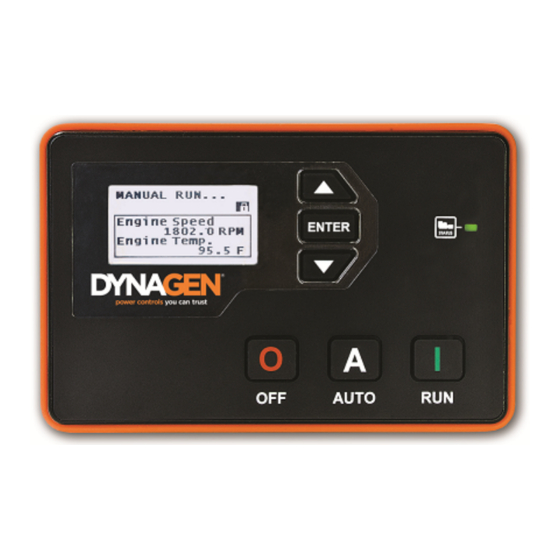
Used for moving around in the menu, changing a setting's value, or changing the currently displayed parameter page . Generator/Engine LED Green = Engine running with no issues Amber = Engine running with warnings Red = Engine shut down on failure TOUGH Series Manual © 2017 DynaGen Technologies Inc... -
Page 24: Modes, Starting And Stopping
ECM on an electronic engine so a diagnostic tool can obtain information from the ECM. WARNING: See the Using Cooldown Mode section for more information on how it affects starting and stopping. TOUGH Series Manual © 2017 DynaGen Technologies Inc... -
Page 25: Using Cooldown Mode
Temp applications. Low Oil Switched input set to "Oil Pres. Warn" function. Low oil pressure warning. Pressure Switched Inputs. Triggered if switched input is active during the RUN mode. TOUGH Series Manual © 2017 DynaGen Technologies Inc... -
Page 26: Failures
J1939 Start Notice Controller started from J1939 using the second J1939 start/stop method. Refer to the J1939 user guide for more information. This is often used by telemetry devices to start/stop the controller. TOUGH Series Manual © 2017 DynaGen Technologies Inc... -
Page 27: Settings
When enabled, allows a user to start the engine using the run button while in the OFF mode. When disabled the controller must be placed in AUTO mode before the run button can start the engine. TOUGH Series Manual © 2017 DynaGen Technologies Inc... -
Page 28: Switched Inputs
Controller displays 'High Fuel Level' warning when active. Lamp Test Global Controller performs lamp test when active. If the controller is in the FAILURE mode the LED will remain red. The only indication that the lamp test is TOUGH Series Manual © 2017 DynaGen Technologies Inc... - Page 29 Input is active when neither +Battery or Ground is present at the terminal. NOTE: When running wires over long distances (over 20ft / 6.1m), it is recommended to use +BATTERY as the trigger method. TOUGH Series Manual © 2017 DynaGen Technologies Inc...
-
Page 30: Configurable Inputs
Ready) failures are present. Delay to Start Delay to Start Timer Active when the Delay to Start timer is active. Glowplug Preheat, Midheat, Active during the Preheat, Midheat and Postheat timers. Postheat TOUGH Series Manual © 2017 DynaGen Technologies Inc... - Page 31 AC Under Voltage AC Over Voltage Over Current Fuel In Basin Battery Charger Fault Configurable Warning 1 Configurable Warning 2 Auxiliary Sensor 1 Auxiliary Sensor 2 Auxiliary Sensor 3 Auxiliary Sensor 4 TOUGH Series Manual © 2017 DynaGen Technologies Inc...
- Page 32 Low Coolant Level Low Air Pressure Low Hydraulic Pressure Under Frequency Over Frequency AC Under Voltage AC Over Voltage Over Current (TG410 only) ECM Communication Failure Configurable Failure 1 Configurable Failure 2 Config Fail 3 Auxiliary Sensor 1 Auxiliary Sensor 2...
-
Page 33: Group Outputs
When any of the functions in a group is active (OR logic), the assigned switched output will be active. Group Functions Name Active Mode Description Group #1 Group Dependent Must be set from DYNAGEN Configurator software. Group #2 Group Dependent Must be set from DYNAGEN Configurator software. Group #3 Group Dependent Must be set from DYNAGEN Configurator software. -
Page 34: Sensors
Calibrate a sensor by using the offset to correct errors. Only applies if Sensor Type has been set to a sender. Setpoints > Bypass Time 0 ~ 90 seconds Amount of time to bypass warnings and failures after engine has started. TOUGH Series Manual © 2017 DynaGen Technologies Inc... -
Page 35: Oil Pressure
Reading at which a "Low Oil Pressure" failure occurs. Only (0.7 ~ 682.6kPa) applies if Sensor Type has been set to a sender. Note: All pressure settings are entered in terms of psi. TOUGH Series Manual © 2017 DynaGen Technologies Inc... -
Page 36: Fuel Level
300 ~ 2000 RPM in 1 Speed at which the engine runs when it is idling. RPM increments Speed Settings > Tooth Count 1 ~ 600 (Mag Pickup only) Number of teeth on the flywheel. TOUGH Series Manual © 2017 DynaGen Technologies Inc... - Page 37 The speed is not monitored during delay-to-start or preheat as this provides some degree of protection against spurious signals due to noise. The fuel input is turned on at the start of preheat and often powers external equipment that can cause noise. TOUGH Series Manual © 2017 DynaGen Technologies Inc...
-
Page 38: Front Panel Speed Control
Tsc1 RPM/s Sensors > Engine Speed > Disable, 10 ~ Ignore this setting. Refer to the J1939 reference manual for RPM Control 300 RPM/s in information on this setting. 10 RPM/s increments TOUGH Series Manual © 2017 DynaGen Technologies Inc... -
Page 39: Battery Level
NOTE: When the engine is running, the battery voltage will equal the alternator charging voltage. The actual open- circuit battery voltage may be lower than displayed. Battery Recharge Sequence TOUGH Series Manual © 2017 DynaGen Technologies Inc... - Page 40 Settings TOUGH Series Manual © 2017 DynaGen Technologies Inc...
-
Page 41: Auxiliary Sensors
(Only applies if Func. Select is not set to Fault Monitor) The amount 1 ~ 6000 , 1 minute of time to turn on the auxiliary switched output or run the controller increments before turning off the output or shutting down the controller. TOUGH Series Manual © 2017 DynaGen Technologies Inc... - Page 42 The resolutions are given below. Sensor Unit Type Comparison Resolution Temperature Pressure 1 psi Level TOUGH Series Manual © 2017 DynaGen Technologies Inc...
- Page 43 Turn off High sensor needs to rise the sensor needs output when the sensor drops above to turn on the to drop below to below a certain value. output. turn off the output. TOUGH Series Manual © 2017 DynaGen Technologies Inc...
- Page 44 Trigger warnings and/or failures on Fault Warnings/ the sensor. Monitor Failures Do not perform any actions on the Fault sensor value. Just display the Monitor Display value to the user. (Disable all only warnings and failures) TOUGH Series Manual © 2017 DynaGen Technologies Inc...
-
Page 45: Fault Monitor Example
275°F warning threshold, activating the warning display. The engine will continue to run because it has not reached the 350°F failure threshold. At 20 minutes run time, the temperatures falls below the warning threshold and the warning disappears. TOUGH Series Manual © 2017 DynaGen Technologies Inc... -
Page 46: Start On Low Example
The chart above shows the connection between a battery bank and time. At approximately 80 minutes time, the voltage falls below the 10.5V start threshold causing the engine to start. The engine runs for the 40 minutes active time regardless of the voltage reading and then shuts down. TOUGH Series Manual © 2017 DynaGen Technologies Inc... -
Page 47: Output On High Example
325°F start threshold and the fan turns on. The fan continues to run as the temperature declines. When the temperature falls below the 200°F stop threshold, the fan turns off. TOUGH Series Manual © 2017 DynaGen Technologies Inc... -
Page 48: Sensor As A Switch
Custom Sensor Tables are created using the RapidCore Configuration Software when using a sensor that is not supported by DYNAGEN. The configurator has the ability to create these custom tables, allowing the controller to properly read the sensor data. NOTE: Custom sender tables can only be created when using the configuration software. -
Page 49: Timers
Cooldown Delay. OFF Button Function Cooldown The function the OFF button on the front panel performs while Shutdown engine is running. See the OFF Button Function section for Force Cooldown more information. TOUGH Series Manual © 2017 DynaGen Technologies Inc... -
Page 50: Preheat Mode
Tip: It takes up to 2 seconds for the false restart to be triggered. In addition it takes time for the engine speed to drop below 250RPM. These should be measured and added to the desired False Check setting. TOUGH Series Manual © 2017 DynaGen Technologies Inc... -
Page 51: Off Button Function
WARNING: If the controller receives a command to start from the remote start or front panel run button while in Cooldown, it will leave the Cooldown mode and go back to Running mode. TOUGH Series Manual © 2017 DynaGen Technologies Inc... -
Page 52: Idle
Timers > Engine Logic > 1 to 100 F, 1 (Warm-up Idle) Always exit idle when the Idle Settings increments temperature is above this setting. Cooldown Idle Timers > Engine Logic Disable Idle during cooldown. Enable TOUGH Series Manual © 2017 DynaGen Technologies Inc... -
Page 53: Idle Inhibit
(e.g. February 21 and a date of 31 is selected) the exerciser will run on the next month to have that date (e.g. 31rst of March) at the hour specified. TOUGH Series Manual © 2017 DynaGen Technologies Inc... - Page 54 If the controller is in the OFF mode, if the emergency stop is activated, or if the start inhibit is active then the exerciser will not run. The event, "Bypass Exerciser", will be logged in the event log and the exerciser will run again at the next scheduled time as determined by the "Repeat Days" setting. TOUGH Series Manual © 2017 DynaGen Technologies Inc...
-
Page 55: Weekly Scheduler
To determine the amount of time until the next scheduled maintenance, follow these menu steps: Main Menu -> Device Info. -> Maintenance Maintenance counter is disabled if '----' is displayed. A negative number indicates the amount of time since maintenance timer expired. TOUGH Series Manual © 2017 DynaGen Technologies Inc... -
Page 56: Ac Monitor
Reading at which a failure occurs. *NOTE: 800 VAC applies to software logic only. Do not exceed 600 VAC on the AC Voltage terminals including during over voltage warning and failure conditions. TOUGH Series Manual © 2017 DynaGen Technologies Inc... - Page 57 208.3 VAC. Use the formula below to determine the scaling factor. Scaling Factor = Multimeter Reading / Controller Reading Scaling Factor = 208.4 VAC / 206.3 VAC Scaling Factor = 1.010 TOUGH Series Manual © 2017 DynaGen Technologies Inc...
-
Page 58: Ac Voltage Select
Setpoints > Low Warn (Under- Disable, 20 ~ 99% Reading at which a warning occurs. Frequency Warning) Setpoints > Low Fail (Under- Disable, 20 ~ 99% Reading at which a failure occurs. Frequency Failure) TOUGH Series Manual © 2017 DynaGen Technologies Inc... -
Page 59: Rpm / Frequency Select
Active Secondary RPM / 50Hz NOTE: If enabled, the J1939 TSC1 PGN will be broadcasted according to the selected speed. Otherwise only the warning and failure setpoints are affected by this function. TOUGH Series Manual © 2017 DynaGen Technologies Inc... -
Page 60: Generator Current
Voltage Select inputs. Auto Scaling > 3-Phase (1) 0.500 ~ 2.250 Auto Scaling > 3-Phase (2) 0.500 ~ 2.250 Auto Scaling > 3-Phase (3) 0.500 ~ 2.250 Dummy Load [Menu] Dummy Load. TOUGH Series Manual © 2017 DynaGen Technologies Inc... -
Page 61: Basic Alarms
Dial Setting) of the trip to over current. IDMT Settings > IDMT Reset 1 ~ 600 seconds How long the current must drop and stay below the rated current to reset the IDMT. TOUGH Series Manual © 2017 DynaGen Technologies Inc... -
Page 62: Load Imbalance
The load imbalance formula is given as: For three phase: For single phase: Where are the actual current measured by the controller. Note: Phase Imbalance is the same as load imbalance. TOUGH Series Manual © 2017 DynaGen Technologies Inc... -
Page 63: Dummy Load
4.6.3.5 EPS Supplying Load The EPS (Emergency Power System) Supplying load sets a flag in Modbus register 40006 to indicate to the DynaGen RA400 remote annunciator that the generator is actively supplying power. If this flag is set the RA400 will light it's EPS Supplying Load indicator. - Page 64 Select the SPN conversion method. Version 2 Version 3 EMS2B Frequency Select Primary For Volvo EMS2B Engine Control Modules only. Secondary EMS2B Accelerator Pedal 40.0 ~ 60.0% For Volvo EMS2B Engine Control Modules only. TOUGH Series Manual © 2017 DynaGen Technologies Inc...
-
Page 65: Mod Bus (Rs485)
Options in the settings tab of the Configuration Software. There is no controller menu to set this ID. It can be up to 12 characters long. The Configuration Name can be viewed in the Device Info > About TG410/TG350 menu. It is labeled ID. TOUGH Series Manual... -
Page 66: Process Control
High Edge. Thresholds > Min RPM (Low 500 ~ 4000 RPM in 1 The fixed RPM that should be used when the level falls below the Limit RPM) RPM increments Low Edge. TOUGH Series Manual © 2017 DynaGen Technologies Inc... -
Page 67: Troubleshooting
Contacting DYNAGEN can be done by any of the methods below. Technical support is offered Monday - Friday, 8:00am - 4:00pm (EST). If you are unable to contact one of our engineers, please leave a message and they will return your call as soon as possible.
Need help?
Do you have a question about the TG410 and is the answer not in the manual?
Questions and answers