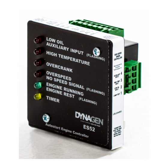
DynaGen ES52 Installation And User Manual
Auto start engine controller
Hide thumbs
Also See for ES52:
- Installation and user manual (21 pages) ,
- Installation manual (3 pages)

Related Manuals for DynaGen ES52


Summary of Contents for DynaGen ES52
- Page 1 ES52 Auto Start Engine Controller Installation and User Manual for the ES52 Auto Start Engine Controller. Full Version File: MAN-0001 R4.0, ES52 User Manual.doc Date: August 2017 Thank You For Purchasing This DynaGen Product...
- Page 2 In case of damage, immediately contact the carrier and request that an inspection report be filed prior to contacting DynaGen. All returned items are to be shipped prepaid and include a Return Material Authorization (RMA) number issued by DynaGen.
- Page 3 ES52 Family of Products – Speed Signal Connector Change Notice This change will take effect in March of 2011 for all new orders. This applies only to the 2-wire speed signal connection (for mag pickup or generator output). All other connectors and controller features remain unchanged.
- Page 4 Lamp Test terminal: Actual unit weight: 0.67 lb (0.30kg) Shipping weight: 1 lb (0.45kg) 3.302” x 3.342” x 1.8” Unit dimensions: 4” (10.16cm) x 4” (10.16cm) x 3” (7.62cm) Shipping dimensions: Operating & Installation Manual for the ES52 Engine Controller...
-
Page 5: Table Of Contents
OPERATION ..............................19 ES52 S ....................19 TARTUP HUTDOWN EHAVIOR ....................... 19 PEED ESTART EATURE LED INDICATIONS ......................19 RONT ANEL TROUBLESHOOTING GUIDELINES ......................21 TECHNICAL NOTES ON FREQUENTLY ASKED QUESTIONS ............23 Operating & Installation Manual for the ES52 Engine Controller... -
Page 6: Introduction
• Warm Up: Turns an output on which can control a load device. Warm Up timer output is provided on all ES52 units via Terminal 19. Warm Up timer is fixed at 2 Minutes. • Small Size: 3.302” x 3.342” x 1.842” 0.67lbs. -
Page 7: Wiring Installation Guidelines
Start/Stop Connection 10 A Fuel Solenoid/Pilot Relay 300mA Timer Output 13 to 18 300mA Annunciation Outputs 300mA Warmup Output 300mA Annunciator Common Ground Only (DO NOT use this as main ground connection) Operating & Installation Manual for the ES52 Engine Controller... -
Page 8: Wiring Guidelines
2.2 Wiring Guidelines 1. WARNING: DO NOT apply external voltage to annunciator outputs (terminals 13 to 18). This will damage the ES52. If this may occur in your application, place a diode in series with each affected annunciator output. 2. DO NOT use wire smaller than 18 AWG. -
Page 9: Terminal Descriptions
The power for the crank output and fuel output is obtained from this terminal. If the 20A fuse is blown the ES52 will not start. Fuel output provides 10Amps maximum. Fuel output closes to +12/24 VDC when start signal is actuated, and opens when either an Engine failure is detected or when stop signal Operating &... -
Page 10: General Wiring Diagram
A diode across Auto and Start/Stop terminals is required on versions of the ES52 with the Cool- Down feature (ES52 EI, FE, and LT variants). See the tech notes section at the end of this manual for further information. The standard ES52 version does not require this. - Page 12 Operating & Installation Manual for the ES52 Engine Controller...
-
Page 13: Adjustments And Setup Procedures
To decrease it, turn it counter-clockwise. On board Pots are 20 turns nominal, therefore turn pots fully 20 turns to ensure that you are at either the minimum or maximum setting. Potentiometers are shown below as they appear on the rear of the ES52 series units 1. Crank Disconnect 2. Over-Speed 3. -
Page 14: Factory Settings
3. 10s Timer output, Timer set to preheat functionality. 4. DIP switches one and two ON. All other OFF. The steps to calibrate the ES52 controller to a specific system are as follows: 1. Select the Engine Speed Range (DIP switches 4, 5) 2. -
Page 15: Low Oil Pressure Switch Verification
If the engine has been previously running, and more than 5 minutes of rest has elapsed. If DIP switch 6 is set to the off position, the ES52 does not provide oil verification. The ES52 goes immediately into cranking; it will then check for a low oil failure condition after the oil bypass period has elapsed. -
Page 16: Adjusting Timer Duration
Increase or decrease pot setting as required pot resolution is 12.8 seconds/turn. e) Return to step a. Re-connect wires to the Timer terminal #12 and Crank terminal # 5 before proceeding to Step 5. Operating & Installation Manual for the ES52 Engine Controller... -
Page 17: Crank And Crank Rest
The Loss of Speed While Cranking portion can be disabled via DIP switch # 9. When the DIP switch is in the UP or ON position, the Loss of Speed While Cranking function is enabled. When Operating & Installation Manual for the ES52 Engine Controller... -
Page 18: Warm Up
4500 HZ - .8V (800 mV) 2.5.10 Warm up A Warm up timer is provided on all ES52 series engine controllers. Terminal 19 is the Warm up timer output. This output energizes 2 minutes after the engine running LED turns on (i.e. Speed above crank disconnect setting). -
Page 19: Operation
LEDs flashing) after 30 to 40 seconds. 2. If speed is not zero during engine rest the ES52 will not crank until it is zero. It will sit in engine rest for 30 to 40 seconds and then go into failure (alternating over crank and over speed LEDs flashing). - Page 20 4 & 5. 2. Crank disconnect set too high Over-speed and over crank LED's (above over speed setting). flash alternately 3. Speed was not zero at the start of cranking (timeout). Operating & Installation Manual for the ES52 Engine Controller...
-
Page 21: Troubleshooting Guidelines
Engine starts, but running Improper speed range setting Check to ensure that controller is set to LED does not illuminate. proper speed range (DIP switches 4,5) Operating & Installation Manual for the ES52 Engine Controller... - Page 22 If the neutral from the generator output cable. is not grounded, attach it to ground at generator. Operating & Installation Manual for the ES52 Engine Controller...
-
Page 23: Technical Notes On Frequently Asked Questions
ES52 because the controller remains in run mode and senses that the generator has stopped. This would be indicated by a Flashing Overspeed LED. By leaving the ES52 OFF for 10 seconds before it is returned to the Auto setting the memory will be cleared and it will function as intended. - Page 24 ES52 controller. The step-down transformer acts to reduce the false speed signal on the line to a level that the engine controller will not recognize as the engine running.
- Page 25 4. Connecting ES52 to a Transfer Switch (or remote device) The ES52 remote start contacts carry high current, up to 20A peak during starting (for more info see RSC1 and RSC2 in section 2.3 on page 9). If necessary use an external normally open relay to limit the current to the remote device.
Need help?
Do you have a question about the ES52 and is the answer not in the manual?
Questions and answers
how to connect the speed sensing wire to generator ?
To connect the speed sensing wire to a DynaGen ES52 generator:
1. Use a step-down transformer with a primary input of 120 or 240 VAC (depending on generator output) and a secondary output of 12 VAC.
2. Connect the primary side of the transformer to the generator output (line to neutral).
3. Connect the two wires from the secondary side of the transformer to the two speed sensing terminals on the ES52 controller using a twisted pair.
4. Ensure the transformer is around 24VA in size.
This setup reduces false speed signals to a level the controller does not recognize as the engine running.
This answer is automatically generated