
Related Manuals for DynaGen VTSC100


Summary of Contents for DynaGen VTSC100
- Page 1 VTSC100 Transfer Switch Controller VTSC100 Transfer Switch Controller Installation and User Manual Full Version File: MAN-0068 R1.4, VTSC100 User Manual.doc (September 2013)
- Page 2 In case of damage, immediately contact the carrier and request that an inspection report be filed prior to contacting DynaGen. All returned items are to be shipped prepaid and include a Return Material Authorization (RMA) number issued by DynaGen.
-
Page 3: Table Of Contents
Test point measurements 120/277 System Voltage Setting 50/60 Hertz setting Load/No load Over/Under Voltage setting Over/Under Frequency setting DIP SWITCH SETTING – MASTER CHART MANUAL TEST CONFIGURATION LED INDICATIONS LOGIC SEQUENCE Operating & Installation Manual for the VTSC100 Transfer Switch Controller... -
Page 4: Introduction
(available on 600A – 1250A), normal to emergency delay, emergency to normal delay, and engine cooldown. Simple potentiometer variations will determine the amount of time the VTSC100 will wait before activating specific outputs to control transfer switch conditions. Test points are provided on the VTSC100 for the accurate calibration of time delays. -
Page 5: Specifications
Included 8.511” x 3.75” x 1.7” Overall Dimensions *Feature only included on VTSC100-(240/480)-(12/24)-D Boards. Not on X types. One of the connected L-N phases must be below the under-voltage threshold to initiate transfer sequence. Operating & Installation Manual for the VTSC100 Transfer Switch Controller... - Page 6 The product Number Identification Table (see Table 1) provides the required information. example is offered to initially simplify the process. A product number VTSC100-XXX –XX-X would consist of a combination of information from the following table. TABLE1: IDENTIFICATION TABLE...
-
Page 7: Wiring Guidelines
The remote start connections from the timer module are internally fused. If fusing is replaced, use a 10 AMP automotive style fuse. Do not switch AC voltages with remote start connections from timer module. 6. Jumpers must be installed in the 12/24VDC jumper location on the VTSC100 for 12VDC operation. 12/24 VDC OPERATION The VTSC100 controller is designed to operate in a 12 OR 24 VDC system voltage. -
Page 8: Terminal Description
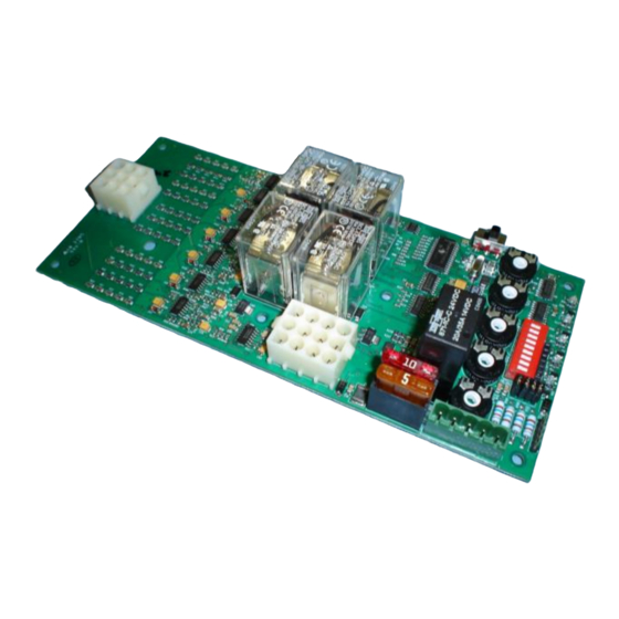
Emergency Output B1 J3-5 Trip Coil AT1 J3-6 Trip Coil BT1 J3-7 Normal A 120V J3-8 Normal A 120V J3-9 Exerciser Input J3-10 Normal Output A1 J3-11 Not used J3-12 Exerciser Ground Operating & Installation Manual for the VTSC100 Transfer Switch Controller... - Page 9 VTSC100 GENERAL LAYOUT *Drawing not to scale Operating & Installation Manual for the VTSC100 Transfer Switch Controller...
-
Page 10: Timer Settings
Completely isolate all sources of AC power from controller and transfer switch mechanism before making any adjustments. All necessary timing functions of the VTSC100 are configurable through the use of on-board potentiometers (POTS). Each pot has a 270 degree adjustment rotation, and can be increased by turning the pot clockwise and decreased by turning the pot counter-clockwise using the included pot adjustors. - Page 11 When the VTSC100 recognizes that the transfer switch is in the normal position after an emergency to normal transfer, the generator will continue to run under a no load condition until the engine cool time delay has expired.
-
Page 12: Tdes
Test Point voltage = 1.5625 VDC for TDES Test point #1 = TDEC Test point #2 = TDES Test point #3 = TDNE Test point #4 = TDEN Test point #5 = TDNP Operating & Installation Manual for the VTSC100 Transfer Switch Controller... - Page 13 120/240 and 277/480 VAC systems require specific hardware, so simply adjusting this setting in the field will not convert the system voltage of the board. The dip switch in location #1 on the VTSC100 is used at the factory to set the unit for 120/240 or 277/480 VAC systems.
-
Page 14: 50/60 Hertz Setting
Improper system frequency settings may cause the controller to function improperly. The dip switch located on the VTSC100 is used to set the unit for 50 or 60 Hz systems. When switch location #2 is ON, the system is configured for 60 Hz. When switch location #2 is OFF, the unit is configured for 50 Hz systems. -
Page 15: Load/No Load
LOAD / NO LOAD SETTING The dip switch located on the VTSC100 is used to set the load / no load setting. When switch location #3 is ON, the system is configured for a load condition. When switch location #3 is OFF, the unit is configured for a no load condition. -
Page 16: Over/Under Voltage Setting
A narrower operating range may be selected if appropriate. The dip switch located on the VTSC100 is used to set the Over/Under voltage setting. Depending upon the positions of Dip Switch locations 4, 5 and 6 the VTSC100 will determine when to recognise a utility voltage failure. -
Page 17: Over/Under Frequency Setting
OVER/UNDER FREQUENCY SETTINGS P lease note that the default factory setting is for a 12% failure range. The VTSC100 is set for a less selective condition (higher percentage selection) as default. The default setting is an appropriate operating range especially if the transfer switch is being installed into an electrical system prone to fluctuations. -
Page 18: Dip Switch Setting - Master Chart
DIP SWITCH SETTINGS – MASTER CHART Function Dip Switch Locations Under/Over % out Frequency Under/Over Voltage Load/No Load Load No Load 50/60 HZ 120/277 VAC Operating & Installation Manual for the VTSC100 Transfer Switch Controller... -
Page 19: Manual Test Configuration
Signs should be placed in transfer switch vicinity to indicate this important safety measure. DANGER: Never adjust settings with AC power on. Completely isolate all sources of AC power from controller and transfer switch mechanism before making any adjustments. Operating & Installation Manual for the VTSC100 Transfer Switch Controller... - Page 20 The VTSC100 has an on board test switch included for manual testing of the transfer switch mechanism. The VTSC100 test switch may be used to test the system under a load condition. Testing may be preformed simply by setting the test switch to the “test” position. The test position would be the position farthest from the adjustable pots.
-
Page 21: Led Indications
(TTE) command, and exerciser\test condition. Specific LED’s may be illuminated solid or flashing depending on the status of the VTSC100. For a full description of the LED indications see the following display and table. Operating & Installation Manual for the VTSC100 Transfer Switch Controller... - Page 22 When the transfer switch is functioning from an exerciser or manual test the Exerciser/Test LED will be illuminated. Note: TTN and TTE lights will alternate blinking when the neutral delay is in effect. Operating & Installation Manual for the VTSC100 Transfer Switch Controller...
-
Page 23: Logic Sequence
In the event of a drop or loss of utility power, the onboard VTSC100 sensing circuitry will begin the initiation of the transfer process. Upon initial sensing of a loss of utility power the Vigilant series transfer switch is specifically designed to allow an engine start time delay period (TDES) to expire before starting the generator.
Need help?
Do you have a question about the VTSC100 and is the answer not in the manual?
Questions and answers