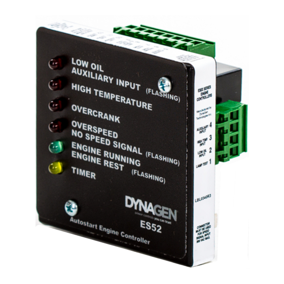
DynaGen ES52 Installation And User Manual
Auto start engine controller
Hide thumbs
Also See for ES52:
- Installation and user manual (25 pages) ,
- Installation manual (3 pages)

Related Manuals for DynaGen ES52


Summary of Contents for DynaGen ES52
- Page 1 ES52 Auto Start Engine Controller Installation and User Manual for the ES52 Auto Start Engine Controller. Full Version File: ES52 Rev 2_6_4.doc November, 2006...
- Page 2 LIMITED WARRANTY POLICY: DynaGen Technologies Inc. hereafter known as the Seller warrants articles sold hereunder to be free from defects in material and workmanship. These express warranties are the sole warranties of the Seller and any other warranties, expressed, implied in law, or implied in fact, are hereby specifically excluded.
-
Page 3: Table Of Contents
Selecting the Maximum Number of Crank Tries Warm Up LED INDICATIONS TROUBLESHOOTING GUIDELINES TECHNICAL NOTES ON FREQUENTLY ASKED QUESTIONS Diode Connections for Using Auto/Off/Test Switch Controller Memory Clear Time Step Down Transformer Use with Inverter Systems Operating & Installation Manual for the ES52 Engine Controller... -
Page 4: Introduction
Ours came to be one of the smallest controllers available, with the best value per dollar-cost, backed by an Industry Leading 5 Year Warranty. The ES52 maintains backward compatibility to the extent that it can replace similar products without substantial rewiring. Functionally, however, it is loaded with unique features: •... -
Page 5: Specifications
Close to +Battery to test LED’s Actual unit weight: 0.67 lb (0.30kg) Shipping weight: 1 lb (0.45kg) Unit dimensions: 3.302” x 3.342” x 1.8” Shipping dimensions: 4” (10.16cm) x 4” (10.16cm) x 3” (7.62cm) Operating & Installation Manual for the ES52 Engine Controller... -
Page 6: Wiring Installation Guidelines
Start/Stop connection 10Amps Fuel Solenoid/Pilot Relay 300mA Timer Output 13 ⇒ 18 300mA Annunciation Outputs 300mA Warm Up Output 300mA Annunciator Common Ground Only (DO NOT use this as main ground connection) Operating & Installation Manual for the ES52 Engine Controller... -
Page 7: Wiring Guidelines
WIRING GUIDELINES DO NOT use wire smaller than 18 AWG. The connections supplying DC power to the ES52 panel should preferably run directly from the battery posts with no splices or other connections except a 25Amp fuse connecting the positive line directly to the +Battery terminal. -
Page 8: Terminal Descriptions
Warm Up Output provides 300mA maximum. Warm Up Output activates after the controller has been running for 2 Minutes and 10 Seconds. Common ground - For Annunciation Outputs only. DO NOT USE AS MAIN GROUND TO CONTROLLER UNIT. Operating & Installation Manual for the ES52 Engine Controller... -
Page 9: General Wiring Diagram
General Wiring Diagram ATTENTION All ES52 Controllers come with 12VDC Relays for 12V systems. For 24V systems replace with 24VDC Relays. STARTER AUTO/OFF/TEST OR STARTER SWITCH SOLENOID FUEL SOLENOID TEST AND / OR REMOTE START IGNITION CONTACTS DIODE AUTO TIMER RELAY... - Page 10 ES52 Outline Dimensions TIMER FUEL START STOP RSC 2 RSC 1 AUTO (+Vbat) GROUND CRANK 3.342” 0.385” 0.486” 0.836” 1.186” 1.536” 1.886” 2.236” 2.886” Operating & Installation Manual for the ES52 Engine Controller...
-
Page 11: Adjustments And Setup Procedures
3 crank tries) immediately after the Engine Running LED illuminates (Engine starts). During this period the Oil Input is bypassed (ignored). Pots are shown below as they appear on the rear of the ES52 series units 1. Crank Disconnect 2. -
Page 12: Selecting The Engine Speed Range
If the Oil Pressure Switch does not work or the wire fails to make the connection, the engine will be prevented from starting and the ES52 will assume a ‘wait and see’ mode (indicated by a steady Low Oil and flashing Engine Running LED). - Page 13 If the Engine has been previously running and more than 5 Minutes of rest has elapsed. If Dip Switch 6 is set to the OFF position, the ES52 does not provide Oil verification. The ES52 goes immediately into cranking, it will then check for a Low Oil Failure condition after the Oil Bypass period has elapsed.
- Page 14 Step - 7 (Crank Disconnect Calibration) and Step 8 (Over Speed Calibration). • Smart Choke and Slow Timer functions are disabled. • Upon completion, reset Dip Switches 1, 2 and 3 to give desired crank tries. Operating & Installation Manual for the ES52 Engine Controller...
- Page 15 Note: If unit is configured for Generator Output, there may not be enough residual voltage during cranking. The following values are minimal recommended voltages for speed signal: 20Hz - .075V (75mV) 60Hz - .6V (600mV) 4500Hz - .8V (800 mV) Operating & Installation Manual for the ES52 Engine Controller...
-
Page 16: Selecting The Maximum Number Of Crank Tries
4 - 256 Sec 10: Warm Up A Warm Up timer is provided on all ES52 series Engine controllers. Terminal # 19 is the Warm Up timer output. This output energizes 2 Minutes after the Engine running LED turns ON (Speed above Crank Disconnect setting). -
Page 17: Led Indications
Installed). Engine will Crank when Oil Switch verifies. Over Speed and Over Crank LED's Invalid speed range – flash alternately Check Dip Switches 4 and 5 Crank Disconnect set too high TROUBLESHOOTING GUIDELINES Operating & Installation Manual for the ES52 Engine Controller... - Page 18 Generator output lines connected to the speed signal output. cable. If the neutral from the Generator output is not grounded, attach it to ground at Generator. Operating & Installation Manual for the ES52 Engine Controller...
-
Page 19: Technical Notes On Frequently Asked Questions
2. Controller Memory Clear Time The ES52 needs 10 Seconds for its memory to clear. When the power to the controller is turned OFF and then back ON again without waiting to clear the memory, a Loss of Speed will be indicated by the ES52 because the controller remains in Run mode and senses that the generator has stopped. - Page 20 The two wires from the Secondary of the transformer are connected to the two wires of the speed sensing terminals on the ES52 controller. The Step Down transformer acts to reduce the false speed signal on the line to a level that the Engine controller will not recognize as the Engine running.
- Page 21 CALIBRATED TIMER: _________ CR REST: _________ CR DISCONNECT: _________ OVERSPEED: _________ CRANK TRIES: _________ Operating & Installation Manual for the ES52 Engine Controller...
Need help?
Do you have a question about the ES52 and is the answer not in the manual?
Questions and answers