Table of Contents

Related Manuals for DynaGen RA400


Summary of Contents for DynaGen RA400
- Page 1 RA400 DynaGen Remote Annunciator For use with the GSC400 and TG410. Installation and User Manual – Revision 2.0 Full Version File : MAN-0081R2.0, RA400 User Manual.doc, October 2015 Thank You For Purchasing This DynaGen Product...
- Page 2 Authorization (RMA) number issued by DynaGen. RMA forms are available by contacting DynaGen Technical Support through the contact methods listed below. Limited Warranty The RA400 Remote Annunciator carries a one year warranty. For more information refer to the standard terms and conditions of sale at http://www.dynagen.ca. Support For up to date manuals and other support see http://www.dynagen.ca/support.
- Page 3 Weight 0.68 Kg (1.5 Lb) * Three LEDs Indicators are on in standby: “Communication Status”, “Not In Auto”, and “System Ready”. The RA400 maintains communication. There is no sleep mode for the RA400. User Manual for the RA400 Remote Annunciator...
-
Page 4: Table Of Contents
RA400 Mounting Dimensions ..............7 RA400 Terminals ....................9 RA400 Installation Guide ................15 2.5.1 Main RS485 Cable from Controller to RA400 ........15 2.5.2 Controller Connections ................16 Mount the 8 x 8 x 4” Pull Box ..............17 2.5.3... -
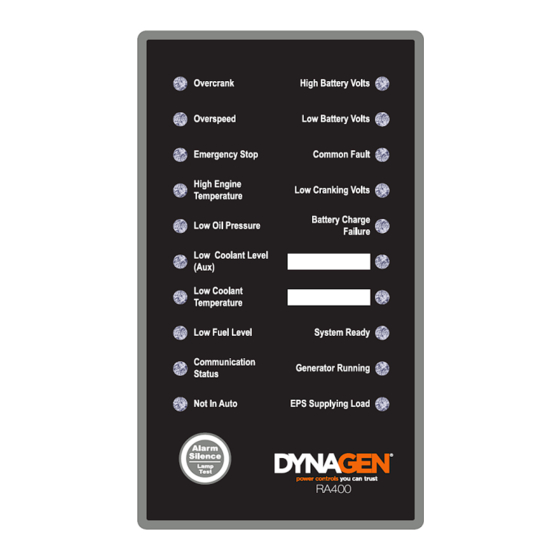
Page 5: Ra400 Remote Annunciator
It has 20 LED indicators to allow personnel to monitor the controller from a remote location. The RA400 can either act as a master or a slave. When set as a master the RA400 can also copy the controller information to up to three slave RA400 units. -
Page 6: Ra400 Series Installation And Wiring
When the RA400 is set as a master do not connector other modbus devices to addresses 2, 3, and 4 if harm can occur to personel via these devices. The RA400 uses these addresses automatically for it’s copy feature. Unexpected behaviour may occur. -
Page 7: Gsc400 Firmware Version
OFF or AUTO mode. For GSC400 firmware version 2.00 the default Modbus BAUD rate is set to 57600. This will have to be changed to 9600 (RA400 default) or 19200 as these are the only two BAUD rates the RA400 supports. - Page 8 8 of 41 Figure 2 – Size and placement of mounting holes (not to scale). User Manual for the RA400 Remote Annunciator...
-
Page 9: Ra400 Terminals
9 of 41 2.4 RA400 Terminals The RA400 can be powered from a 12VDC or 24VDC source. It will not operate below 6VDC and voltages above 30VDC may damage the unit. All connectors on the RA400 use plug in screw terminals which are included with the RA400. - Page 10 Pin 1 Pin 1 (+V) 6 – 30VDC, 3W Pin 1: Pwr Pin 2: Gnd Figure 3 – RA400 terminals as seen from the rear. Refer to following tables for more detailed information. User Manual for the RA400 Remote Annunciator...
- Page 11 Do not connect. There are two terminals provided to enable the installer to daisy chain multiple RA400 units together. If the RA400 is the last device on the communications bus, the two pins of J13 (the Modbus terminating resister jumper) must be shorted together (factory default).
- Page 12 19200. Default is OFF (9600). Switches 3 to 8 are the device ID of the GSC400 unit connected to the RA400 (if switch 1 is OFF) or the device ID of the RA400 (if switch 1 is ON). The device ID can range from 1 to 63. Default is address 1.
- Page 13 Figure 4 TG410 to RA400...
- Page 14 Figure 5 – GSC400 to RA400...
-
Page 15: Ra400 Installation Guide
Important: Pretest the controller and RA400 by connecting them directly to each side of the DynaGen harness (G3/G4) and confirm proper communications. This section will step you though the installation and setup of the RA400 to communicate with the DynaGen controller. While reading the following sections refer to Table 4 below for the required and optional parts and tools. -
Page 16: Controller Connections
2. If the GSC400 is not the last device on the Modbus network cut the resistor from the harness. 3. If you are not powering the RA400 from the battery wrap the extra power and ground wires on the harness in electrical tape to prevent accidental shorting. -
Page 17: Mount The 8 X 8 X 4" Pull Box
It does not matter which one but all three wires have to be on the same connector. 2. If the RA400 is not the last device on the Modbus network remove the jumper from J13. 3. Connect the RA400 EARTH wire – located on the three pin screw terminal, J14 –... -
Page 18: Gsc400/Tg410 Front Panel Configuration
Set the BAUD rate in the GSC400: Advanced Menu>Set Modbus>Baud Rate or TG410: Communications > Modbus > Baud Rate. 2. Modbus Device ID – The RA400 can support slave address in the range of 1 (default) to 63 except addresses 2 to 4 which are reserved for slave RA400 units. -
Page 19: Ra400 Configuration
With the RA400 in master mode, it will send requests to the controller. The RA400 will then turn on or off its indicators and buzzer as required. It will also send the data to addresses 2, 3, and 4 for the RA400 slaves to use. - Page 20 20 of 41 RA400 Slave Mode 1. Set switch 1 of SW2 to the ON position to set RA400 as slave. 2. Set switch 2 of SW2 to either the OFF position for 9600BPS or to the ON position for 19200BPS.
-
Page 21: Ra400 Operation
If the voltage powering the RA400 drops below 6V the microcontroller on the RA400 will reset but the LED drivers which control the LEDs may not. To the user it would appear that the RA400 is operational when it is in fact not. -
Page 22: Ra400 Led Status Indicators
RA400 units should respond within two to three seconds of a change in controller status. If using a DynaLink device it could take up to 30 seconds for the RA400 units to update after a change in the controller status especially if a user is viewing data from the DynaLink device on a web browser. - Page 23 LEDs for 2 seconds. Note that the amber color is produced by a combination of the green and red LEDs. Table 6 lists the LED indicators on the RA400, their definition, and colors. Table 6 – Front Panel LED Indicators...
-
Page 24: Alarm (Buzzer) And Alarm Silence
To re-activate the alarm (assuming that the event that caused the alarm is still active) press and hold the “Alarm Silence” button for 3 seconds until a lamp test is performed. After the lamp test the alarm will sound. User Manual for the RA400 Remote Annunciator... -
Page 25: Digital Inputs 1 And 2
3.7 Digital Inputs 1 and 2 The digital inputs on the RA400 have the following functionality: Note: only a master RA400 unit has the following functionality. The digital inputs on slave RA400 units are ignored. If a local start was performed (Run button pressed on the controller) then the generator can only be shut down by triggering a System Disable command from the RA400. -
Page 26: Recommended Maintenance
Check for any overheating due to loose Check for any discoloration, melting or connections blistering of any wiring or connections Perform regular testing of annunciator Perform regular testing annunciator check proper operation. User Manual for the RA400 Remote Annunciator... -
Page 27: Upgrading Ra400 Firmware
DB9 serial cable. Follow the below steps to load new firmware on the RA400. You will need the HC08SPRG.exe program. It is recommended that once the software has been updated that the software revision be marked on the RA400 for future reference. - Page 28 To use CHDIR to change the current directory, type CHDIR and then one space and then the file directory enclosed in quotations. In the figure below the current directory was changed from “C:\Documents and Settings\wmanning” to “C:\Documents and Settings\wmanning\Desktop”. User Manual for the RA400 Remote Annunciator...
- Page 29 The “1” refers to the COM port of the computer where you obtained in step 3 above. b) The 9600 is the BAUD rate of the RA400. Ensure that switch 2 of the 8 position DIP switch SW2 on the RA400 (see Table 2 on page 12) is in the OFF position.
- Page 30 30 of 41 Figure 10 – Invalid command response 8. Power on the RA400. You will see the following info appear (numbers shown may not be the same). Figure 11 – Program part prompt. 9. Type “y” if you want to start programming or type “n” if you want to cancel.
- Page 31 31 of 41 10. The program will verify that the memory has been programmed properly. It should say OK next to “Memory verified”. If it does not, try programming again. Figure 13 – Programmer ok. User Manual for the RA400 Remote Annunciator...
-
Page 32: Appendix A Troubleshooting
Check that the voltage to the RA400 power inputs is 6V or above. Voltages between 4.5V and 6V may cause the computer on the RA400 to reset but not the drivers controlling the LED indicators. This has the effect of making the RA400 appear operational, when in fact it is not. - Page 33 Table 2 – RA400 DIP Switch on page 12 for the switch position meaning. (4) Check that the RA400 is set to a master. If you are using the DynaLink WS100/WS200 device on the same modbus network, then the RA400 must be set as a slave and refer to the DynaLink user manual for more information.
- Page 34 Faults, Common Warnings, and Common Events should all be selected in the Modbus box. The ones not selected will not be sent over modbus to the RA400. The purpose of the Modbus selection is to allow control over which event type to display locally and which type to send remotely over modbus.
-
Page 35: Appendix B Modbus Map
35 of 41 Appendix B Modbus Map These are the registers that the RA400 reads from the GSC400 and TG410. There are also the internal registers of the RA400 itself. The RA400 interprets the data given in its registers to determine how to control the lights and horn. - Page 36 If bit9 is set, Low Battery Volts Indicator is red. If bit9 is Battery Volts cleared read register 40007 to determine if indicator should Failure Indicator be amber or off. If bit 10 is set, High Battery Volts Indicator is red. If bit9 is Override User Manual for the RA400 Remote Annunciator...
- Page 37 21, or 23 Indicator is flashing green (preparing to Running start). Indicator 3. If register 40100 = 0x9C and register 40101 is not equal to 19, 20, 21, or 23 Indicator is green. User Manual for the RA400 Remote Annunciator...
-
Page 38: Appendix C Drawings / Specs
Appendix C Drawings / Specs The following pages contain various drawings that may be useful. - Page 39 Figure 14 – Hoffman 8x8x4Pull B...
- Page 40 Figure 15 – Page 1 of ACC0120 datasheet. Model number is LPL-18-12. Taken from http://www.jameco.com.
- Page 41 Figure 16 – Page 2 of ACC0120 datasheet. Taken from http://www.jameco.com.
Need help?
Do you have a question about the RA400 and is the answer not in the manual?
Questions and answers