
Related Manuals for DynaGen Tough Series


Summary of Contents for DynaGen Tough Series
- Page 1 TG410 User Manual Manual Revision: 1.3.0 Min. FW Revision: 1.40.14 Date Released: 05/11/2013 © 2013 DYNAGEN Technologies Inc...
-
Page 2: Table Of Contents
4.4.6 Auxiliary ................................31 Fault Monitor Example ................................. 32 Start on Low / High Example ................................. 33 Output on Low / High Example ................................. 34 4.4.7 Custom Sender Tables ................................35 4.5 Timers ........................... 36 © 2013 DYNAGEN Technologies Inc... - Page 3 ........................... 40 4.6.1 Generator Voltage ................................40 4.6.2 Generator Frequency ................................41 4.6.3 Generator Current ................................41 4.7 Communications ........................... 42 CAN Bus (J1939) 4.7.1 ................................42 MOD Bus (RS485) 4.7.2 ................................43 5 Troubleshooting © 2013 DYNAGEN Technologies Inc...
-
Page 4: Introduction
The TOUGH series controllers are designed to provide complete control, protection, AC metering, and engine instrumentation for both standard and electronic engines. The module is easily configured using either the front panel buttons or our DYNAGEN Configurator software. TOUGH series controllers are ideally suited for severe duty applications where reliability is critical such as mobile and stationary generators. -
Page 5: Specifications
Introduction Specifications The TOUGH Series controllers were rigorously tested to ensure durability, reliability and functionality. The following specifications are a brief summary of the standards to which the controller has been tested. For complete details on the testing performed please contact DYNAGEN. -
Page 6: Installation
6) If applicable, snap the RelayPak (RP100) to the back of the controller. Place one side of the RP100s tabs into the slot on the back of the controller and without pushing on the relays, snap the other tab into place. TOUGH Series Manual © 2013 DYNAGEN Technologies Inc... -
Page 7: Terminal Descriptions
Provides ground return for 2-wire sensors. J3-8 Sensor Input D Universal sensor input (0 - 750Ω, 0 - 7,500Ω, 0 - 5VDC, 4 - 20mA) See Universal Sensor section for more information. TOUGH Series Manual © 2013 DYNAGEN Technologies Inc... - Page 8 Connect to current transformer for Phase B of the generator. J5-3 Phase C Connect to current transformer for Phase C of the generator. J5-4 CT Common Connect to the commons of the current transformers. TOUGH Series Manual © 2013 DYNAGEN Technologies Inc...
-
Page 9: Typical Wiring Diagram
Installation Typical Wiring Diagram TOUGH Series Manual © 2013 DYNAGEN Technologies Inc... -
Page 10: Typical Wiring Diagram With Relay Pak
Installation Typical Wiring Diagram with Relay Pak TOUGH Series Manual © 2013 DYNAGEN Technologies Inc... -
Page 11: Wiring Considerations
Shown below is an example wiring diagram of a double pull single throw switch being use to activate the e-stop input and cut power to the fuel solenoid. In this configuration, the e-stop is activated when there is an open circuit to the switched input and inactive when the input detects +Battery voltage. TOUGH Series Manual © 2013 DYNAGEN Technologies Inc... -
Page 12: Universal Sensor
The following diagram shows the typical wiring of a voltage divider. The resistors values have been selected to allow the controller to read up to 36V from an external battery bank. 0-36V Wiring Example TOUGH Series Manual © 2013 DYNAGEN Technologies Inc... -
Page 13: Can Bus Wiring
Turning on the Auto Power ECM setting in the Communications -> CAN Bus (J1939) menu enables the fuel relay to be on when controller is in Auto mode. This way the ECM will be always be on except when in OFF mode. ECM Wiring TOUGH Series Manual © 2013 DYNAGEN Technologies Inc... -
Page 14: Modbus Wiring
1. Up to 450ft - 22AWG Distance (Power and Ground) 2. Up to 700ft - 20AWG 3. Up to 1125ft - 18AWG 4. Up to 1800ft - 16AWG 5. Up to 2800ft - 14AWG Communications Wiring TOUGH Series Manual © 2013 DYNAGEN Technologies Inc... -
Page 15: Current Transformers
3. The wires from the current transformers to the controller should be as short as possible. NOTE: If readings are unstable with the configuration shown below, attempt connecting the CT Common's to the negative terminal of the battery. Ensure the connecting wire is as short as possible. TOUGH Series Manual © 2013 DYNAGEN Technologies Inc... -
Page 16: Relaypak (Optional)
Relay Style Automotive Cube WARNING: You must use relays in the RelayPak that are suitable for the system voltage. Example: 12V relays in a 12V system and 24V relays in a 24V system. TOUGH Series Manual © 2013 DYNAGEN Technologies Inc... -
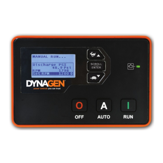
Page 17: Using The Controller
Used for moving around in the menu, changing a settings value, or changing the currently displayed parameter page. Generator LED Green = Engine running with no issues Amber = Engine running with warnings Red = Engine shutdown on failure TOUGH Series Manual © 2013 DYNAGEN Technologies Inc... -
Page 18: Modes, Starting And Stopping
When a certain command is sent to the controller over Modbus the engine will start. See the (TG410 only) Modbus Reference Manual for more information. WARNING: See the Using Cooldown Mode section for more information on how it affects starting and stopping. TOUGH Series Manual © 2013 DYNAGEN Technologies Inc... -
Page 19: Using Cooldown Mode
5. User presses RUN button on the front panel 6. Engine moves back into running mode and does not shutdown 7. Engine can now only be shutdown by the OFF button or Emergency Stop input TOUGH Series Manual © 2013 DYNAGEN Technologies Inc... -
Page 20: Settings
When enabled, allows user to start engine using the run button while in the OFF mode. When disabled the controller must be placed in AUTO mode before the run button can start the engine. TOUGH Series Manual © 2013 DYNAGEN Technologies Inc... -
Page 21: Switched Inputs
Stops the engine when momentarily active (Approximately 2 seconds). Configurable Warning 1 Configurable Controller displays a warning with configurable text when active. The DYNAGEN Configurator must be used to change the text. Configurable Warning 2 Configurable Controller displays a warning with configurable text when active. The DYNAGEN Configurator must be used to change the text. - Page 22 Open Input is active when neither +Battery or Ground is present at the terminal. NOTE: When running wires over long distances (100+), it is recommended to use +BATTERY as the trigger method. TOUGH Series Manual © 2013 DYNAGEN Technologies Inc...
-
Page 23: Voltage Select
Active Secondary RPM / 50Hz NOTE: If enabled, the TSC1 PGN will be broadcasted according to the selected speed. Otherwise only the warning and failure set points are affected by this function. TOUGH Series Manual © 2013 DYNAGEN Technologies Inc... -
Page 24: Configurable Inputs
Configurable Inputs These inputs are used to create custom warnings and failures. Using the DYNAGEN Configurator you can change the text that is displayed when the warning or failure occurs. If you select one of these inputs without changing the text it will default to 'Config Warn X' and 'Config Fail X.'... -
Page 25: Switched Outputs
Panel Speed Control section for more information. RPM Decrement Running Output is used to to trigger inputs on an ECM to control speed. See Front Panel Speed Control section for more information. TOUGH Series Manual © 2013 DYNAGEN Technologies Inc... - Page 26 Under Frequency Over Frequency AC Under Voltage AC Over Voltage Over Current ECM Communication Failure Configurable Failure 1 Configurable Failure 2 Auxiliary Sensor 1 Auxiliary Sensor 2 Auxiliary Sensor 3 Auxiliary Sensor 4 TOUGH Series Manual © 2013 DYNAGEN Technologies Inc...
-
Page 27: Group Outputs
-When any of the functions in a group is active (OR logic), the assigned switched output will be active. Group Functions Name Active Mode Description Group #1 Group Dependent Must be set from DYNAGEN Configurator software. Group #2 Group Dependent Must be set from DYNAGEN Configurator software. Group #3 Group Dependent Must be set from DYNAGEN Configurator software. -
Page 28: Sensors
Amount of time to bypass warnings and failures after engine has started. Setpoints -> Low Warning 0.1 ~ 99.0 PSI Reading at which a warning occurs. Setpoints -> Low Failure 0.1 ~ 99.0 PSI Reading at which a failure occurs. TOUGH Series Manual © 2013 DYNAGEN Technologies Inc... -
Page 29: Fuel Level
The Rated RPM when the Primary RPM / 60Hz is selected. RPM / Frequency Select section for more information. NOTE: When using J1939 or Genset Signal as a signal source, connections to the speed sensing terminals are not required. TOUGH Series Manual © 2013 DYNAGEN Technologies Inc... -
Page 30: Front Panel Speed Control
The Engine Speed display should update as the engine physically changes it speed to accommodate the speed request. NOTE: When using switched outputs for speed control, the Set RPM will display '---' instead of the set speed. TOUGH Series Manual © 2013 DYNAGEN Technologies Inc... -
Page 31: Battery Level
NOTE: When the engine is running, the battery voltage will equal the alternator charging voltage. The actual open- circuit battery voltage may be lower than displayed. Battery Recharge Sequence TOUGH Series Manual © 2013 DYNAGEN Technologies Inc... -
Page 32: Auxiliary
Reading at which a warning occurs. Dependent Setpoints -> High Failure Sender Table Reading at which a failure occurs. Dependent Refer to the sections below for more information on how these settings affect the auxiliary sensors. TOUGH Series Manual © 2013 DYNAGEN Technologies Inc... -
Page 33: Fault Monitor Example
275°F warning threshold so a warning is displayed. The engine continues to run because it does not reach the 350°F failure threshold. At 20 minutes run time the temperatures falls below the warning threshold and the warning disappears. TOUGH Series Manual © 2013 DYNAGEN Technologies Inc... -
Page 34: Start On Low / High Example
The chart above shows the connection between a battery bank and time. At approximately 80 minutes time the voltage falls below the 10.5V start threshold causing the engine to start. The engine runs for the 40 minutes active time regardless of the voltage reading and the shuts down. TOUGH Series Manual © 2013 DYNAGEN Technologies Inc... -
Page 35: Output On Low / High Example
325°F start threshold and the fan turns on. The fan continues to run as the temperature declines. When the temperature falls below the 200°F stop threshold the fan turns off. TOUGH Series Manual © 2013 DYNAGEN Technologies Inc... -
Page 36: Custom Sender Tables
Custom Sender Tables Custom Sensor Tables are created using the DYNAGEN Configurator when using a sensor that is not supported by DYNAGEN. The configurator has the ability to create these custom tables so that the controller can properly read the sensor data. -
Page 37: Timers
During this time the Warmup output turns off and the Cooldown output turns on. If another start command is received during cooldown, the controller will return to running mode. TOUGH Series Manual © 2013 DYNAGEN Technologies Inc... -
Page 38: Preheat Mode
WARNING: If the controller receives a command to start while in Cooldown, it will leave the Cooldown mode and go back to Running mode. TOUGH Series Manual © 2013 DYNAGEN Technologies Inc... -
Page 39: Exerciser
When configuring the Start Date and Hour, you must select a time in the future in which to run the initial exerciser sequence. After the initial sequence, the exerciser runs at an interval determined by 'Repeat Days.' Exerciser Sequence TOUGH Series Manual © 2013 DYNAGEN Technologies Inc... -
Page 40: Maintenance
To find out the amount of time until next maintenance, follow these menu steps: Main Menu -> Device Info. -> Maintenance Maintenance counter is disabled if '----' is displayed. A negative number indicates the amount of time since maintenance timer expired. TOUGH Series Manual © 2013 DYNAGEN Technologies Inc... -
Page 41: Ac Monitor
208.3V. Use the formula below to determine the scaling factor. 1. Scaling Factor = Multimeter Reading / Controller Reading 2. Scaling Factor = 208.4V / 206.3V 3. Scaling Factor = 1.010 TOUGH Series Manual © 2013 DYNAGEN Technologies Inc... -
Page 42: Generator Frequency
Reading at which a warning occurs. Percentages based off the Rated Amps value. Setpoints -> High Failure 1 ~ 125% Reading at which a failure occurs. Percentages based off the Rated Amps value. TOUGH Series Manual © 2013 DYNAGEN Technologies Inc... -
Page 43: Communications
Select the SPN conversion method. Version 2 Version 3 EMS2B Frequency Select Primary For Volvo EMS2B Engine Control Modules only. Secondary EMS2B Accelerator Pedal 40.0 ~ 60.0% For Volvo EMS2B Engine Control Modules only. TOUGH Series Manual © 2013 DYNAGEN Technologies Inc... -
Page 44: Mod Bus (Rs485)
The Modbus functionality on the controller provides the ability to interface to PLCs, SCADA and building management systems. For detailed information about the Modbus registers and their interpretations please use the Modbus Reference Manual. The manual can be found at www.dynagen.com/support. Name... -
Page 45: Troubleshooting
Reserved for future troubleshooting. Contacting DYNAGEN can be done by any of the methods below. Technical support is offered Monday - Friday, 8:00am - 4:00pm (EST). If you are unable to get a hold of one of our engineers, please leave a message and they will return your call as soon as possible.
Need help?
Do you have a question about the Tough Series and is the answer not in the manual?
Questions and answers