
Related Manuals for DynaGen TOUGH Series


Summary of Contents for DynaGen TOUGH Series
- Page 1 TG350 User Manual Manual Revision: 7.0.0 Min. FW Revision: 1.88.01 Date Released: 2019-09-25 © 2019 DynaGen Technologies Inc...
-
Page 2: Table Of Contents
..................................34 Sensors ....................................35 4.4.1 Engine Temperature ..................................35 4.4.2 Oil Pressure ..................................36 4.4.3 Fuel Level ..................................36 4.4.4 Engine Speed ..................................37 Front Panel Speed Control ..................................39 RPM Output ..................................40 © 2019 DynaGen Technologies Inc... - Page 3 RPM / Frequency Select ..................................61 Communications ....................................62 4.7.1 CAN Bus (J1939) ..................................62 Other Config ....................................62 4.8.1 Password ..................................62 4.8.2 Settings Name ..................................63 4.8.3 Process Control ..................................63 5 Troubleshooting © 2019 DynaGen Technologies Inc...
-
Page 4: User Guide
User Guide TOUGH Series Manual © 2019 DynaGen Technologies Inc... -
Page 5: Introduction
The module is easily configured using either the front panel buttons or our RapidCore Configuration software. TOUGH Series controllers are ideally suited for severe duty applications where reliability is critical such as mobile and stationary generators. - Page 6 Do not connect more than 600VAC to the controller for UL approved installations or 700VAC for locations where UL is not required. Communications SAE J1939 (Tier II, III, IV) External Sensor Power TG410 only: 5 VDC at a max load of 200mA TOUGH Series Manual © 2019 DynaGen Technologies Inc...
-
Page 7: Installation
6) If applicable, snap the RelayPak (RP100) to the back of the controller. Place one side of the RP100's tabs into the slot on the back of the controller and, without pushing on the relays, snap the other tab into place. TE Series Cutout (Not To Scale) TOUGH Series Manual © 2019 DynaGen Technologies Inc... -
Page 8: General Wiring Notes
Analog Inputs). The TOUGH Series contains a TVS to protect the I/O and internals from a transient on the main battery (the battery the controller is powered from). If you have I/O connected to other batteries or power supplies those I/O must contain their own voltage transient protection. - Page 9 Provides ground return for 2-wire sensors J3-8 Sensor Input D Universal sensor input (0 - 750Ohm, 0 - 7,500Ohm, 0 - 5 VDC, 4 - 20mA) See Universal Sensor section for more information. TOUGH Series Manual © 2019 DynaGen Technologies Inc...
- Page 10 Connect to Phase A of the generator J5-2 Phase B Connect to Phase B of the generator J5-3 Phase C Connect to Phase C of the generator J5-4 Neutral Connect to neutral of the generator TOUGH Series Manual © 2019 DynaGen Technologies Inc...
-
Page 11: Wiring Harnesses
Installation Wiring Harnesses TOUGH Series Manual © 2019 DynaGen Technologies Inc... -
Page 12: Typical Wiring Diagram
Installation Typical Wiring Diagram TOUGH Series Manual © 2019 DynaGen Technologies Inc... -
Page 13: Typical Wiring Diagram With Relaypak
Installation Typical Wiring Diagram with RelayPak TOUGH Series Manual © 2019 DynaGen Technologies Inc... -
Page 14: Wiring Considerations
Close +BAT. The trigger can be set to any of four options but Close +BAT gives the best immunity to noise. For runs over 20ft (6.1m) especially in noisy environments DYNAGEN recommends connecting the Start/Stop to an external relay. The relay needs to be located as close to the controller as possible. -
Page 15: Universal Sensor
NOTE: A TVS (i.e. varistor) is required if the battery is different than the battery the controller is powered from. The controller's TVS cannot protect the sensor input from transients in this case. TOUGH Series Manual © 2019 DynaGen Technologies Inc... -
Page 16: Can Bus Wiring
· Enable the Auto Power ECM setting in the Communications -> CAN Bus (J1939) menu will cause the fuel output to turn on in Auto mode and stay on. ECM Wiring TOUGH Series Manual © 2019 DynaGen Technologies Inc... - Page 17 Installation TOUGH Series Manual © 2019 DynaGen Technologies Inc...
-
Page 18: Relaypak (Optional)
Note:The relayPak can be used to sense DC voltages up to 39 VDC using one of the Auxiliary Sensor Inputs on the controller. The VM in RP100-VM refers to this voltage sensing capability. Refer to drawing DWG1552 under www.dynagen.ca/support. If this capability is used, the forth relay, Relay D, cannot be used. - Page 19 Installation TOUGH Series Manual © 2019 DynaGen Technologies Inc...
-
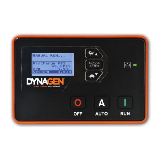
Page 20: Using The Controller
Used for moving around in the menu, changing a setting's value, or changing the currently displayed parameter page . Generator/Engine LED Green = Engine running with no issues Amber = Engine running with warnings Red = Engine shut down on failure TOUGH Series Manual © 2019 DynaGen Technologies Inc... -
Page 21: Modes, Starting And Stopping
ECM on an electronic engine so a diagnostic tool can obtain information from the ECM. WARNING: See the Using Cooldown Mode section for more information on how it affects starting and stopping. TOUGH Series Manual © 2019 DynaGen Technologies Inc... -
Page 22: Cranking Behaviour
7. Engine can now only be shut down by using the OFF button or Emergency Stop input Warnings Warnings are conditions that alert the user to possible issues. These get enabled/disabled when you enable/disable various settings in the controller. Notable warnings are given in the below table. TOUGH Series Manual © 2019 DynaGen Technologies Inc... -
Page 23: Failures
Event Log The below table lists all events, warnings, and failures than can appear in the controller's event history. The event history is accessed in the menu under "Events History". TOUGH Series Manual © 2019 DynaGen Technologies Inc... - Page 24 The controller has exited idle mode and has gone back into normal running. Speed Sensor 1 Event The controller has auto started due to a auxiliary sensor 1 "start on low" or "start on high" request. TOUGH Series Manual © 2019 DynaGen Technologies Inc...
- Page 25 Warning The oil pressure has fallen below the low oil pressure warning setpoint under Sensor > Oil Pressure. Pressure Low Fuel Warning The fuel level has fallen below the low fuel level warning setpoint under Sensors > Fuel Level. Level TOUGH Series Manual © 2019 DynaGen Technologies Inc...
- Page 26 The fuel level has fallen below the low fuel level failure setpoint under Sensors > Fuel Level. Level Failure The main starter battery (the battery the controller is powered from) voltage has fallen below the low Battery battery failure setpoint set under Sensors > Battery. TOUGH Series Manual © 2019 DynaGen Technologies Inc...
- Page 27 Engine Failure The controller is in the RUN mode and the engine speed has fallen below the crank disconnect Stall speed. The engine stall must be enabled under Timers > Engine Logic. TOUGH Series Manual © 2019 DynaGen Technologies Inc...
-
Page 28: Settings
When enabled, allows a user to start the engine using the run RUN from OFF Enable button while in the OFF mode. When disabled the controller must be placed in AUTO mode before the run button can start the engine. TOUGH Series Manual © 2019 DynaGen Technologies Inc... -
Page 29: Switched Inputs
"momentary start". It will not stop if the front panel run button was used to start the engine. Configurable Warning 1 Configurable Controller displays a warning or failure with configurable text* when active. In the case of the configurable failures a shutdown is also performed. TOUGH Series Manual © 2019 DynaGen Technologies Inc... - Page 30 Input is active when +Battery is present at the terminal. Close GND Input is active when Ground is present at the terminal Close +BAT/GND Input is active when either +Battery or Ground is present at the terminal. TOUGH Series Manual © 2019 DynaGen Technologies Inc...
- Page 31 Input is active when neither +Battery or Ground is present at the terminal. NOTE: When running wires over long distances (over 20ft / 6.1m), it is recommended to use +BATTERY as the trigger method. TOUGH Series Manual © 2019 DynaGen Technologies Inc...
-
Page 32: Configurable Inputs
Switched Disable Output F Event Functions Name Active Mode Description Fuel Cranking, Running Active during cranking and running to supply fuel to engine. Crank Cranking Active during cranking to start the engine. TOUGH Series Manual © 2019 DynaGen Technologies Inc... - Page 33 10s, the controller will shut down the engine on "Generator Disable Failure." Dummy Load Running Output is controlled by the dummy load feature. TOUGH Series Manual © 2019 DynaGen Technologies Inc...
- Page 34 When the controller encounters an unhandled exception or lockup (watchdog triggered) it will reset and enter the failure mode as an exception fault. *The name of this fault is configurable form the Configuration Software. TOUGH Series Manual © 2019 DynaGen Technologies Inc...
-
Page 35: Group Outputs
Note: The pull coil feature does not operate when the fuel output is activated by the Auto Power ECM feature or when requesting stored DTCs (DM2 codes). See the J1939 section for more information on these features. Pull Coil Wiring Example TOUGH Series Manual © 2019 DynaGen Technologies Inc... -
Page 36: Sensors
Reading at which a "High Engine Temp" warning occurs. Only applies if Warn (High 300°F (10 ~ Sensor Type has been set to a sender. Only monitored in the RUN Warning) 148.9 mode. TOUGH Series Manual © 2019 DynaGen Technologies Inc... -
Page 37: Oil Pressure
Close = Failure *These are preprogrammed into the controller and cannot be changed. - DAT R33-240 supports a Dacon fuel level sensor of the range 33 Ohms to (custom 180 Ohms sender)** TOUGH Series Manual © 2019 DynaGen Technologies Inc... -
Page 38: Engine Speed
Mag Pickup -- A magnetic pickup, alternator output, or the distributer signal can be used to sense speed. Must use J6 pins 7 and 8. If using a distributer a filter is often required. Contact DYNAGEN for more information on using a distributer signal. - Page 39 The speed is not monitored during delay-to-start or preheat as this provides some degree of protection against spurious signals due to noise. The fuel input is turned on at the start of preheat and often powers external equipment that can cause noise. TOUGH Series Manual © 2019 DynaGen Technologies Inc...
-
Page 40: Front Panel Speed Control
Disable, 10 ~ Ignore this setting. Refer to the J1939 reference manual for RPM/s Speed > RPM 300 RPM/s in information on this setting. 200 RPM Control 10 RPM/s increments Speed Control Instructions TOUGH Series Manual © 2019 DynaGen Technologies Inc... -
Page 41: Rpm Output
~ 24.0V Setpoints -> Disabled, Reading at which a warning occurs. Disabled High Warning 12.0 ~ 32.0V Setpoints -> Disabled, Reading at which a failure occurs. Disabled High Failure 12.0 ~ 32.0V TOUGH Series Manual © 2019 DynaGen Technologies Inc... - Page 42 NOTE: When the engine is running, the battery voltage will equal the alternator charging voltage. The actual open- circuit battery voltage may be lower than displayed. Battery Recharge Sequence TOUGH Series Manual © 2019 DynaGen Technologies Inc...
-
Page 43: Auxiliary Sensors
Mode Settings > Disable (Only applies if Func. Select is not set to Fault Monitor) The ----- Run Time amount of time to turn on the auxiliary switched output or run the TOUGH Series Manual © 2019 DynaGen Technologies Inc... - Page 44 Aux Sensor 2 Used by the Aux. Sensor 2 Output On Low or Output on High feature. Aux Sensor 3 Used by the Aux. Sensor 3 Output On Low or Output on High feature. TOUGH Series Manual © 2019 DynaGen Technologies Inc...
- Page 45 Turn off output when the drop below to turn on to rise above to sensor rises above a certain the output. turn off the output. value. TOUGH Series Manual © 2019 DynaGen Technologies Inc...
- Page 46 Warnings on the sensor. Monitor / Failures Do not perform any actions on the Fault sensor value. Just display the Monitor Display value to the user. (Disable all only warnings and failures) TOUGH Series Manual © 2019 DynaGen Technologies Inc...
-
Page 47: Fault Monitor Example
275°F warning threshold, activating the warning display. The engine will continue to run because it has not reached the 350°F failure threshold. At 20 minutes run time, the temperatures falls below the warning threshold and the warning disappears. TOUGH Series Manual © 2019 DynaGen Technologies Inc... -
Page 48: Start On Low Example
The chart above shows the connection between a battery bank and time. At approximately 80 minutes time, the voltage falls below the 10.5V start threshold causing the engine to start. The engine runs for the 40 minutes active time regardless of the voltage reading and then shuts down. TOUGH Series Manual © 2019 DynaGen Technologies Inc... -
Page 49: Output On High Example
325°F start threshold and the fan turns on. The fan continues to run as the temperature declines. When the temperature falls below the 200°F stop threshold, the fan turns off. TOUGH Series Manual © 2019 DynaGen Technologies Inc... -
Page 50: Custom Sensor Tables
4.4.7 Custom Sensor Tables are created using the RapidCore Configuration Software when using a sensor that is not supported by DYNAGEN. The configurator has the ability to create these custom tables, allowing the controller to properly read the sensor data. -
Page 51: Timers
If enabled, after the false restart delay and if the engine speed goes below the crank disconnect setting (1) disables oil Engine Stall Enable, Disable Disable pressure shutdown , and (2), after two seconds the controller will shutdown on an "engine stall" failure. TOUGH Series Manual © 2019 DynaGen Technologies Inc... -
Page 52: Preheat Mode
The false restart feature is used to monitor and recover from unsuccessful crank attempts where the speed did go above the crank disconnect and the controller is in the RUN mode. For example the engine might have stalled shortly after cranking. False Restart settings (under Timers > Engine Logic menu) TOUGH Series Manual © 2019 DynaGen Technologies Inc... -
Page 53: Off Button Function
WARNING: If the controller receives a command to start from the remote start or front panel run button while in Cooldown, it will leave the Cooldown mode and go back to Running mode. TOUGH Series Manual © 2019 DynaGen Technologies Inc... -
Page 54: Idle
"High Point" settings for this time exit the warm-up / idle. Settings increments Timers > Engine 1 to 180 (Warm-up Idle) Continue to idle when the temperature is below this Point Logic > Idle 32 F setting. Ignore the Debouce. Settings increments TOUGH Series Manual © 2019 DynaGen Technologies Inc... -
Page 55: Idle Inhibit
The controller will start after the pre-alarm countdown is finished. Schedule -> 1 ~ 28 days Number of days between each exerciser cycle. This setting is applied to all Repeat Days subsequent exerciser starts after the first start. Exerciser Sequence TOUGH Series Manual © 2019 DynaGen Technologies Inc... - Page 56 If the controller is in the OFF mode, if the emergency stop is activated, or if the start inhibit is active then the exerciser will not run. The event, "Bypass Exerciser", will be logged in the event log and the exerciser will run again at the next scheduled time as determined by the "Repeat Days" setting. TOUGH Series Manual © 2019 DynaGen Technologies Inc...
-
Page 57: Weekly Scheduler
To determine the amount of time until the next scheduled maintenance, follow these menu steps: Main Menu -> Device Info. -> Maintenance Maintenance counter is disabled if '----' is displayed. A negative number indicates the amount of time since maintenance timer expired. TOUGH Series Manual © 2019 DynaGen Technologies Inc... -
Page 58: Ac Monitor
50 ~ 99 % in 1 % Reading at which a warning occurs. 90 % Low Warn increments Setpoints > 50 ~ 99 % in 1 % Reading at which a failure occurs. 85 % Low Fail increments TOUGH Series Manual © 2019 DynaGen Technologies Inc... - Page 59 VAC but a calibrated multimeter gives 208.3 VAC. Use the formula below to determine the scaling factor. 1. Scaling Factor = Multimeter Reading / Controller Reading 2. Scaling Factor = 208.4 VAC / 206.3 VAC 3. Scaling Factor = 1.010 TOUGH Series Manual © 2019 DynaGen Technologies Inc...
-
Page 60: Ac Voltage Select
(Under-Frequency % in 1 % 90 % Warning) increments Setpoints > Low Fail Disable, 20 ~ 99 Reading at which a failure occurs. (Under-Frequency % in 1 % 85 % Failure) increments TOUGH Series Manual © 2019 DynaGen Technologies Inc... - Page 61 150 % in 1 % 110 % Warning) increments Setpoints > High Fail Disable, 101 ~ Reading at which a failure occurs. (Over-Frequency 150 % in 1 % 115 % Failure) increments TOUGH Series Manual © 2019 DynaGen Technologies Inc...
-
Page 62: Rpm / Frequency Select
Active Secondary RPM / 50Hz NOTE: If enabled, the J1939 TSC1 PGN will be broadcasted according to the selected speed. Otherwise only the warning and failure setpoints are affected by this function. TOUGH Series Manual © 2019 DynaGen Technologies Inc... -
Page 63: Communications
CAN Bus (J1939) 4.7.1 This page gives a very short overview of J1939 support (electronic engines). For detailed information about J1939 and all related settings please refer to the J1939 Reference Manual. The manual can be found at www.dynagen.com/support. Name Range... -
Page 64: Settings Name
The amount to increment or decrement the RPM when the sensed value increments is outside of the dead-band. This number does not represent an actual 19.0 RPM. A larger gain will generate a larger RPM change than a smaller TOUGH Series Manual © 2019 DynaGen Technologies Inc... - Page 65 Thresholds > Min 500 ~ 4000 RPM The fixed RPM that should be used when the level falls below the Low 1000 RPM (Low Limit in 1 RPM Edge. RPM) increments TOUGH Series Manual © 2019 DynaGen Technologies Inc...
-
Page 66: Troubleshooting
"Failure To Stop" failure. DYNAGEN can be contacted by any of the methods below. Technical support is offered Monday - Friday, 8:00am - 4:00pm (EST). If you are unable to contact one of our engineers, please leave a message and they will return your call as soon as possible.
Need help?
Do you have a question about the TOUGH Series and is the answer not in the manual?
Questions and answers