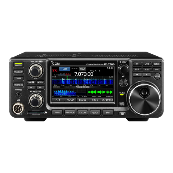
Icom IC-7300 Basic Manual
Hf/50 mhz transciever
Hide thumbs
Also See for IC-7300:
- Full manual (173 pages) ,
- Service manual (76 pages) ,
- Basic manual (72 pages)
Table of Contents
Advertisement
Advertisement
Table of Contents

Subscribe to Our Youtube Channel
Related Manuals for Icom IC-7300


Summary of Contents for Icom IC-7300
-
Page 2: Features
HF/50 MHz TRANSCEIVER state of the art technology and craftsmanship. With proper care, this product should provide you with years of trouble-free operation. We appreciate you making the IC-7300 your transceiver of choice, and hope you agree your IC-7300. READ ALL INSTRUCTIONS carefully completely before using the transceiver. - Page 3 Icom, Icom Inc. and the Icom logo are registered trademarks of Icom Incorporated (Japan) in Japan, the United States, the Microsoft, Windows and Windows Vista are registered trademarks of Microsoft Corporation in the United States and/or other countries.
-
Page 4: Dtouch Operation
D Touch operation D Touch screen precautions • The touch screen may not properly work when the operation is described as shown below. • topped object and so on, or touching the screen Touch hard may damage it. • sounds. pinch out cannot be performed on this touch screen. - Page 5 Detailed instruction the following manner. 1. Push MENU “ ” (Quotation marks): titles displayed on the screen. [ ] (brackets): Used to indicate keys. Push • 2. Touch [SET]. Routes to the set modes and setting screens Routes to the set mode, setting screen and the setting items are described in the following manner.
-
Page 6: Table Of Contents
............... i ........ 3-6 FEATURES..............i ................. i ..................i .....................ii Adjusting the transmit output power ....D Adjusting the transmit output power ..............ii ..............ii Meter display ..........3-10 ........iii D Meter display selection ......3-10 DTouch operation...........iii D Multi-function meter ......... - Page 7 11 OPTIONS ............11-1 ....................11-1 ............. 11-2 D Twin Peak Filter ........12 CONNECTOR INFORMATION ...... 12-1 ACC socket ............ 12-1 D Setting the decoder threshold level ..FM repeater operation........assignments..........12-2 ..Microphone connector........12-2 D External keypad ........
- Page 8 R WARNING! NEVER let metal, wire or other objects contact the inside of the transceiver, or make incorrect CAUTION: Use only Icom supplied or optional contact with connectors on the rear panel. This could cause an electric shock or damage the transceiver.
-
Page 9: Panel Description
PANEL DESCRIPTION Front panel This section describes the keys, controls and dials that you use to operate the IC-7300. Refer to the pages posted beside each key, control, or dial for details. q POWER KEY !1 FUNCTION KEY FUNCTION POWER (p. - Page 10 PANEL DESCRIPTION Front panel (Continued) @0 MEMO PAD KEY @8 TRANSMIT FREQUENCY CHECK KEY MPAD Sequentially calls up the contents in the Memo (p. 4-8) Pads, or saves the displayed contents into the Enables you to monitor the transmit frequency while Memo Pad.
-
Page 11: Rear Panel
ANTENNA CONNECTOR [ANT] (p. 2-2) !0 ALC INPUT JACK [ALC] (p. 2-2) Connects to the ALC output jack of a non-Icom r SOCKET [ACC] (p. 2-2) Connects to devices to control an external unit or to !1 TUNER CONTROL SOCKET [TUNER] (p. 2-2) control the transceiver. -
Page 12: Touch Panel Display
PANEL DESCRIPTION Touch panel display This section describes the icons, screens, dialogs, readouts and so on that are displayed on the IC-7300 screen. Refer to the pages posted beside each item for details. q TUNE ICON o M1~M8/T1~T8/OVF ICON (p. 7-1) Appears while tuning the antenna. - Page 13 PANEL DESCRIPTION Touch panel (Continued) !6 RIT ICON @3 BK-IN/F-BKIN/VOX INDICATOR (p. 4-1) (p. 4-12) Appears while the RIT function is ON. Appears while the Semi Break-in, Full Break-in or VOX function is ON. TX ICON (p. 4-8) @4 FREQUENCY READOUT (p. 3-3) Appears while the TX function is ON.
-
Page 14: D Multi-Function Menus
PANEL DESCRIPTION Touch panel (Continued) D Multi-function menus D FUNCTION screen Function Rotate name Selected value Push Touch the edge to Lights blue turn ON and OFF or orange when used FUNCTION screen Multi-function menu MULTI FUNCTION Open the Multi-function menu by pushing Open the FUNCTION screen by pushing EXIT (Multi-function control). -
Page 15: D Entering And Editing Characters
PANEL DESCRIPTION Keyboard entering and editing D Entering and editing characters You can enter and edit the items in the following table. Total Category Screen Selectable characters Information characters MENU MY CALL MEMORY MEMORY NAME KEYER MEMORY “*” (asterisk) has its unique use. RTTY MEMORY FUNCTION VOICE TX... -
Page 16: D Entering And Editing Example
PANEL DESCRIPTION Keypad entering and editing (Continued) D Entering and editing example Entering “DX spot 1” in the Memory channel 2 1. Open the MEMORY screen. Touch [ab]. » MEMORY MENU 2. Touch the memory channel 2 for 1 second. You can also open the QUICK MENU... -
Page 17: Installation And Connections
INSTALLATION AND CONNECTIONS Selecting a location Heat dissipation Select a location for the transceiver that allows • DO NOT place the transceiver against walls or put adequate air circulation, free from extreme heat, cold anything on top of the transceiver. This may block or vibrations, and other electromagnetic sources. -
Page 18: Rear Panel Connection
• Remote control operation using the optional tuner). RS-BA1. The AH-2b is connected to (Icom does not guarantee the performance of the the AH-4. PC, network device or network settings) [ACC] (accessory) soc et (p. 12-1) Connects control lines for external devices such as a TNC or a PC. -
Page 19: Connecting The Antenna Tuner
We recommend using Icom’s optional PS-126 periods of time. The transceiver becomes extremely hot. (DC 13.8 V 25 A) power supply. When connecting a non-Icom DC power cable, the transceiver needs • DC 13.8 V (Capacity At least 21 Amps) •... -
Page 20: Basic Operation
BASIC OPERATION MAIN DIAL • • Antenna • • Microphone* AF RF/SQL POWER POWER RF/SQL... - Page 21 BASIC OPERATION • • LSB-D • AM-D FM-D » MENU • •...
- Page 22 BASIC OPERATION • • MAIN DIAL Step function is You can set the MAIN DIAL • • • •...
- Page 23 BASIC OPERATION FUNCTION • • EXIT • function push EXIT MAIN DIAL MENU » • Entry exa ples • •(− • •(− • •(− • •(− • • •(−...
- Page 24 BASIC OPERATION • • • •(− − • − • Entry exa ples • • − •(− − • MENU »...
- Page 25 BASIC OPERATION Entry exa ples • • MENU » • • • • • • • • • Rotate Push Rotate Push • – Rotate MAIN DIAL • MULTI • Push...
- Page 26 BASIC OPERATION – Rotate Push • – •...
- Page 27 BASIC OPERATION • – • •...
- Page 28 BASIC OPERATION TRANSMIT RF/SQL • TRANSMIT • gain • le el Push • RF/SQL TRANSMIT • • • Lights red RF/SQL You can change the RF/SQL Rotate MENU » Push • MAIN DIAL TRANSMIT • SPEECH • • MENU »...
- Page 29 BASIC OPERATION MULTI TRANSMIT • MULTI • • • TRANSMIT •...
- Page 30 BASIC OPERATION r t e U and U data • • • r t e NOTE 3-11...
-
Page 31: Receiving And Transmitting
RECEIVING AND TRANSMITTING RIT function The preamps amplify received signals in the receiver The RIT (Receive Increment Tuning) function front end to improve the signal-to-noise ratio and compensates for differences in frequencies of other sensitivity. A preamp is used when receiving weak stations. -
Page 32: Agc Function Control
RECEIVING AND TRANSMITTING AGC function control The AGC (Automatic Gain Control) controls receiver gain to produce a constant audio output level, even You can set the preset AGC time constant to the when the received signal strength varies greatly. desired value. 1. - Page 33 RECEIVING AND TRANSMITTING electronically narrows the IF passband width by shifting the IF frequency to slightly outside of the IF You can narrow the IF passband width by rotating both TWIN PBT the opposite direction from each other. You can see the nearby signal using the Spectrum Scope (Section 5).
- Page 34 RECEIVING AND TRANSMITTING mode, and you can select them on the FILTER screen. FIL 1 3.0 kH ) 50H to 500H (50 H ) FIL 2 2.4 kH ) 600H to 3.6kH (100 H ) narrow (FIL 3). FIL 3 1.8 kH ) FIL 1 1.2 kH ) 1.
- Page 35 RECEIVING AND TRANSMITTING • SHARP The Noise blanker eliminates pulse-type noise such This selection is to emphasi e the passband width of as the noise from car ignitions. The Noise blanker cannot be used in the FM mode. out and it gives you better audio quality. Push •...
-
Page 36: Notch Filter
RECEIVING AND TRANSMITTING Notch Filter The Noise Reduction function reduces random noise The IC-7300 has Auto Notch and Manual Notch components and enhances desired signals that are functions. buried in noise. The Noise Reduction function uses the DSP circuit. modes. - Page 37 RECEIVING AND TRANSMITTING VOX function The VOX (Voice-Operated Transmission) function switches between transmit and receive with your voice. This function enables a hands-free operation. VOX GAIN (Default 50 ) items. Adjust the transmit receive switching threshold level • VOX GAIN to between 0 and 100 for VOX operation.
-
Page 38: Tx Function
RECEIVING AND TRANSMITTING Monitor function ∂TX function The ∂TX function shifts the transmit frequency up to The Monitor function enables you to monitor your kH without shifting the receive frequency. transmit audio. Use this function to check the voice characteristics while adjusting transmit audio 1. - Page 39 RECEIVING AND TRANSMITTING The Speech Compressor increases the average RF output power, improving readability at the receiving station. This function compresses the transmitter audio input to increase the average audio output level. The function is effective for long-distance communication, or when propagation conditions are poor. 10.
- Page 40 RECEIVING AND TRANSMITTING Split fre uency operation Split frequency operation enables you to transmit There are 2 ways to use the Split frequency operation. and receive on different frequencies in the same or • Use the Quick Split function different bands. •...
- Page 41 RECEIVING AND TRANSMITTING Operating CW D Setting the CW pitch control The Split Lock function is convenient for changing only the transmit frequency but not changing the You can set the received CW audio pitch and the CW receive frequency. side tone to suit your preference without changing the operating frequency.
- Page 42 RECEIVING AND TRANSMITTING Operating CW (Continued) You can set the key speed of the internal electric keyer. automatically switch between transmit and receive 1. Select the CW mode. and Full break-in modes. 2. Display the Multi-function menu. TIP The key type is set to “Paddle” by default. You can select the keyer type on the CW-KEY SET screen.
- Page 43 RECEIVING AND TRANSMITTING Operating CW The CW-R (CW Reverse) mode reverses the receive signals. automatically transmits while keying down, and then Use when interfering signals are near the desired immediately returns to receive after keying up. signal and you want to use the CW-R to reduce interference.
- Page 44 RECEIVING AND TRANSMITTING Operating CW (Continued) D Electronic Keyer function You can set the Memory Keyer function settings, paddle polarity settings, and so on of the Electronic Keyer. 1. Open the KEYER screen in the CW mode. You can edit the Keyer memories. »...
- Page 45 RECEIVING AND TRANSMITTING With the built-in RTTY decoder and the contents set in the RTTY TX memory, you can operate the basic If you are receiving an RTTY signal but cannot decode RTTY operation without using an external device. correctly, try in the RTTY-R (reverse) mode. If you are using PSK software, refer to the software manual.
- Page 46 RECEIVING AND TRANSMITTING Operating RTTY (FSK) (Continued) Open the RTTY DECODE screen in the RTTY mode. Adjusting the RTTY decoder threshold level prevents characters been decoded by noise, even though you » DECODE MENU have not received an RTTY signal. 1.
-
Page 47: Fm Repeater Operation
RECEIVING AND TRANSMITTING FM repeater operation D Setting the repeater tone fre uency A repeater receives your radio’s signals and simultaneously retransmits them on a different Some repeaters require a subaudible tone to be frequency to provide a greater communication range. accessed. -
Page 48: Scope Operation
» SCOPE MENU The IC-7300 has two spectrum scope modes. One is the Center mode, and another one is the Fixed mode. You can also turn the Waterfall display ON or OFF. In addition, you can select a Mini scope screen to save screen space. -
Page 49: D Center Mode
SCOPE OPERATION Spectrum scope screen (Continue) D Center mode D Fixed mode Displays signals around the operating frequency within the selected span. The operating frequency is The selected frequency band activity can easily be always displayed in the center of the screen. observed this mode. -
Page 50: D Touch Screen Operation
SCOPE OPERATION Audio scope screen Spectrum scope screen (Continue) D Touch screen operation This audio scope enables you to display the received When you touch the FFT scope one or the waterfall signal’s frequency component on the FFT scope, and one in the SPECTRUM SCOPE screen, the area its waveform components on the Oscilloscope. -
Page 51: Using An Sd Card
When reading or writing data is impossible, the card’s lifetime has ended. In that case, use a new one. important data onto your PC. (p. 8-7) • Icom will not be responsible for any damage caused by data corruption of a card. Card orientation... - Page 52 USING AN SD CARD Unmounting an SD card Formatting an SD card Before using an SD card with the transceiver, be sure Before you remove a card when the transceiver is ON, to format all SD cards with the built-in Format function. be sure to electrically unmount it, as shown below.
-
Page 53: Antenna Tuner Operation
ANTENNA TUNER OPERATION About the internal antenna tuner Internal antenna tuner operation 1. Push to turn ON the internal antenna The internal automatic antenna tuner automatically TUNER tuner. matches the transceiver to the antenna within the • “TUNE” is displayed when the tuner is ON. 2. -
Page 54: Set Mode
SET MODE Set mode description You can use the Set mode to set infrequently changed values or function settings. TIP The Set mode is constructed in a tree structure. You may go to the next tree level, or go back a level, depending on the selected item. -
Page 55: Tone Control
SET MODE Tone Control SSB RX HPF/LPF (Default SSB TX Bass SSB TX Treble If this item is set, the “SSB RX Bass” and “SSB RX Sets the bass or treble level of the receive audio. SSB TBW (WIDE) SSB RX Bass SSB TBW (MID) SSB RX Treble Sets the bass or treble level of the receive audio. -
Page 56: Function
SET MODE Function Beep Le el Time-Out Timer (CI-V) (Default OFF) Sets the beep output level. Sets the Time-out Timer for CI-V operation. This setting is valid only transmitting initiated by a TRANSMIT beep sounds. CI-V command or pushing Select “OFF” for no time limit. Beep Le el Limit (Default ON) Quic SPLIT... - Page 57 SET MODE Function (Continued) S-Le el SPEECH (Default ON) Screen Capture [POWER] SW (Default OFF) Turns the S-meter level announcement ON or OFF. Assigns the Screen Capture function to POWER MODE SPEECH (Default OFF) Screen Capture File Type (Default PNG) Turns the operating mode announcement ON or OFF.
-
Page 58: Connectors
SET MODE Connectors ACC/USB Output Select (Default AF) CI-V Baud Rate (Default Auto) Selects the signal output from [ACC] and [USB]. Selects the CI-V data transfer rate. When “Auto” is selected, the baud rate is automatically set according to the data rate of the ACC/USB AF Output Le el connected controller. - Page 59 SET MODE Connectors (Continued) Display RTTY Decode Baud Rate LCD Bac light Selects the data transfer rate (Baud rate) of decoded Sets the LCD backlight brightness. RTTY signals. Display Type (Default A) USB SEND (Default OFF) Sets the display type to A or B. You can control transmit and receive from the PC through the USB port.
-
Page 60: Time Set
SET MODE Time Set Others Date Version Touch Screen Calibration Time Touch to adjust the touch screen. Sets the current time. See section 14 of the Full Manual for details. (The time is displayed in the 24 hour format.) Partial Reset UTC Offset Resets operating settings to their default values (VFO Sets the UTC offset time. -
Page 61: Maintenance
MAINTENANCE Resetting D Partial reset Occasionally, erroneous information may be displayed. This may be caused by static electricity or 1. Open the RESET screen. by other factors. MENU » SET Others Reset If this problem occurs, turn OFF the transceiver. After 2. -
Page 62: Specifications
SPECIFICATIONS D General • Frequency coverage (unit MH ) Receiver 0.030000~ 74.800000* Transmitter 1.800000~ 01. 3.500000~ 03. 5.255000~ 05.405000* 7.000000~ 07.300000* 10.100000~ 10.150000* 14.000000~ 14.350000* 18.068000~ 18.168000* 21.000000~ 21.450000* 24.8 0000~ 24. 0000* 28.000000~ 2 .700000* 50.000000~ 54.000000* 70.000000~ 70.500000* Some frequency ranges are not guaranteed. -
Page 63: D Receiver
SPECIFICATIONS D Recei er • Receive system Direct sampling superheterodyne • Intermediate frequency 36 kH • Sensitivity (Filter SOFT) SSB CW (at 10 dB S N) 70 MH band* Depending on the transceiver version. AM (at 10 dB S N) FM (at 12 dB SINAD) •... -
Page 64: Options
OPTIONS Options AH-2b AH-4 IC-PW1/IC-PW1EURO ANTENNA TUNER LINEAR AMPLIFIER ANTENNA ELEMENT AH-740 HM-36 PS-126 CT-17 AUTOMATIC MICROPHONE DC POWER SUPPLY V CONVERTER TUNING ANTENNA • • NVIS KIT SM-50 SM-30 SP-23 SP-34 DESKTOP MICROPHONE DESKTOP MICROPHONE EXTERNAL SPEAKER EXTERNAL SPEAKER •... - Page 65 OPTIONS Mounting the MB-118 MOUNTING BRACKET NOTE • • 11-2...
-
Page 66: Connector Information
CONNECTORS set screen. (p. 8-5) (Example) ACC socket 100 mV rms is at the 50 (default) setting. To a non-Icom You can change the output level in the “ACC USB AF e SEND Output Level” item on the CONNECTORS set screen. -
Page 67: Acc Socket
CONNECTORS set screen. (p. 8-5) PINy Front panel » SET Connectors External Keypad MENU External keypad • VOICE ON • KEYER ON • RTTY The External keypad is not supplied by Icom. (User supplied) 12-2... -
Page 68: Ext-Sp Jack
13.8 V DC 15 through the RWARNING NEVER reverse the REMOTE ac Rear panel ie REMOTE Used for computer control and transceive operation connecting a PC to [REMOTE]. 15 V DC Cable (RS-232C type) ct-17 IC-7300 mini-plug cable 12-3... -
Page 69: Index
INDEX Numbers and symbols Editing 1 H step Fine Tuning function ..........3-3 1 4 Tuning function ..............3-4 Characters ................. 1-7 5 MH frequency band operation ..........3-11 Example................1-8 Keyboard ................1-7 ∂TX function................4-8 Electronic Keyer function............4-14 ∂TX monitor function ............ - Page 70 INDEX Saving data onto the SD card..........6-1 Main dial, using............... 3-3 Maintenance ................-1 Scope operation ..............5-1 Manual Notch function............4-6 SD card................... 6-1 Formatting................6-2 Manual tuning ................. 7-1 Marker ..................5-2 Saving data................ 6-1 MB-118, mounting ..............11-2 Inserting ................
-
Page 71: About Ce
ABOUT CE INSTALLATION NOTES For amateur base station installations it is recommended In all cases any possible risk depends on the transmitter that the forward clearance in front of the antenna array is being activated for long periods. (actual recommendation calculated relative to the EIRP (Effective Isotropic Radiated Power). - Page 72 Country o ntended Country o ntended Country o A-72 2H-1EX Printed in apan 1-1-32 Kamiminami, Hirano-ku, Osaka 547-0003, apan 2016 Icom Inc.
Need help?
Do you have a question about the IC-7300 and is the answer not in the manual?
Questions and answers