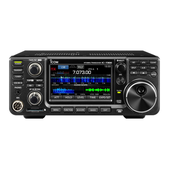
Icom IC-7300 Adjustment Procedure
Hf/50 mhz transceiver
Hide thumbs
Also See for IC-7300:
- Full manual (173 pages) ,
- Service manual (76 pages) ,
- Basic manual (72 pages)
Advertisement
Advertisement
Table of Contents

Subscribe to Our Youtube Channel
Summary of Contents for Icom IC-7300
- Page 1 ADJUSTMENT PROCEDURE HF/50 MHz TRANSCEIVER S-15218XZ-C1 March 2016...
- Page 2 SECTION 4 ADJUSTMENT PROCEDURE 4-1 PREPARATION M REQUIRED EQUIPMENTS EQUIPMENT GRADE AND RANGE EQUIPMENT GRADE AND RANGE 50 Ω and 100 Ω/120 W Dummy Loads Impedance: Modified 3.5 mm (1/8 inch) monaural plug Shunt plug (See the illustration below.) Attenuator Attenuation: 50 dB/120 W Measuring range:...
- Page 3 FRONT Preset TX/ID TUNER/REF 4-1 PREPARATION (continued) Sub adjustment menu [MIC] M ENTERING THE ADJUSTMENT MODE 1) Connect the shunt plug to [REMOTE] (See page 5-1). 2) While holding down the [MENU] and [FUNCTION] keys, turn ON the transceiver power. 3) The main adjustment menu appears.
- Page 4 4-3 TX IDLING CURRENT ADJUSTMENTS • Touch [TX/ID] on the main adjustment menu screen. NOTE: The transceiver automatically transmits when a TX adjustment item is selected. ADJUSTMENT ITEM TRANSCEIVER'S CONDITION OPERATION VALUE PREPARATION 1) Connect the power meter (or dummy load) –...
- Page 5 4-4 TX POWER ADJUSTMENTS • Touch [TX/ID] on the main adjustment menu screen. NOTE: The transceiver automatically transmits when a TX adjustment item is selected. ADJUST ADJUSTMENT ITEM TRANSCEIVER'S CONDITION OPERATION VALUE POINT TX POWER & 1 • Display: “TX POWER SET” 1) Connect the AG with the millivoltmeter –...
- Page 6 4-4 TX POWER ADJUSTMENTS (continued) ADJUST ADJUSTMENT ITEM TRANSCEIVER'S CONDITION OPERATION VALUE POINT TX POWER & 18 • Display: "TX Total 70M Gain" – 25 W POWER METER SETTING • Transmit (automatic) (A beep sounds, and (70 MHz band) then another beeps sound 0.5 sec.
- Page 7 4-6 FREQUENCY ADJUSTMENTS • Touch [TUNER/REF] on the main adjustment menu screen. NOTE: The transceiver automatically transmits when a TX adjustment item is selected. ADJUSTMENT ITEM TRANSCEIVER'S CONDITION OPERATION VALUE PREPARATION 1) Connect the power meter to the antenna Touch [TUNER/REF]. connector.


Need help?
Do you have a question about the IC-7300 and is the answer not in the manual?
Questions and answers