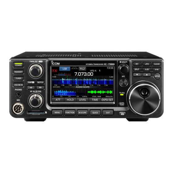
Icom IC-7300 Manual
Hide thumbs
Also See for IC-7300:
- Full manual (173 pages) ,
- Service manual (76 pages) ,
- Basic manual (72 pages)
Advertisement
Quick Links
Advertisement

Subscribe to Our Youtube Channel
Related Manuals for Icom IC-7300


Summary of Contents for Icom IC-7300
- Page 1 ETTING THE MOST FROM YOUR RANSCEIVER , AB1OC EMMERER , 2017 ANUARY...
- Page 2 Topics • Its mostly about the receiver… • Transmitter/amplifier operation tips and tricks • Common operating scenarios Not to Scale...
- Page 3 Its Mostly About The Receiver Multi-Function Screen Commonly Available Controls Passband Tuning Operating (DSP) Filter & Mode Receive IF Shift Preamp/ Notch ”Roofing” Adjusts *’ed Incremental Attenuator Filters* Filter* Items Tuning Noise Reduction/ Blanker* Access Audio Pan Adapter/ CW Auto Function Gain Gain...
- Page 4 Its Mostly About The Receiver - Some Terms Bandwidth, Dynamic Range and Signal to Noise Ratio • Bandwidth – tools to limit your receiver so it “hears” only what you want to hear and to protect it from overload • Mostly about filters •...
- Page 5 Its Mostly About The Receiver Basic Receiver Elements (Single Conversion Analog) “Roofing” Filter (Pre) Bandpass Filter “DSP” AGC Loop(s) Filtering • Filters limit Bandwidth to reject unwanted signals, preventing them from adversely effecting performance • The Automatic Gain Control (AGC) System attempts to maximize Dynamic Range within Weak Signal Receiver Stages •...
- Page 6 Its Mostly About The Receiver Basic Receiver Elements (Direct Sampling ex. IC-7300) Digital Osc. RF (Pre-) Bandpass Amplifier Filter Digital Proc. (FPGA) AGC Loop, IP+ • Most filtering, all noise reduction and signal detection steps are performed digitally • AGC System must maximize A/D converter resolution for the desired signal •...
- Page 7 Its Mostly About The Receiver Controls to Optimize Weak Signals Adjusts *’ed Passband Tuning Items (DSP) Filter & IF Shift Preamp/ Attenuator Noise Reduction/ Blanker* Access Function Screen Gain (AGC Controls) • Filters Limit Bandwidth and optimize adjacent signal rejection •...
- Page 8 Minimize Noise BW/Interference: • Roofing Filters – typically “fixed” BW filters applied before IF stages • DSP filters – Digital Signal Processing after IF stages • Both are realized in Digital Processor of the IC-7300 Not to Scale IF Shift Example...
- Page 9 Its Mostly About The Receiver CW Reverse Sideband (CW-R) Freq. Freq. Standard CW CW-R Sideband Sideband Reversing CW Sideband to Improve Adjacent Signal Rejection Not to Scale...
- Page 10 Its Mostly About The Receiver Dynamic Range – Its About Optimal Gain Control Digital Osc. RF (Pre) Bandpass Amplifier Filter Digital Proc. (FPGA) AGC Loop, IP+ Too Little Base Gain Too Much Base Gain Optimal Base Gain (Preamp Helps) 11..1 (Preamp Off/Attn.) 11..1 11..1...
- Page 11 Its Mostly About The Receiver Dynamic Range – Its About Optimal Gain Control 11..1 Digital Osc. RF (Pre) Bandpass Amplifier Filter Digital Proc. (FPGA) AGC Loop, IP+ 00..0 • Goal is to add enough gain to amplify the desired signal for maximum converter resolution •...
- Page 12 Its Mostly About The Receiver Noise Reduction – Digital Magic to Reduce Noise Adaptive digital filter estimates random noise characteristics to cancel Detects pulse oriented noise and eliminates using short- Use these sparingly, especially duration blanking if desired signal is weak...
- Page 13 Its Mostly About The Receiver Starting Point for Receiver settings • Set preamplifier/attenuator so that the noise floor is close to “S0” on your signal meter • Set RF gain at Max. and AGC speed setting matched to mode: • Fast for CW mode •...
- Page 14 Its Mostly About The Receiver Pulling in and Cleaning Up a Weak Signal 1. Narrow your filters to reduce noise and reject interference 2. Shift your IF to reject adjacent signal interference and match passband to desired signal characteristics 3. Try CW-R if a strong adjacent signal is interfering 4.
- Page 15 Its Mostly About The Receiver Receive Incremental Adjusts *’ed Other Important Features Tuning Items Notch Filters* • Auto Notch Filter – the “Tuner Up’er Control” CW Auto • Can protect your ears, especially when wearing headphones Tune • Don’t use it with CW or Digital Modes •...
- Page 16 VFO/ Its Mostly About The Receiver Memory Mode Other Important Features Recent Frequency Memory • CW “Side Tone” setting – a personal choice • Higher frequencies enable faster speeds for folks with good hearing • 600 – 800 Hz range is a good place to start •...
- Page 17 RANSMITTER IPS AND RICKS...
-
Page 18: Your Transmitter
Your Transmitter Understanding Your Meters • S0: Receive Signal Strength • Po: Output Power • SWR: Displays Antenna’s SWR when in Tx • ALC: Automatic Level Control Limits • COMP: Speech Compression Level • VD: Final Amp Drain Voltage • ID: Final Amp Drain Current •... - Page 19 Your Transmitter Multi-Function Screen Important Controls Functions Operating Split Adjusts Tx Pwr, Incremental Manual Mode Controls Mic Gain Tuning Auto Tuner VOX / CW Break-in Access Function Tuning Screen...
- Page 20 Your Transmitter Adjusting Microphone Gain, Compression, Tx Bandwidth Mic Gain Knob or Multi-Function Knob • Turn off compression, turn power down/amp off, connect a Dummy Load • Set Tx bandwidth for SSB phone consistent with band conditions • 2.4 KHz if operating in crowded band conditions •...
- Page 21 Your Transmitter Other Important Adjustments Break-In/ Adjust Tx Audio and VOX for Microphone and Operating Environment • Tx Audio Equalization is very important • Basic Tx Treble and Bass adjustments are adequate • Choice in setups – warm audio for rag chewing and crisp, easy to copy audio for DX’ing and Contesting •...
- Page 22 Your Transmitter Tuners, Antenna Switches, Power and Monitoring • Antenna Tuners – use sparingly • They have loss and are generally not needed if SWR is ≤ 1.5:1 • Most built-in tuners will handle a 2:1 mismatch • If you must tune up on the air, do it at low power and off the operating frequency of others •...
- Page 23 Your Transmitter Using an Amplifier Usually 30 – 50W Drive Will Create Full Output – AVOID OVERDRIVING! • Best to configure amplifier to start up in Standby mode – check out tune and SWR in “barefoot” mode and adjust Tx power on your rig •...
- Page 24 OMMON PERATING CENARIOS...
-
Page 25: Split Operation
Split Operation • Station Transmits on one Frequency and listens at a different place • ”Listen Frequency” can be a single one or a range • Most will listen “Up” but can be “Down” as well • Typical split scenarios: •... - Page 26 Your Transmitter Working Split Enables Split Incremental Mode Tuning Swaps or Matches Tx and Rx VFO 1. Tune to DX Transmit Frequency Listen on 2. Enable split mode & Adjust Tuning 3. Set Tx and Rx VFOs to same frequency Secondary (Tx) VFO 4.
- Page 27 Busting Pileups • Make sure you hear the other station before beginning; try to pattern them before calling; double check that your rig is in split if need before calling • Its mostly about timing • Drop in your callsign at just the right time •...
-
Page 28: Digital Mode Operation
Digital Mode Operation • Use Digital Mode setting or disconnect microphone/disable audio processing • Set your audio drive just below the point where you see ALC meter deflection • Be mindful of power levels when operating in “shared passband” modes like PSK or JT65 •... - Page 29 Getting To Know You, …. Reading The Manual, Reading The Fine Manual For Your Rig….
- Page 30 N1FD.org TECH NIGHT Jan 10, 20117 Transmitter Monitoring WHY ?..I set the radio to punch out 800 watts and the ham across the valley can hear me ! Yep, and the next door neighbors’ radio hears you loud & clear D.
- Page 31 N1FD.org TECH NIGHT Jan 10, 20117 Transmitter Monitoring • WHY ? I set the radio to punch out 800 watts and the ham across the valley can hear me ! Technician License Test: Section T7B (2014): Common transmitter and receiver problems: symptoms of overload and overdrive;...
- Page 32 Transmitter Monitoring Devices in the Radio Shack Radio Stand alone analog/digital power/SWR meter meters Dedicated Station Monitor Oscilloscope with RF sampler D. Michaels N1RF Jan 10, 2017 Transmitter Monitoring...
- Page 33 Transmitter Monitoring Devices in the Radio Shack D. Michaels N1RF Jan 10, 2017 Transmitter Monitoring...
- Page 34 Transmitter Monitoring Devices Is Your Power Meter Accurate ? Oscilloscope with RF sampler Oscilloscopes can provide an “adequate” calibration of the power setting on your radio and stand alone power meters D. Michaels N1RF Jan 10, 2017 Transmitter Monitoring...
- Page 35 Transmitter Monitoring Devices Is Your Power Meter Accurate ? RF Sampler RF Sampler RF Sampler takes a very small percentage of the Tx power that can safely be sent to the ocilloscope D. Michaels N1RF Jan 10, 2017 Transmitter Monitoring...
- Page 36 Transmitter Monitoring Devices Is Your Power Meter Accurate ? Resistor Divider RF Sampler Current Transformer Typical sampling power RF Sampler values are: 1:100 = -20 dB 1: 1000 = -30 dB 1:10,000 = -40 dB 1:100,000 = -50 dB D. Michaels N1RF Jan 10, 2017 Transmitter Monitoring...
- Page 37 Design for a Current Transformer RF Sampler Simplification: To maintain impedance balance and reduce required N for a given dB + Rser = 50 Rload Rsa = 50 Io = sqrt(Tx power / 50) Rsh = 100 * N * sqrt (Psa/Po) Is = Io/N N = Rsh * sqrt (Po/Psa)/100 I1 = Is * (Rser + Rsa)/sum(Rj)
- Page 38 Design for Current Transformer RF Sampler D. Michaels N1RF Jan 10, 2017 Transmitter Monitoring...
- Page 39 Testing the -50 dB RF Sampler Scope: Chn 1 = 56 v p-p Chn 2 = 0.180 v p-p dB = -49.8 D. Michaels N1RF Jan 10, 2017 Transmitter Monitoring...
- Page 40 Digging Deeper with a Full Station Monitor • Frequency Counter • Power (avg, peak, PEP) • SWR • Waveforms (CW, SSB AM, FM, Digital) Keying envelope AM Modulation distortion SSB 2 Tone Test Trapezoid Linearity D. Michaels N1RF Jan 10, 2017 Transmitter Monitoring...
- Page 41 Digging Deeper with a Full Station Monitor D. Michaels N1RF Jan 10, 2017 Transmitter Monitoring...
- Page 42 Digging Deeper with a Full Station Monitor D. Michaels N1RF Jan 10, 2017 Transmitter Monitoring...
- Page 43 Bibliography 1.Oscilloscopes • Oscilloscope Fundamentals Tektronix: circuitslab.case.edu/manuals/Oscilloscope_Fundamentals_-_Tektronix.pdf • ARRL’s book Oscilloscopes for Radio Amateurs by Paul Danzer, N1II 2. RF Samplers • Measuring Transmitter Power with the Oscilloscope: http://preciserf.com/wp- content/uploads/2012/04/Appnote-4-Power-tests1.pdf • Build a Quality RF Sampler by Don Jackson, W5QN: www.collinsradio.org/wp-content/.../Build-a- Quality-RF-Power-Sampler-Jackson.pdf 3.
Need help?
Do you have a question about the IC-7300 and is the answer not in the manual?
Questions and answers