
Summary of Contents for Eagle Tree Systems Vector
- Page 1 USER GUIDE Vector Multirotor/Fixed Wing Flight Controller + OSD User Guide April, 2016 Version 2.8 Software Version 11.78+...
-
Page 2: Table Of Contents
3.4 ..Current Sensor Maximum Continuous Current, and Load Testing ................15 3.5 ..Vector Wiring ....................................16 3.5.1 Vector Video Harness + Connecting your Video Camera and Transmitter ................16 3.5.2 Providing power to your Video Transmitter and Camera ......................18 3.5.3 Vector Audio Harness and Audio Connections ............................. - Page 3 5.2 ..Transmitter Channel Mixing ..............................31 5.3 ..Configuring with the Windows Software ..........................32 5.4 ..Configuring the Vector via Stick Menus or InfoPanel ....................33 5.4.1 Teaching the Vector about SPPM or S.BUS™ Channel Mappings ....................34 5.4.2 Navigating the Stick Menus ....................................
- Page 4 Configuring Failsafe Detection ................................53 5.12.2 Configuring RTH/Safety Mode ................................55 5.12.3 Configuring Maximum Altitude and Maximum Distance ......................56 5.13 ... The Vector’s LED Indicator ............................... 56 5.14 ... Configuring the OSD ..................................57 5.14.1 Adjusting the Display ....................................57 5.14.2 Setting Display Units (English or Metric) ............................
- Page 5 7.5.1 Home Altitude Mode ......................................80 7.5.2 Other Advanced RTH Settings ..................................81 7.6 ..Acoustic Variometer ..................................81 7.7 ..Vector Calibration ..................................82 7.7.1 Electrical Calibration ......................................83 7.7.2 Altimeter Calibration ......................................83 7.7.3 Pitot Airspeed Calibration ....................................84 7.8 ..
-
Page 6: Safety
The Vector is intended to be used exclusively for recreational purposes in model aircraft. Using the Vector for other purposes is not supported. Further, using the Vector in situations where its use or failure could result in loss of life, bodily injury or property damage is expressly prohibited. -
Page 7: Overview
Never operate your model within 5 miles of airports, without permission from the airport! Never operate the Vector in a situation where it may get wet, such as on a rainy day. Do not change wiring in your model when any power is applied. -
Page 8: Packing List
Tricopter, Quadcopter, and Hexacopter multirotors Recommended Airframes: the Vector is not recommended for large or heavy airframes, due to no or limited testing on these types of models at this time. Examples: giant scale fixed wing models, gas or nitro models, turbines, or multirotors larger than 650mm are not recommended. -
Page 9: How To Get Help And Request New Features
2.5 Installing the Software, and Updating the Firmware To configure your Vector with the software, or to update the Vector firmware, you will need to install our software on a compatible device. -
Page 10: Updating Your Vector Firmware
2.5.3 Updating your Vector Firmware Even if you will be configuring the Vector using the stick menus, it’s a good idea to keep your Vector firmware updated, in case we add a feature or resolve an issue that is relevant to your airframe. Our latest software always has the latest Vector firmware included with it. -
Page 11: Glossary Of Terms Used In The Manual
Attitude – The orientation of the model with respect to the horizon. 2D Mode – A mode where the model is brought to a level attitude (level flight and level wings) by the Vector when the control stick is centered. - Page 12 Configuration Gestures – A series of toggles of the Mode Switch. The number of times you toggle the switch determines which configuration step is performed. PSU - Power Supply Unit. This refers to the 5V and 12V switching regulators built into the Vector current sensor.
-
Page 13: Connecting The Vector
3.1.1 Backup Power If you want the Vector to use a redundant power supply for safety, the middle pin of the RSSI/5V Backup connection can be used to supply backup power to the Vector. Normally the Vector is powered by 5V from the Current Sensor/PSU, but the Vector will take power from the backup connection whenever the voltage at this pin is approximately 0.5V higher than the voltage coming from the Current Sensor/PSU. -
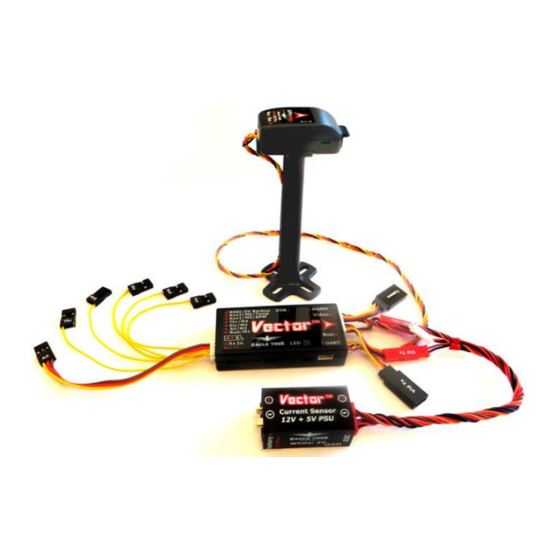
Page 14: Vector Gps/Mag, Current Sensor/Psu, And Accessory Connections
For example, if the backup power is connected to the BEC of your ESC (via your receiver), and that is supplying 5.0V, the Vector will use the PSU power unless the PSU voltage drops below 4.5V. Likewise, if your BEC is providing 6.0V to the backup power port, the backup power port will always be powering the Vector unless the... -
Page 15: Vector Current Sensor/Psu Power Output
3.3 Vector Current Sensor/PSU Power Output The Vector’s high efficiency and low noise PSU accepts up to 6S voltage input, and provides filtered 5V and up to 12V output at 1A max per channel*. It's perfect for powering most FPV gear, and can also power your receiver on multirotors (when NO servos are being powered by the RX!), eliminating the need for an external BEC. -
Page 16: Vector Wiring
3.5.1 Vector Video Harness + Connecting your Video Camera and Transmitter The Vector's innovative video harness makes it easy to connect your 5V or 12V cameras and transmitters without keeping an electrician on standby. The figure below shows a typical hookup, with a 12V camera, 12V... - Page 17 “C” on the video harness. Inside the Vector, the red wire of the camera power connector “D” is internally connected to the red wire of the camera connector “F”, and the red wire of transmitter power connector “E” is internally connected to the red wire of transmitter connector “C”.
-
Page 18: Providing Power To Your Video Transmitter And Camera
5V tap if the Alerter is used. The affected voltage regulator may shut off if this is exceeded, which can cause the Vector to turn off during flight if the 5V regulator is affected, as well as shutting off the... -
Page 19: Vector Audio Harness And Audio Connections
GoPro works correctly. 3.5.3 Vector Audio Harness and Audio Connections If you do not want to hear Vector voice alerts or the acoustic variometer, it is not necessary to use the audio harness, so this step can be skipped. -
Page 20: Vector Receiver Harness
The Vector does not power your receiver or servos. You will need to power your receiver and servos as you would in a non-Vector model, such as with a stand-alone BEC, a BEC built into your ESC, or a separate battery pack. -
Page 21: Receiver Connection Harness Load Capacity (Fixed Wing Only)
If you are not using all the servo output connections on your Vector, a male to male servo wire (with the signal line cut!) can be connected between a free servo channel on the Vector, and a free channel on your receiver. - Page 22 USER GUIDE In this case, it’s important that you make sure you never arm your multirotor when the main ESC power connector is disconnected from the Current Sensor/PSU. Or, you can address this issue in some other ways: a) remove/disconnect the red wire from the “Ail” connector, so that power will not pass from your receiver to the ESCs when using the 5V tap to power your receiver.
-
Page 23: Connecting Receiver And Servos/Escs To The Vector
3.5.7 Connecting Receiver and Servos/ESCs to the Vector First, connect your ESC or servo wires to the Vector output ports without powering the Vector, to make sure they reach the desired Vector mounting location. Then disconnect them before proceeding to the configuration section. - Page 24 USER GUIDE The chart below shows typical receiver and servo/ESC connections for these airframe types. * The Receiver Output and Vector Rx Harness sections do not apply to SPPM or S.BUS™ receiver modes. Airframe Vector Receiver Output* Vector Rx Vector Output...
- Page 25 USER GUIDE Airframe Vector Receiver Output* Vector Rx Vector Output Servo/ESC Airframe Type Harness* Connection at Model V-Tail with Ailerons 2/3 position (cont.) Mode Switch Gain Knob or Submode switch Tricopter Tricopter Rudder/yaw Rudder/M1 Motor 1 ESC Norm or Rev...
-
Page 26: Connecting You Receiver's Rssi Output (If Available)
If you wish to display the receiver’s signal strength (RSSI), and your receiver supports this feature, you will need to connect the top (signal) pin of the “RSSI/5V Backup” connection of the Vector to your receiver’s RSSI output. The Vector’s RSSI input is fully buffered with a high impedance op amp. -
Page 27: Mounting The Vector And Accessories
4.1 Mounting the Vector 4.1.1 Mounting Location and Orientation Mount the Vector flat and level with the label facing toward the sky and the red arrow on the Vector case facing toward the nose of your model (the direction of forward travel). -
Page 28: Mounting The Gps/Mag Sensor
RTH! The GPS/MAG must be flat relative to the Vector. Mounting errors of even a few degrees in the pitch or roll axes can introduce noticeable error in the compass heading, leading to toilet bowl behavior in multirotors... -
Page 29: The Gps Stand And Clip
USER GUIDE The Vector automatically computes the magnetic declination (compass error) at your location, so it is normally not necessary to rotate the GPS/MAG to correct for compass error. The GPS/MAG has an LED, which can be viewed from the back of the unit (see the arrow on the label). -
Page 30: Controlling The Vector
The Mode switch (a 2 or 3 position switch on your radio that is mapped to the “Mod” input of the receiver harness, or mapped to an SPPM or S.BUS™ channel) is the primary way that you communicate with the Vector via your radio. -
Page 31: The Gain Knob
Configuring your radio to work with the Vector Teaching the Vector about your radio’s serial channel mapping, if you are using the SPPM or S.BUS™ receiver protocol Selecting the airframe type (airframe type must be confirmed with Mode switch after rebooting – see section 5.6) -
Page 32: Configuring With The Windows Software
1) Read through the rest of the manual to understand the setup steps, warnings, etc. 2) Run the software with the Vector connected to USB. You will also need to have your transmitter bound to your receiver and functioning correctly. -
Page 33: Configuring The Vector Via Stick Menus Or Infopanel
Controller Settings tab, by clicking on that tab, or clicking the “Configure Multirotor Settings” button. 9) With the Vector and the model perfectly level, record flat level mounting by clicking the “Record Flat Level” button. Now, the artificial horizon (AHI) display should show level, and should closely follow your movements as you pitch and roll the model. -
Page 34: Teaching The Vector About Sppm Or S.bus™ Channel Mappings
5.4.1 Teaching the Vector about SPPM or S.BUS™ Channel Mappings If you are using SPPM or S.BUS™, the Vector must first learn how your sticks, switches and other outputs are mapped to the serial output channels, so that you can control the menus for further configuration. - Page 35 Mode without moving any switches. Flip Flaps Sw if Used/Tog If you wish to use a flap switch or knob with the Vector, change its position and toggle Mode. If you are not going to use it, just toggle Mode without moving any switches.
-
Page 36: Navigating The Stick Menus
5.4.4 Accessing Menus during Flight For advanced users, the Vector’s menu system can be configured so that menus are accessible in-flight. To do this, invoke menu mode, go to the “Radio Control Settings” menu, and set “Disable Menus When Flying?” to “No.”... -
Page 37: Selecting The Airframe Type
5.6 Accepting the Airframe Type For safety, when you select the airframe type via the Stick Menus, the Vector will ask you to confirm the newly selected airframe type on the next boot-up after you change it, but only after USB is disconnected. The Vector’s outputs will not be turned on until you OK the airframe type. -
Page 38: Running The Receiver Analysis Wizard
Mode During the wizard, the Vector shuts off the Vector throttle output channel for fixed wing, and all the Vector output channels for multirotors. You have 10 seconds to turn off your transmitter. Make sure your Turn Transmitter off now... -
Page 39: Configuring Auxiliary Receiver Inputs And Servo Outputs
If your transmitter does the mixing for these auxiliary channels, the appropriate inputs need to be mapped as described above. If you want the Vector to do the mixing, do not select an input corresponding to that channel. Instead, just select the correct output as described below. - Page 40 USER GUIDE Inputs/Outputs” menu item. Then, select the “Aux 1 Output Channel Functon” or “Aux 2 Output Channel Functon” menu item and set the output as desired. If you find that you need to have an output channel reversed, do that with the “Reverse Aux 1 Output?” or “Reverse Aux 2 Output?”...
-
Page 41: Flight Modes, And Configuring The Mode/Submode Switches
5.10.1 Flight Mode Description The Vector supports a wide variety of flight modes, which you can select in flight using your Mode switch, and optionally a Submode switch. The table below describes these modes, and also indicates whether the GPS (with a good 3D fix) and the magnetic compass are required. - Page 42 USER GUIDE Stabilization Turns off the stabilizer Cartesian Same as 2D Mode with Hold, except that the heading of the multirotor is remembered when you arm, and the stick always controls the multirotor as if it were yawed to that same heading.
-
Page 43: Control Stick Function In Multirotor Modes
The altitude hold's lock is reset every time the elevator stick is moved. Also, note that if the Vector detects stall-like conditions (severe roll), or the model is traveling at a ground speed (based on the GPS) that is less than the “Minimum Ground Speed” setting on the Safety Setup tab of the software, both altitude and heading hold will be temporarily disabled. -
Page 44: Programming The Optional Submode Switch
USER GUIDE designation in the table below. To configure the Mode switch positions, navigate to the “New Airframe Checklist”, and select the “Set up Mode/Submode Switches” menu item. Then, select the function of each of the up to 3 Mode switch positions. Your switch positions may be reversed from the illustration, depending on your radio settings. -
Page 45: Configuring The Flight Controller/Stabilizer
Confirming ESC endpoints are correctly programmed Setting idle throttle, and confirming motor order and rotation direction are correct Configuring low battery autoland Setting flat level mounting, which lets the Vector compensate for small mounting offsets Rezeroing the gyros 5.11.1 Setting Controller Gains 5.11.1.1... - Page 46 If a gain value is too low, the Vector will not push your control surface or motors hard enough to return to level quickly. For example, with a fixed wing plane in 2D Mode, if the roll gain is not high enough, the wings may not return to level quickly (or at all) when you release the sticks.
- Page 47 Check an RC forum to see if anyone has posted good Vector gain settings for your particular airframe. Don’t use gain settings for other controllers with the Vector! 5.11.1.4...
- Page 48 Note that the “Maximum Pitch” and “Maximum Roll” settings are not necessarily honored for fixed wing models. At low gain values, the control stick will overcome the Vector’s stabilization and exceed the specified maximum angles. 3D Direct Rate: When in 3D Heading Hold (direct rate) mode, each 3D Direct Rate setting controls the rotational rate of the model in the respective axis, in rotations per second (Hz), when the stick is fully deflected in the direction controlling that axis.
-
Page 49: Verifying Correct Control Surfaces Movement (Fixed Wing)
Verifying Correct Control Surfaces Movement (Fixed Wing) In addition to making sure that your radio sticks move the control surfaces in the correct direction, you also must ensure that the Vector’s stabilizer moves the surfaces in the right direction to keep the model in level flight. -
Page 50: Arming And Disarming Your Multirotor (Multirotor Only)
USER GUIDE 5.11.4 Arming and Disarming your Multirotor (Multirotor only) 5.11.4.1 Arm and Disarm Gestures The multirotor is armed by moving the throttle stick to the off position and holding the rudder stick in the rightmost position for 2 to 3 seconds, until the props spin continuously. For Mode 2 radios, this is done by simply holding the left (rudder/throttle) stick in the lower right-hand corner (the ARM corner) for approximately 1 second. -
Page 51: Setting Idle Throttle (Multirotor Only)
For tricopters, the motor rotation direction is aribitrary, but don’t forget to match the correct propeller orienation with the motor rotation direction! One way to test if your setup is correct is to use the motor tester built into the Vector. To do this, invoke menu mode, select the “Multirotor Configuration” menu, and select “Motor Tester”. -
Page 52: Configuring Low Battery Autoland (Multirotor Only)
Setting Flat Level Mounting Before flying, the Vector needs to correct for any controller mounting offsets that could affect level flight. To do this, place the model so that it is perfectly level (on a level counter or floor), invoke menu mode, and select “Record Flat Level Mounting”... -
Page 53: Configuring Return To Home And Other Safety Modes
The Return to Home feature (RTH), when configured properly, can return your model to the “home point” if your radio link is lost (in failsafe). Additionally, the Vector lets you program the maximum distance and maximum altitude that your model should never exceed. - Page 54 When you run the Receiver Analysis wizard, the Vector will detect the low trim failsafe position when you turn off your radio. Whenever the throttle is trimmed that low, the Vector will assume the receiver is in failsafe. And, the Vector will learn your normal minimum throttle during the wizard, when it asks you to set the throttle to the off position.
-
Page 55: Configuring Rth/Safety Mode
These options are available: Land: For fixed wing, the Vector will try to keep the wings level and shut the throttle off after failsafe is detected, resulting in a “crash landing” (not a good idea for stall-prone airframes!) For multirotors, the multi will descend immediately after failsafe is detected, at a controlled rate. -
Page 56: Configuring Maximum Altitude And Maximum Distance
The Vector’s OSD provides detailed information about Vector status, the present flight mode, and any errors that are detected. However, for Line of Sight flying, the LED can be used to determine the Vector’s status at a glance. Here are the meanings of the Vector LED Indicator blinks:... -
Page 57: Configuring The Osd
A Loiter flight mode is selected USB mode is active 5.14 Configuring the OSD The Vector’s built-in color OSD has many advanced features and display options. Even so, it can be easily configured to display basic information that is sufficient for most pilots. -
Page 58: Setting Display Units (English Or Metric)
Vector servo outputs. 5.14.4.2 Altitude, Speed and Distance Readouts Barometric Altitude: This displays the present barometric altitude of the model from the built in pressure sensor, which is zero referenced (set to zero) when the Vector is powered up. - Page 59 This readout is only meaningful if you are flying with a relatively constant amp draw. Receiver RSSI: This is the RSSI (Received Signal Strength Indicator) percentage, derived from the Vector’s RSSI input pin described earlier. Note: if the RSSI input was not correctly connected during the Receiver Analysis Wizard, the RSSI indicator will show a “?”.
-
Page 60: Advanced Numeric Readouts
5.14.5 Advanced Numeric Readouts The Vector has a wealth of parameters that can be configured for display, and, you can also customize the Vector to display numeric readouts on multiple screens, move the readouts around on the screen, and configure advanced features of the readouts, such as displaying “gauge” and “swatch” readouts. - Page 61 For example, if you fly your model so that your body is facing 15 degrees N, you would set this to 15. This results in the RADAR icon flying “up” on the Vector screen when you are flying the model in the direction you are facing.
-
Page 62: Setting Osd Alarms
(via the audio connection to your video transmitter). Setting up alarms for common conditions is quite easy with the Vector. Just navigate to the “Alarms/Alerts Setup” menu from the OSD Setup screen, and select the alarms you want. -
Page 63: Configuring And Calibrating The Magnetic Compass
Low Pack Voltage Alarm The alarm for pack voltage is set by specifying the per cell voltage that will trigger the alarm. The Vector automatically detects the cell count for your pack, so you can switch between packs of different cell counts, without needing to reset the alarm each time. -
Page 64: Calibrating The Compass
RED LED flashes. This spin should take about 10 seconds. 6) The Vector will analyze calibration for 5 to 10 seconds. Rarely, if calibration is inadequate, tumble calibration mode will start again, and the LED will turn solid GREEN again. Repeat steps 3-5 if this occurs. -
Page 65: Testing The Compass
Please refer to the latest EagleEyes online manual (found on the Support tab on our website) for instructions on configuring the EagleEyes with the Vector. When coupled with the Vector, the EagleEyes FPV ground station provides the following features, which can be configured and controlled directly from the Vector on-screen menus: ... -
Page 66: Configuring And Using The Alerter Buzzer/Lcd
Alerter buzzer to maximum volume when armed/flying. Mute Buzzer if USB or in menu – This option turns off the Alerter buzzer when the Vector is connected to USB, or is in menu mode ... -
Page 67: The Alerter Leds
This alarm can make it more likely that you can find your model after a crash, since it will sound after this number of minutes of idle time (as long as the Vector is powered and connected to the Alerter) even if your power system temporarily shuts off during a crash. - Page 68 USER GUIDE 5 Blinks, followed by LONG BLINK The Vector is not level enough to arm There is an issue with the signals coming from your 6 Blinks, followed by LONG BLINK receiver (some channels are not being received, the receiver is not powered, cables are loose, etc.)
-
Page 69: First Flights
6.1 Preflight Checklist The Vector includes an interactive preflight checklist, which lists some of the common things that you should check (or do) before flying. Of course, no generic list is complete, so this should only serve as a supplement to your normal checklist. -
Page 70: First Flight Recommendations
If this happens, the multirotor can suddenly climb very rapidly! Be prepared to switch out of altitude hold mode and land, if this condition occurs. Also, the Vector attempts to detect this condition and switch out of altitude hold mode after a few seconds, each time the condition occurs. -
Page 71: Fixed Wing Stalls
First fly your model with stabilization off (or with overall gain turned off with the gain knob) and adjust your radio trims for level flight. Land, and rerun the Receiver Analysis Wizard so that the Vector can learn about the new radio trim settings. ... -
Page 72: Rth Ground Testing
USER GUIDE If there are obstacles in the path between the model and home, RTH will not be able to avoid them. You are responsible for your model, even when RTH is engaged! If the wind speed is higher than the RTH speed of the model, determined by its settings, the model will NOT return home if flying into the wind. -
Page 73: Advanced Vector Setup And Calibration
Display on which Row: The Vector’s numeric readout display consists of 5 columns (from left to right) and 4 rows (from top to bottom), letting you display a total of 20 numeric readouts on each screen. Rows 1 and 2 are at the top of the OSD display, and rows 3 and 4 are at the bottom of the display. -
Page 74: Gauges And Swatches
OSD to switch to the screen containing this readout, when an alarm for it is triggered. Speak Readout if Alarm?: Setting this item to “Yes” will cause the readout to be spoken via the Vector’s audio output, when the alarm triggers. - Page 75 For the Motor Voltage readout, the values entered for thresholds need to be per-cell voltages (i.e., 4.2), rather than overall pack voltages. The Vector automatically detects the cell count for your pack, so you can switch between packs of different cell counts, without needing to reset the pack voltage swatch settings each time.
-
Page 76: The Advanced Graphics/Indicators Menu
7.2.2.1 Brushless RPM Sensor Setup Assuming the Aux1/M5/RPM Vector port is not being used to control a servo or motor output, you can connect a MODIFIED Eagle Tree “Brushless RPM Sensor” (P/N RPM-BRS-V2) to that port, and display and log RPM. -
Page 77: Waypoints
7.2.2.2 Brushless RPM Sensor Hookup and Configuration For correct RPM sensor readings, you need to let the Vector know the number of “poles” your brushless motor has. This setting is entered in the “Num Brushless Motor Poles” section of the Calibration and Sensor Setup menu. -
Page 78: Showing Waypoints On The Osd
If you choose to have data logging stop when the buffer is full, don’t forget to clear the logging buffer before each flight, from the Preflight menu. 7.4.2 Downloading, Viewing and Saving Logged Flight Information With the software, you can download flight information from the Vector, view the data, and save it for later retrieval. - Page 79 7.4.2.1 Downloading Data To download and view logged data, connect the Vector to USB, and select the “EagleEyes and Data Logging” tab under the ”EagleEyes, Data Logging and Flight Map” branch in the tree view, and click the “Download from Vector”...
-
Page 80: Additional Data Logging And Telemetry Features
USER GUIDE 7.4.2.6 Using Excel™ to View Data The log files are compatible with Excel ™ spreadsheet software, and other spreadsheet products supporting space delimited data files. To load a saved data file in Excel, click the Open option in Excel, and type “*.FDR” in the file name field. Then navigate to the location where you saved the .FDR file, and click on the file. -
Page 81: Other Advanced Rth Settings
7.5.2.3 Disabling PCM Glitch Detection In addition to checking to see if your receiver is in failsafe mode, as an additional layer of protection the Vector also monitors the health of the signals coming from your receiver. If the Vector sees receiver pulses that are out of spec (too long or too short), or if servo pulses stop altogether for a channel, RTH will be triggered. -
Page 82: Vector Calibration
The variometer is off when motor current is more than approximately 1.5 amps. 7.7 Vector Calibration The Vector is factory calibrated, and normally no further calibration is necessary. However, user calibration of some sensors can be performed. Calibration options are located on... -
Page 83: Electrical Calibration
If your current sensor’s true offset is 300mA, and the current offset is set to 0.3 in the menu, the Vector will always read 0.3 amps when the current draw is less than or equal 0.3 amps, but when the current climbs above 0.3 amps, the Vector will correctly read that current. -
Page 84: Pitot Airspeed Calibration
USER GUIDE 7.7.3 Pitot Airspeed Calibration If the optional pitot tube airspeed sensor is being used, and you find that the airspeed readings are too high or low, the "Airspeed Sensor Factor” on the Calibration screen can be used to adjust it. Increase this value if your pitot speed is too low, and vice versa. -
Page 85: Troubleshooting
RTH ground speed, by changing the “Minimum Ground Spd(0 disable)” parameter under the Advanced RTH menu. If the Vector detects the model is moving slower than this speed, it will increase the throttle from the “Cruise” setting to the “Climb” setting you provided when running the Receiver Analysis Wizard. - Page 86 RPMs as its "integrator" functionality is activated. In simple terms, the Vector is constantly re-trimming the motors so that it will fly accurately even with an imbalanced frame. When it's on the ground, however, the motors will try to spin up or down until the multirotor is matching the currently commanded pitch/roll angles from your control stick.
- Page 87 Verify that your wiring is correct. Especially, make sure that the audio channel (left or right) that is coming from the Vector is the same one you are listening to on the ground.
- Page 88 Whatever power is provided to your receiver will be routed through the Vector to your servos, via the Receiver Connection Harness. Whatever power is provided by an ESC’s BEC will be routed through the Vector to your receiver and servos.
-
Page 89: Notification Messages
USER GUIDE 9 Notification Messages During boot-up and normal operation, the Vector constantly checks its status and settings, and the status of any connected accessories. If an issue is detected, the Vector will display a message in the OSD notification area either temporarily or until the issue is resolved, depending on the importance of the message. - Page 90 This message is displayed if an error has occurred with the optional Calibration error- see manual altimeter calibration step. If you try to arm when the Vector is in RTH mode (normally because the mode/submode switches are set to “RTH Test”), this message will Can't arm when RTH triggered! appear.
- Page 91 Indicates that the Vector is waiting for the GPS to acquire a fix. GPS Status: Awaiting first fix Indicates that the Vector is waiting for the GPS to acquire a 3D fix. See GPS Status: Awaiting 3D fix GPS Configuration menu.
- Page 92 (at too Multi not level enough to arm high of a bank) or that the Vector is not mounted level on the multi. This message indicates you have successfully disarmed the multirotor.
- Page 93 If this message is repeated, please contact Outputs Off:bad Configuration support. The Vector must be in a non-GPS mode to arm, unless you have enabled Please arm in non-GPS mode! GPS mode arming in the advanced multirotor menu. Please run the Receiver Analysis wizard to continue.
-
Page 94: Description Of Numeric Readouts
Same as RPM reading above Main Pack mAH Used The milliamp hours through the current sensor since bootup The measured pulsewidth at the Vector’s mode switch input (0% = 1 millisecond, Mode Rx Input % 100% = 2 milliseconds) Gain Rx Input % The measured pulsewidth at the Vector’s gain knob input, if used... - Page 95 USER GUIDE 2nd Rudder Rx In % The measured pulsewidth at the Vector’s 2 Rudder input, if used The pulsewidth being sent to the Vector’s Aileron/M2 output (0% = 1 millisecond, Aileron/M2 Output % 100% = 2 milliseconds) Elevator/M3 Output % The pulsewidth being sent to the Vector’s Elevator/M3 output...
-
Page 96: Regulatory
11 Regulatory The Vector has been tested with a typical installation and was found to comply with EU EMC requirements. As with any change or addition to an R/C system, you are strongly advised to carry out a range and performance... -
Page 97: Limited Warranty
12 Limited Warranty Eagle Tree Systems, LLC, (ET) warrants to the original purchaser (the Purchaser) that the purchased product (the Product) will be free from defects in materials and workmanship for a period of one (1) year from the date of original purchase.
Need help?
Do you have a question about the Vector and is the answer not in the manual?
Questions and answers