
Related Manuals for Omron NY532-1*00-112*13**0


Summary of Contents for Omron NY532-1*00-112*13**0
- Page 1 Industrial PC Platform NY-series IPC Machine Controller Industrial Box PC Hardware User's Manual NY512-1500-1XX£13££X NY512-1400-1XX£13££X NY512-1300-1XX£13££X Industrial Box PC W556-E2-04...
- Page 2 Every precaution has been taken in the preparation of this manual. Nevertheless, OMRON assumes no responsibility for errors or omissions. Neither is any liability assumed for damages resulting from the use of the information contained in this publica- tion.
-
Page 3: Intended Audience
Introduction Introduction Thank you for purchasing the IPC Machine Controller. This manual contains information that is necessary to use the IPC Machine Controller. Please read this manual and make sure you understand the functionality and performance of the Box PC before attempting to use it in a control system. -
Page 4: Relevant Manuals
Relevant Manuals Relevant Manuals The following sections provide the relevant manuals for the IPC Machine Controller. Read all of the manuals that are relevant to your system configuration and application before you use the IPC Machine Controller. Overview Relevant Manuals Manual Basic Information Purpose of use... - Page 5 Relevant Manuals Manual Basic Information Purpose of use Writing the user program Using motion control Using EtherCAT Using EtherNet/IP Programming error proc- essing Testing operation and debug- ging Using motion control Using EtherCAT Using EtherNet/IP Learning about error man- agement and corrections Maintenance Using motion control Using EtherCAT...
-
Page 6: Table Of Contents
CONTENTS CONTENTS Introduction ......................1 Intended Audience............................1 Applicable Products ............................1 Relevant Manuals..................... 2 Overview Relevant Manuals ..........................2 Manual Information....................9 Page Structure..............................9 Special Information ............................10 Terms and Conditions Agreement................ 11 Warranty and Limitations of Liability ......................11 Application Considerations ..........................12 Disclaimers ..............................12 Safety Precautions.................... - Page 7 CONTENTS Check Hardware Revision ..........................30 Related Manuals..................... 32 Related IPC Machine Controller Manuals......................32 Related Products Manuals..........................34 Terminology and Abbreviations ................35 Industrial PC Platform ...........................35 Hardware ..............................35 Software.................................36 Revision History..................... 37 Sections in this Manual ..................39 Section 1 Introduction to the Industrial Box PC Intended Use ........................1 - 2 Features ..........................1 - 3 1-2-1...
- Page 8 CONTENTS Connectors .........................3 - 13 3-7-1 Power Connector ........................3 - 13 3-7-2 I/O Connector ..........................3 - 13 3-7-3 USB Connectors ........................3 - 14 3-7-4 Ethernet Connectors .......................3 - 15 3-7-5 DVI Connector.........................3 - 15 3-7-6 RS-232C Connector (Optional) ....................3 - 16 3-7-7 DVI-D Connector (Optional) ....................3 - 16 3-7-8...
- Page 9 CONTENTS 5-2-2 Install the PCIe Card .........................5 - 9 Mount ..........................5 - 14 5-3-1 Installation Method in Control Panels..................5 - 14 5-3-2 Product Orientation .........................5 - 15 5-3-3 Temperature ..........................5 - 15 5-3-4 Humidity ..........................5 - 18 5-3-5 Vibration and Shock ........................5 - 18 5-3-6 Atmosphere ..........................5 - 19 5-3-7...
- Page 10 CONTENTS A-1-6 BIOS - Security ........................A - 10 A-1-7 BIOS - Save & Exit ......................... A - 10 Allocate a Drive in Windows .................... A - 11 DVI Connector Pin Details....................A - 12 A-3-1 DVI-I Connector Pin Details ....................A - 12 A-3-2 DVI-D Connector Pin Details....................
-
Page 11: Manual Information
Manual Information Manual Information This section provides information about this manual. Page Structure The following page structure is used in this manual. 5 Installation Unpack This section provides details on how to unpack the Industrial Panel PC. 5-1-1 Unpack Procedure Check the package for damage. -
Page 12: Special Information
Manual Information Special Information Special information in this manual is classified as follows: Precautions for Safe Use Precautions on what to do and what not to do to ensure safe usage of the product. Precautions for Correct Use Precautions on what to do and what not to do to ensure proper operation and performance. Additional Information Additional information to read as required. -
Page 13: Terms And Conditions Agreement
Omron’s exclusive warranty is that the Products will be free from defects in materials and workman- ship for a period of twelve months from the date of sale by Omron (or such other period expressed in writing by Omron). Omron disclaims all other warranties, expressed or implied. -
Page 14: Application Considerations
• Omron Companies shall not be responsible for the user’s programming of a programmable Product, or any consequence thereof. • Omron Companies shall not be responsible for the operation of the user accessible operating sys- tem (e.g. Windows, Linux), or any consequence thereof. - Page 15 Terms and Conditions Agreement Errors and Omissions Information presented by Omron Companies has been checked and is believed to be accurate; how- ever, no responsibility is assumed for clerical, typographical or proofreading errors or omissions. NY-series Industrial Box PC Hardware User's Manual (W556)
-
Page 16: Safety Precautions
Safety Precautions Safety Precautions Definition of Precautionary Information The following notation is used in this manual to provide precautions required to ensure safe usage of the IPC Machine Controller. The safety precautions that are provided are extremely important to safe- Always read and heed the information provided in all safety precautions. -
Page 17: Warnings
Safety Precautions Warnings WARNING Disassembly and Dropping Do not attempt to disassemble, repair, or modify the product in any way. Do- ing so may result in malfunction or fire. Installation Always connect to a ground of 100 Ω or less when installing the product. Ensure that installation and post-installation checks of the product are per- formed by personnel in charge who possess a thorough understanding of the machinery to be installed. - Page 18 Safety Precautions Provide measures in the communications system and user program to en- sure safety in the overall system even if errors or malfunctions occur in data link communications or remote I/O communications. If there is interference in remote I/O communications or if a major fault level error occurs, output status will depend on the products that are used.
-
Page 19: Cautions
Safety Precautions Cautions Caution Wiring The product has an internal non-isolated DC power supply. Circuit ground (0 VDC) and frame ground are connected together. When connecting a non- isolated device or a non-isolated interface to the product, take appropriate actions to avoid communication failures or damage to the mentioned ports. Non-isolated Industrial PC Platform Product Device... -
Page 20: Precautions For Safe Use
Precautions for Safe Use Precautions for Safe Use Disassembly, Dropping, Mounting, Installation and Storage • Do not drop the product or subject it to abnormal vibration or shock. Doing so may result in product malfunction or burning. • When unpacking, check carefully for any external scratches or other damages. Also, shake the product gently and check for any abnormal sound. -
Page 21: Actual Operation
• Use an Omron S8BA UPS with the correct revision number to prevent improper system shutdown. • It takes up to approximately 10 to 20 s to enter RUN mode after the power is turned ON. The out- puts during this time behave according to the slave or Output Unit specifications. -
Page 22: General Communications
Precautions for Safe Use • If two different function modules are used together, such as when you see PCIe connected board and EtherCAT slaves, take suitable measures in the user program and external controls to ensure that safety is maintained in the controlled system if one of the function modules stops. The relevant outputs will behave according to the slave or Output Unit specifications if a partial fault level error occurs in one of the function modules. -
Page 23: Motion Control
Precautions for Safe Use • If the Fail-soft Operation parameter is set to stop operation, process data communications will stop for all slaves when an EtherCAT communications error is detected in a slave. At that time, the Servo Drive will operate according to the Servo Drive specifications. Make sure that the Fail-soft Operation parameter setting results in safe operation when a device error occurs. -
Page 24: Restoring Data
Precautions for Safe Use • Always use the axis at a constant velocity for the MC_DigitalCamSwitch (Enable Digital Cam Switch) instruction. If you set the Count Mode to Rotary Mode, the following operation will occur if you use OnCompen- sation or OffCompensation and the axis velocity changes abruptly. •... -
Page 25: Product Replacement
Precautions for Safe Use Product Replacement • Make sure that the required data, including the user program, configurations, settings and variables is transferred to a product that was replaced and to externally connected devices before restarting operation. Be sure to include the tag data link settings and routing tables, which are stored in the product. Cleaning, Maintenance and Disposal •... -
Page 26: Precautions For Correct Use
OS boot failure or crash. • Ensure the selected operating system supports ACPI to enable operating system shutdown using the power button. • Download the enhanced Video Driver from the OMRON Download Center and install it on the Indus- trial PC. Wiring •... -
Page 27: Actual Operation And Operation
Precautions for Correct Use • Do not weld the conductors. Doing so may cause the wires to break with vibration. Actual Operation and Operation • After an OS update or a peripheral device driver update for the product is executed, the product be- havior might be different. -
Page 28: Restoring Data
Precautions for Correct Use Restoring Data • When you edit the restore command file, do not change anything in the file except for the “yes” and “no” specifications for the selectable data groups. If you change anything else in the file, the Control- ler may perform unexpected operation when you restore the data. -
Page 29: Sd Memory Cards
Precautions for Correct Use SD Memory Cards • Insert an SD Memory Card completely and ensure it is in place. NY-series Industrial Box PC Hardware User's Manual (W556) -
Page 30: Regulations And Standards
EMC Directive EMC Directive OMRON devices that comply with EU Directives also conform to the related EMC standards so that they can be more easily built into other devices or the overall machine. The actual products have been checked for conformity to EMC standards. -
Page 31: Conformance To Kc Standards
Software Licenses and Copyrights This product incorporates certain third party software. The license and copyright information associat- ed with this software is available at http://www.fa.omron.co.jp/nj_info_e/. NY-series Industrial Box PC Hardware User's Manual (W556) -
Page 32: Versions
Versions Versions Hardware revisions and unit versions are used to manage the hardware and software in NY-series products. The hardware revision or unit version is updated each time there is a change in hardware or software specifications. Even when two products have the same model number, they will have func- tional or performance differences if they have different hardware revisions or unit versions. - Page 33 Versions Check Hardware Revision with the Sysmac Studio You can use the Sysmac Studio to check hardware revisions. Additional Information Refer to the NY-series IPC Machine Controller Industrial Panel PC / Industrial Box PC Software User’s Manual (Cat. No. W558) for the Sysmac Studio procedures to determine hardware revi- sions.
-
Page 34: Related Manuals
Related Manuals Related Manuals The following manuals are related. Use these manuals for reference. Related IPC Machine Controller Manuals This table contains all related manuals, including this manual. Cat. Manual name Model numbers Application Description NY-series W557 NY532-££££ Learning all basic infor- An introduction to the IPC Machine Controller mation about the Indus-... - Page 35 Related Manuals Cat. Manual name Model numbers Application Description NY-series W558 NY532-££££ Learning how to pro- The following informa- IPC Machine Controller NY512-1££££ gram and set up the tion is provided on Ma- Industrial Panel PC / In- Machine Automation chine Automation Con- dustrial Box PC Controller functions in...
-
Page 36: Related Products Manuals
Related Manuals Cat. Manual name Model numbers Application Description Sysmac Studio Version W504 SYSMAC-SE2££££ Learning about the op- Describes the operating erating procedures and procedures of the Sys- User's Manual functions of the Sysmac mac Studio. Studio. Related Products Manuals This section provides on overview of the manuals of related products. -
Page 37: Terminology And Abbreviations
Term / Abbreviation Description Industrial PC Platform An integrated range of OMRON products designed for use in any industrial applica- tion that will benefit from advanced PC technology Industrial Monitor An industrial monitor with a touchscreen as the user interface designed to work in... -
Page 38: Software
Operating System Programmable Logic Controller Software Development Kit Sysmac Studio An OMRON computer software application for setting, programming, debugging and troubleshooting NY series controllers. It also provides operations for motion control and a simulator. TCP/IP Transmission Control Protocol / Internet Protocol, a core member of the Internet... -
Page 39: Revision History
Revision History Revision History On the front and back covers of the manual a manual revision code appears as a suffix to the catalog number. W556-E2-04 Cat. No. Revision code Revision Date Revised content code • June 2017 Added Storage Device Considerations •... - Page 40 Revision History NY-series Industrial Box PC Hardware User's Manual (W556)
-
Page 41: Sections In This Manual
Sections in this Manual Sections in this Manual Introduction to the Industrial Box PC System Configurations Hardware Overview Specifications Installation Operating Procedures Maintenance Appendices NY-series Industrial Box PC Hardware User's Manual (W556) - Page 42 Sections in this Manual NY-series Industrial Box PC Hardware User's Manual (W556)
- Page 43 Introduction to the Industrial Box PC This section provides an introduction to the NY-series IPC Machine Controller. Intended Use....................1 - 2 Features ......................1 - 3 1-2-1 Hardware Features ..................1 - 3 1-2-2 Machine Controller Software Features ............1 - 4 ID Information Label..................
-
Page 44: Intended Use
The IPC Machine Controller is an industrial-grade PC intended for use within factory automation envi- ronments. This Box PC simultaneously uses the standard Windows operating system and programs alongside OMRON's Sysmac Machine Controller Software to serve as a powerful PC based machine control platform. -
Page 45: Features
EtherCAT can be applied to safety devices, vision systems, motion equipment, dis- crete I/O, and more. OMRON offers the new Sysmac Series of control devices designed with unified communications specifications and user interface specifications. The IPC Machine Controller are part of the Sysmac Series. -
Page 46: Machine Controller Software Features
1 Introduction to the Industrial Box PC • NY Monitor Link interface The interface combines video signals and USB signals for a connection to an OMRON Industrial Monitor using a single NY Monitor Link cable up to 100 meter. • 3 Ethernet ports 1Gb/s Three ports support EtherCAT, EtherNet/IP, and Ethernet (for Windows) for interfacing with multiple network types. -
Page 47: Id Information Label
A custom ID [NYC£££-££££££££] (Optional) Only for Industrial Monitors and Industrial Panel PCs with a custom logo Standards and QR The applicable standards and a QR code for OMRON internal use code Unit Ver. Unit version of the Machine Controller Software... -
Page 48: Product Configuration
C: 320 GB, HDD K: 128 GB, SSD iMLC Optional interface 1: RS-232C 2: DVI-D 6: NY Monitor Link Logo 0: OMRON 2: Customization X: No display (Industrial Box PC) 1 - 6 NY-series Industrial Box PC Hardware User's Manual (W556) -
Page 49: Overall Operating Procedure
1 Introduction to the Industrial Box PC Overall Operating Procedure This section gives the overall operating procedure of the IPC Machine Controller. Step 1. Design the Factory Automation Software Design the overall system configuration, machine control programs and Windows applications interacting with the Machine Controller Software. - Page 50 1 Introduction to the Industrial Box PC Step 5. Configure the Software Configure Windows, install applications and download the machine control project. Description Reference • Step 5-1 First time startup and configure Win- 5-6 Initial Power ON on page 5 - 48 dows •...
-
Page 51: System Configurations
System Configurations This section provides an overview of the system configurations for the IPC Machine Controller. Basic Configurations ................... 2 - 2 EtherCAT Network Configuration ............... 2 - 3 2-2-1 Related EtherCAT Hardware ................ 2 - 4 EtherNet/IP Network Configuration ............2 - 5 2-3-1 Related EtherNet/IP Hardware .............. -
Page 52: Basic Configurations
• 1 or 2 DVI ports to connect one or two monitors • 1 optional RS-232 port to connect (legacy) peripheral devices and factory automation devices • 1 optional NYML port to connect an Omron Industrial Monitor using a single cable • 2 bays for HDD and/or SSD storage devices •... -
Page 53: Ethercat Network Configuration
2 System Configurations EtherCAT Network Configuration The EtherCAT network configuration consists of an IPC Machine Controller and the EtherCAT Slaves. You use the built-in EtherCAT master port on the Box PC to connect EtherCAT Slaves. NY-series Sysmac Studio Automation Software IPC Machine Controller Port 2 EtherNet/IP... -
Page 54: Related Ethercat Hardware
2 System Configurations 2-2-1 Related EtherCAT Hardware IPC Machine Controller The Machine Controller Software located on the Box PC is the central controller for machine automa- tion. It executes tasks, refreshes I/O for other Units and is the EtherCAT master for all connected EtherCAT slaves. -
Page 55: Ethernet/Ip Network Configuration
2 System Configurations EtherNet/IP Network Configuration The EtherNet/IP network configuration consists of an IPC Machine Controller and the EtherNet/IP De- vices. You use the built-in EtherNet/IP port on the Box PC to connect EtherNet/IP Devices. NY-series Sysmac Studio Automation Software IPC Machine Controller Port 2 EtherNet/IP... - Page 56 2 System Configurations EtherNet/IP Cables Use the recommended EtherNet/IP cables to connect the Box PC to the EtherNet/IP system. Additional Information Refer to the NY-series IPC Machine Controller Industrial Panel PC / Industrial Box PC Built-in EtherNet/IP Port User's Manual (Cat. No. W563) for details. 2 - 6 NY-series Industrial Box PC Hardware User's Manual (W556)
-
Page 57: Connection With The Sysmac Studio
2 System Configurations Connection with the Sysmac Studio This section describes the configurations to connect the Sysmac Studio to an IPC Machine Controller. 2-4-1 Configurations That Allow Online Connections You can connect online from the Sysmac Studio to the built-in EtherNet/IP port of the NY-series Box Connect with EtherNet/IP 1:N Connections 1:1 Connection... -
Page 58: Configurations That Do Not Allow Online Connections
2 System Configurations Additional Information It is not possible to use a USB port of the Box PC to connect the Sysmac Studio with the Ma- chine Controller Software. 2-4-2 Configurations That Do Not Allow Online Connections This section gives information on configurations that do not provide a connection to the Sysmac Stu- dio. -
Page 59: Hardware Overview
Hardware Overview This section provides an overview of the hardware of the IPC Machine Controller. Component Names and Functions ............. 3 - 3 3-1-1 Front and Top of the Industrial Box PC............3 - 3 3-1-2 Back of the Industrial Box PC ............... 3 - 6 LED Indicators .................... - Page 60 3 Hardware Overview 3-9-11 UPS Communication Cable ................ 3 - 25 3 - 2 NY-series Industrial Box PC Hardware User's Manual (W556)
-
Page 61: Component Names And Functions
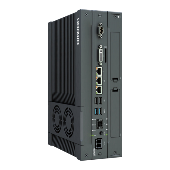
3 Hardware Overview Component Names and Functions This section shows views of the IPC Machine Controller with information about all items. 3-1-1 Front and Top of the Industrial Box PC This section shows the component names and functions for the front and top of the Box PC. Item Name Description... - Page 62 3 Hardware Overview Item Name Description Option port Interface connection options for peripheral devices or an additional monitor: • RS-232C connector • DVI-D connector • NYML connector SD Memory Card slot SD Memory Card slot PCIe bay PCI Express mounting slot DVI connector Digital Visual Interface connector 10BASE-T/100BASE-...
- Page 63 3 Hardware Overview Ports for Windows and Ports for the Controller The ports for Windows and the ports for the Machine Controller Software. Item Name Description Windows Operating Ports for the Windows Operating System. System These ports do not give access to the Machine Controller Software. Machine Controller Ethernet ports for the Machine Controller Software.
-
Page 64: Back Of The Industrial Box Pc
3 Hardware Overview 3-1-2 Back of the Industrial Box PC This section shows the component names and functions for the back of the Industrial Box PC. Item Name Description ID information label Label containing Model ID., LOT No. and other product specific information. License label Optional label containing the license number. -
Page 65: Led Indicators
3 Hardware Overview LED Indicators The Industrial Box PC has two rows of four LED indicators that show the operating status of the Box PC. Both rows have the same function. The following LED indicators are available: Item Name Description Indicator Power Indicates the operating mode of the Box PC. -
Page 66: Err Led Indicator
3 Hardware Overview 3-2-2 ERR LED Indicator The Error LED (ERR) indicates the presence and type of an error within your IPC Machine Controller. Color Status Meaning • Not lit The 24 VDC power is not supplied • No error is present •... -
Page 67: Power Button
3 Hardware Overview Power Button The power button is used to manually switch the Box PC ON and OFF. Additional Information • Refer to 6-1 Power ON on page 6 - 2 for ON details. • Refer to 6-2 Power OFF on page 6 - 4 for OFF details. 3 - 9 NY-series Industrial Box PC Hardware User's Manual (W556) -
Page 68: Drive Bays
3 Hardware Overview Drive Bays The drive bays in the IPC Machine Controller accept 2.5 inch Hard Disk Drives (HDD) or Solid State Drives (SSD). Depending on the model one or two drives are supported. Additional Information • Refer to 4-1-4 CPU Specifications on page 4 - 4 for the number of supported drives. •... -
Page 69: Sd Memory Card Slot
3 Hardware Overview SD Memory Card Slot The SD Memory Card slot on the IPC Machine Controller accepts SD Memory Cards with the following specifications. • SDHC type (SD 2.0 specification) • Up to 32 GB capacity Additional Information Refer to 3-9-2 SD Memory Cards on page 3 - 20 for SD Memory Card details. 3 - 11 NY-series Industrial Box PC Hardware User's Manual (W556) -
Page 70: Pcie Card Slot
3 Hardware Overview PCIe Card Slot The PCI Express (PCIe) Card slot of the IPC Machine Controller accepts various PCIe Cards for spe- cific hardware needs. The PCIe Card connectors are available behind the cover and the PCIe Card is mounted in the PCIe drawer Additional Information •... -
Page 71: Connectors
3 Hardware Overview Connectors This section gives an overview of the available connectors for the IPC Machine Controller. 3-7-1 Power Connector The power connector on the Box PC is used to supply 24 VDC power to the Box PC. The power connector is supplied with the Box PC. Additional Information •... -
Page 72: Usb Connectors
3 Hardware Overview Additional Information • Refer to 4-2-2 I/O Connector Specifications on page 4 - 10 for specifications. • Refer to 5-4-4 Wire the I/O Connector on page 5 - 37 for wiring details. • Refer to 5-5 Connect on page 5 - 40 for connection details. 3-7-3 USB Connectors The USB connectors support USB 2.0 and USB 3.0 specifications. -
Page 73: Ethernet Connectors
3 Hardware Overview 3-7-4 Ethernet Connectors The Ethernet connectors provide 3 individual Ethernet ports on the IPC Machine Controller. Each port offers 10BASE-T/100BASE-TX/1000BASE-T Ethernet speeds. Additional Information • Refer to 4-2-4 Ethernet Connector Specifications on page 4 - 15 for specifications. •... -
Page 74: Rs-232C Connector (Optional)
3 Hardware Overview 3-7-6 RS-232C Connector (Optional) Depending on the product configuration an optional RS-232C connector is available. Additional Information • Refer to 1-4 Product Configuration on page 1 - 6 for configuration details. • Refer to 4-2-7 RS-232C Connector Specifications on page 4 - 21 for specifications. •... -
Page 75: Ny Monitor Link Connector (Optional)
3 Hardware Overview 3-7-8 NY Monitor Link Connector (Optional) Depending on the product configuration this NY Monitor Link connector is available. The NY Monitor Link interface connector connects an OMRON Industrial PC to the OMRON Industrial Monitor. Industrial PC Industrial Monitor Additional Information •... -
Page 76: Spare Parts
3 Hardware Overview Spare Parts The following spare parts for the IPC Machine Controller are available. 3-8-1 Battery One battery is supplied with the Box PC. The battery supplies power to the real-time clock. The battery is located inside the Box PC. Model Appearance Specifications... -
Page 77: Accessory Kit
3 Hardware Overview 3-8-3 Accessory Kit The accessory kit for the Box PC. Model Appearance Specifications NY000-AK00 Accessory Kit containing all accessories sup- plied with the Box PC. • Power connector • I/O connector • Drive bracket for drive installation •... -
Page 78: Optional Hardware
Book mount NY000-AB01 Wall mount 3-9-2 SD Memory Cards SD Memory Card details are provided below. OMRON is not responsible for the operation, performance or write life of any other brand of SD Memo- ry Card. Model Appearance Card type Capacity... -
Page 79: Usb Flash Drives
3 Hardware Overview 3-9-3 USB Flash Drives USB Flash Drive details are provided below. OMRON is not responsible for the operation, performance, or write life of any other brand of USB Flash Drives. Model Appearance Capacity FZ-MEM2G 2 GB FZ-MEM8G... -
Page 80: Dvi Cables
90 mm 3-9-6 USB Type-A to USB Type-B Cables USB Type-A to USB Type-B cable details are provided below. OMRON is not responsible for the operation or performance of any other brand of USB Type-A to USB Type-B cable. Model Appearance... -
Page 81: Ny Monitor Link Cables
3 Hardware Overview 3-9-7 NY Monitor Link Cables The following table lists the recommended cables and connectors for the NY Monitor Link cable. Intra cabinet or Inter cabinet and Application light industrial en- Inter cabinet harsh industrial vironment environment Maximum length 25 m 100 m 100 m... -
Page 82: Industrial Monitor
Additional Information Refer to the OMRON website for specifications and manuals. 3-9-9 Power Supply Details for the recommended power supply are provided below. OMRON is not responsible for the operation or performance of any other power supply. Model Appearance Specifications S8VK-G£££24... -
Page 83: Ups
• Refer to 4-1-3 Power Consumption Specifications on page 4 - 3 for power consumption de- tails. • Refer to the OMRON website for S8BA specifications or to the UPS S8BA User's Manual (Cat. No. U702) for the UPS manual. - Page 84 3 Hardware Overview 3 - 26 NY-series Industrial Box PC Hardware User's Manual (W556)
-
Page 85: Specifications
Specifications This section provides specifications of the IPC Machine Controller. General Specifications ................4 - 2 4-1-1 Dimensions and Weight ................4 - 2 4-1-2 General Electrical Specifications ..............4 - 3 4-1-3 Power Consumption Specifications .............. 4 - 3 4-1-4 CPU Specifications .................. -
Page 86: General Specifications
4 Specifications General Specifications This section provides general specifications of the IPC Machine Controller. 4-1-1 Dimensions and Weight The following table provides specification details on dimensions and weights. Specifications with book Specifications with wall Item Specifications mount bracket mount brackets Dimensions Width X = 282 mm Width X = 319 mm, this is the... -
Page 87: General Electrical Specifications
4 Specifications 4-1-2 General Electrical Specifications The following table provides the general electrical specifications. Item Specifications Rated power supply voltage 24 VDC Allowable power supply voltage range 20.4 to 28.8 VDC Power supply standard SELV Grounding method Ground to less than 100 Ω Inrush current At 24 VDC: 12 A / 6 ms max. -
Page 88: Cpu Specifications
4 Specifications ® ™ The required supply specifications for a Box PC with an Intel Core i7-4700EQ CPU. Item Minimum power requirements Power supply 240 W Refer to 3-9-9 Power Supply on page 3 - 24 for power supply products. 120 W Refer to 3-9-10 UPS on page 3 - 25 for UPS products. -
Page 89: Storage Device Specifications
4 Specifications 4-1-6 Storage Device Specifications This section provides the specifications of the storage devices. Hard Disk Drive Specifications Specifications for the Hard Disk Drive (HDD) are provided in the table below. Model Specifications Item 320 GB Model NY000-AH00 S.M.A.R.T. support Rotation speed 5,400 r/min Interface... - Page 90 4 Specifications Model Specifications Item 32 GB 64 GB 128 GB Life 1500 TB/11 years at a 3000 TB/23 years at a 114 TB/3 years at a daily daily workload of 350 GB daily workload of 350 GB workload of 100 GB Refer to 1-4 Product Configuration on page 1 - 6 for product configuration details.
-
Page 91: Pcie Card Specifications
4 Specifications 4-1-7 PCIe Card Specifications The PCI Express (PCIe) Card slot of the IPC Machine Controller accepts various cards for specific hardware needs. Ensure that, according to the PCIe hardware specifications, the indent is present in the PCIe Card. The following tables provide PCIe Card details per CPU type. -
Page 92: Bracket Specifications
4 Specifications 4-1-8 Bracket Specifications The metal mounting brackets mount your Box PC and they are the connection for the functional ground. Use metal screws with a diameter of 4 mm or 5 mm to mount the brackets. Mounting screw locations for book mount and wall mount orientation: Additional Information •... -
Page 93: Connector Specifications
4 Specifications Connector Specifications This section provides the Connector Specifications of the IPC Machine Controller. 4-2-1 Power Connector Specifications The power supply connector can be locked to prevent unintentional disconnection. The connector can only be inserted the correct way. The connector is a Phoenix Contact type SPC5/2-STCL-7.62 BK (1711708). The Box PC provides protection against reverse polarity. -
Page 94: I/O Connector Specifications
4 Specifications Locking and Removing the Power Connector The power connector automatically locks into place when the black part of the connector is held and pushed in. Pushing both orange sliders towards the end of the connector will release the lock when remov- ing the connector. - Page 95 4 Specifications I/O Connector Pin Details The pin details of the I/O connector. The pin layout represents the I/O connector on the Box PC. The I/O signals connected must be powered from a power supply which conforms to the SELV stand- ards.
- Page 96 4 Specifications I/O Connector Power Status Output Details This section provides details of the Power Status Output relay. The Power Status Output is a relay between pin 1 and 2 of the I/O Connector. l Power ON Power Status Output Operation This section provides power ON details of the Power Status Output operation.
- Page 97 4 Specifications Product ON Shutdown Shutdown Product OFF start finished Closed (ON) Relay Open (OFF) Power supply removed Closed (ON) Relay Open (OFF) Additional Information Refer to 5-4-4 Wire the I/O Connector on page 5 - 37 for I/O connector wiring details. Lock and Remove the I/O Connector The I/O connector locks into place when the black part of the connector is held and pushed in.
-
Page 98: Usb Connector Specifications
4 Specifications 4-2-3 USB Connector Specifications The IPC Machine Controller includes four USB connectors. Two connectors provide version 2.0 per- formance and two connectors provide version 3.0 performance. Details of the USB interface connec- tors are provided below. The connector layout represents the USB connectors on the Box PC. Interface Connector Details •... -
Page 99: Ethernet Connector Specifications
4 Specifications 4-2-4 Ethernet Connector Specifications Details of the RJ45 Ethernet connectors are provided below. There are three Ethernet ports, each with a specific function. Following ports are available: • Ethernet (general) This port is available for the Windows Operating System. •... - Page 100 4 Specifications Ethernet Connector LED Indicators Each connector has LED indicators for speed, link and activity. Indica- Item Color Status Description Link/Act Yellow Not lit No link Link Flashing Link and activity Speed Not lit Not lit 10 Mbps or no link Green 100 Mbps link Orange...
- Page 101 4 Specifications EtherNet/IP Connector Specifications The EtherNet/IP connector is assigned to the Machine Controller Software. This port can be used for communication between the IPC Machine Controller and Ethernet/IP units. Item Specifications Ethernet connector number Physical layer 10BASE-T, 100BASE-TX or 1000BASE- Frame length 1,514 bytes max.
- Page 102 4 Specifications EtherCAT Connector Specifications The EtherCAT connector is assigned to the Machine Controller Software. This port can be used for communication between the Machine Controller Software and EtherCAT Slaves. This port acts as an EtherCAT master. Specifications for Units with Machine Controller Software. Item Specifications Ethernet connector number...
-
Page 103: Dvi Connector Specifications
4 Specifications 4-2-5 DVI Connector Specifications DVI is the standard video interface for the Box PC. The video interface depends on the model of the Box PC as specified below: Additional Information • Refer to 4-1-4 CPU Specifications on page 4 - 4 for graphics controller details. •... -
Page 104: Dvi-D Connector Specifications
4 Specifications 4-2-6 DVI-D Connector Specifications The optional video interface on the Box PC uses a DVI dual link connector. Item Specification Video interface Digital only Resolution Up to 1920 x 1200 pixels at 60 Hz Type Dual link Maximum DVI cable length Dependent upon connected monitor type and resolution Additional Information •... -
Page 105: Rs-232C Connector Specifications
4-2-8 NY Monitor Link Connector Specifications The NY Monitor Link connector connects an OMRON Industrial Monitor with an OMRON Industrial PC that has an NY monitor link connector. The NY Monitor Link communication is a combination of video and USB information. - Page 106 4 Specifications Industrial PC Industrial Monitor NY Monitor Link Connector LED Indicators The connector has LED indicators Connected and Video NYML Indica- Item Color Status Description Con- Yellow Not lit Not connected nected Connected USB communication active Video Green Not lit No video signal Blinking Video signal present...
-
Page 107: Environmental Specifications
4 Specifications Environmental Specifications This section provides environmental specifications of the IPC Machine Controller. 4-3-1 Operation Environment Specifications The following table provides the general environmental specifications for the Industrial Box PC. Item Specifications Ambient operating temperature 0 to 55°C Ambient storage temperature -20 to 70°C Ambient operating humidity 10% to 90% with no condensation... -
Page 108: Temperature And Humidity Specifications
4 Specifications 4-3-2 Temperature and Humidity Specifications The allowed ambient operating temperature and ambient humidity depend on product type, CPU type, mounting orientation, and storage device type. The following sections provide temperature and humidity details per CPU type. Temperature and Humidity Graphs The maximum ambient operating temperature and ambient humidity are specified per CPU type, mounting orientation and storage device type. - Page 109 4 Specifications • Store the Box PC with a SSD within the general environmental specifications. • Store the Box PC with a HDD within the ambient temperature and humidity ranges as shown in fol- lowing graph. Storage temperature- Storage humidity range temperature-humidity range Temperature [°C]...
-
Page 110: Recycling Specifications
4 Specifications 4-3-3 Recycling Specifications The following table provides recycling information for the IPC Machine Controller. Part Recycle specifications Battery Chemical waste PCIe Card and other electrical components Electrical waste Precautions for Safe Use Dispose of the product and batteries according to local ordinances as they apply. 4 - 26 NY-series Industrial Box PC Hardware User's Manual (W556) -
Page 111: Installation
Installation This section provides all installation details for the IPC Machine Controller. Unpack ......................5 - 2 5-1-1 Unpack Procedure ..................5 - 2 5-1-2 Items Supplied ....................5 - 3 Install Options ....................5 - 5 5-2-1 Install a Drive ....................5 - 5 5-2-2 Install the PCIe Card.................. -
Page 112: Unpack
5 Installation Unpack This section provides details on how to unpack the IPC Machine Controller. 5-1-1 Unpack Procedure Check the package for damage. If there is any visible damage: • Take photos of the package and save them. • Inform your supplier immediately. Open the package. -
Page 113: Items Supplied
5 Installation 5-1-2 Items Supplied The Industrial Box PC is supplied with several items. Additional Information • Refer to Items Supplied with the Industrial Box PC on page 5 - 3 for more details. • Refer to Items Supplied with the Brackets on page 5 - 4 for more details. Items Supplied with the Industrial Box PC This section describes the items supplied with your Industrial Box PC. - Page 114 5 Installation Items Supplied with the Brackets This section describes the items supplied with the brackets for your Industrial Box PC. Additional Information • Refer to 3-9-1 Mounting Brackets on page 3 - 20 for bracket details. • Refer to 5-3-8 Book Mount Procedure on page 5 - 24 for book mount installation. •...
-
Page 115: Install Options
5 Installation Install Options This section describes the installable options for the IPC Machine Controller. 5-2-1 Install a Drive A drive is a storage device for the IPC Machine Controller. Additional Information • Depending on the product configuration a drive is already installed. Refer to 1-4 Product Configuration on page 1 - 6 for storage details. - Page 116 5 Installation Pull the metal shielding cover out of the Box PC. Align the connectors of the drive as shown on the bracket. Then insert the replacement drive in the bracket and insert the 4 mounting screws . Tighten these screws with a tor- que of 0.35 N·m.
- Page 117 5 Installation Insert the bracket with the drive in the correct bay. • A drive for the operating system has to be inserted in bay A • The drive for additional storage can be inserted in bay B Ensure the bracket is completely in the Box PC with an extra push. The drive bracket will lock into place when it is fully inserted.
- Page 118 5 Installation Mount the drive cover. The lock lever will click when closed correctly. Finalize the drive installation when the Box PC installation is completed. • If the drive is inserted in bay A: (1) Install an operating system (2) Power OFF and then Power ON (3) Ensure the drive is functional and confirm normal operation.
-
Page 119: Install The Pcie Card
5 Installation 5-2-2 Install the PCIe Card Prepare the following items: • The PCIe Card. A PCIe Card is not supplied with the Box PC. Additional Information Refer to 4-1-7 PCIe Card Specifications on page 4 - 7 for PCIe specifications. •... - Page 120 5 Installation Pull the middle of the Card Clip to unlock it and remove it from the PCIe Drawer. Remove the slot cover from the PCIe Drawer. The thin sheet metal frame should stay in the PCIe Drawer. The slot cover is now removed. 5 - 10 NY-series Industrial Box PC Hardware User's Manual (W556)
- Page 121 5 Installation Place the PCIe Card in the PCIe Drawer. Ensure to insert the PCIe Card in the correct opening. Ensure the thin sheet metal frame is positioned between the PCIe Card and the PCIe Drawer to ensure a good conductive contact. Place the Card Clip in the PCIe Card and PCIe Drawer and then rotate the Clip to lock it...
- Page 122 5 Installation Slide the Card Support so that it supports the side of the PCIe Card. The card should be in small groove so there is support below and above the card. Rotate the Card Support to lock it in place. Insert the PCIe Drawer in the Box PC and then insert the two crosshead screws that hold the PCIe Drawer in place.
- Page 123 5 Installation Remove the PCIe cover if the PCIe Card has external connectors. (1) Push the lock lever (2) Tilt the PCIe cover (3) Remove the PCIe cover The PCIe Card is installed. 5 - 13 NY-series Industrial Box PC Hardware User's Manual (W556)
-
Page 124: Mount
5 Installation Mount This section describes how to mount the Box PC in either a book or wall orientation inside a control panel. WARNING Ensure that installation and post-installation checks of the product are performed by personnel in charge who possess a thorough understand- ing of the machinery to be installed. -
Page 125: Product Orientation
5 Installation 5-3-2 Product Orientation The Box PC can be mounted in a book or wall orientation. • For book mount there is one allowed orientation • For wall mount there are two allowed orientations, horizontally mounted and vertically mounted Do not install the Box PC in other orientations. - Page 126 5 Installation Provide enough space for good air flow and ensure the following minimum distances are observed around the sides of the Box PC. • Book Mount • Wall Mount in landscape or portrait orientation Item Minimum distance 50 mm 100 mm 50 mm Measure the minimum distances X and Y at the air openings in the sides of the Box PC.
- Page 127 Box PC. • Do not install the Box PC directly above any heat-generating equipment, such as heaters or transformers. • Do not install the Box PC in a location exposed to direct sunlight. OMRON product OMRON product...
-
Page 128: Humidity
5 Installation OMRON product OMRON product Forced Air Circulation l Room Cooling Cool the entire room where the control panel is located. Cooler Control panel Room Cooling Low Temperatures The Box PC may not start normally if the temperature is below 0°C when the power is turned ON. -
Page 129: Atmosphere
Installation Location Install the Box PC as far away as possible from high-voltage (600 V or higher) and power devices to ensure safe operation and maintenance. Example of Recommended Equipment Arrangement OMRON product Control panel Control panel High-voltage... - Page 130 • Keep the wiring between the transformer and the Box PC as short as possible, twist the wires well, and keep the wiring separate from high-voltage and power lines. Power circuits Power supply for general operations circuits I/O power supply for Omron product I/O power supply for Omron product Noise Unit power supply for Omron product...
- Page 131 5 Installation Wire External I/O Signal Lines Observe the following points when wiring the external I/O signal lines. • To absorb reverse electromotive force when an inductive load is connected to an output signal, con- nect a surge suppressor near the inductive load in an AC circuit, or connect a diode near the induc- tive load in a DC circuit.
- Page 132 5 Installation • Power lines and signal lines • Input signals and output signals • Analog signals and digital signals • High-level signals and low-level signals • Communications lines and power lines • DC signals and AC signals • High-frequency devices (such as Inverters) and signal lines (communications) l (Routing of) Wiring Observe the following points when wiring power supply and signal cables.
- Page 133 Ground of 200 mm 100 Ω or less Example: Separating an OMRON product from Power Lines l Wiring Ducts Whenever possible, route the cables and wires through wiring ducts. Install the wiring ducts so that it is easy to route the wires from the IPC Machine Controller directly into the duct.
-
Page 134: Book Mount Procedure
5 Installation 5-3-8 Book Mount Procedure Use the following procedure to mount the IPC Machine Controller in the book orientation. Additional Information • Refer to 5-4-2 Ground on page 5 - 27 for grounding details. • Refer to 3-9-1 Mounting Brackets on page 3 - 20 for the bracket model. To mount the Box PC: Mount the Bracket to the Industrial Box PC... -
Page 135: Wall Mount Procedure
5 Installation • Insert screws through the bracket into the mounting surface. Note that these screws are not in the scope of delivery. • Tighten all four screws with a torque of 0.5 N·m. The Box PC is mounted. 5-3-9 Wall Mount Procedure Use the following procedure to mount the Box PC in the wall orientation. -
Page 136: Wire
5 Installation Wire This section describes how to wire the IPC Machine Controller. 5-4-1 Wiring Warnings and Cautions This section describes the Warnings and Cautions when wiring the IPC Machine Controller. WARNING If external power supplies for slaves or other devices are overloaded or short-circuited, the voltage will drop, outputs will turn OFF, and the sys- tem may be unable to read inputs. -
Page 137: Ground
5 Installation 5-4-2 Ground This section describes how to ground the IPC Machine Controller. WARNING Always connect to a ground of 100 Ω or less when installing the prod- uct. Caution The product has an internal non-isolated DC power supply. Circuit ground (0 VDC) and frame ground are connected together. - Page 138 5 Installation Considerations for Earthing Methods Local potential fluctuations due to lightning or noise occurred by power devices will cause potential fluctuations between ground terminals of devices. This potential fluctuation may result in device mal- function or damage. To prevent this, it is necessary to suppress the occurrence of a difference in elec- trical potential between ground terminals of devices.
- Page 139 5 Installation Equipotential Bonding System Equipotential bonding is an earthing method in which steel frames and building structures, metal ducts and pipes, and metal structures in floors are connected together and make connections to the earth trunk line to achieve a uniform potential everywhere across the entire building. We recommend this earthing method.
- Page 140 5 Installation Star Earthing If the earthing method used for the building is not equipotential bonding or the earthing system is un- known, choose (a) from among the earthing methods given below. (a) Connecting devices and noise sources to separate earth electrodes This is an earthing method to separately ground an earth electrode of the device that is connected with a communications cable or other devices and an earth electrode of a high-power device that could be a noise source, such as a motor or inverter.
- Page 141 5 Installation Daisy Chain This is an earthing method to connect the device that is connected with a communications cable, other devices, and a device that could be a noise source using a daisy-chain topology to a common earth electrode. This earthing method is not recommended because the device that could be a noise source may inter- fere electromagnetically with other devices.
- Page 142 5 Installation Ground Connection Details This section provides details about the ground connection. Use the functional ground terminal on the mounting bracket(s) to ground your Industrial Box PC. The washers and nut are supplied with the bracket(s). Refer to Items Supplied with the Brackets on page 5 - 4 for details. Book Mount Mount the ground connection wire to the functional ground terminal...
- Page 143 5 Installation l Crimp terminals Use crimp terminals with dimensions X = M4 and Y = 8 mm max. 5 - 33 NY-series Industrial Box PC Hardware User's Manual (W556)
-
Page 144: Wire The Power Connector
5 Installation 5-4-3 Wire the Power Connector This section describes how to wire the power connector. Precautions for Safe Use • Do not perform a dielectric strength test. • Always use the recommended uninterruptible power supply (UPS) to prevent data loss and other system file integrity issues caused by unexpected power interruption. - Page 145 Maximum AWG according to UL/cUL • Power Supply Connector DC Power Supply The OMRON S8VK-series power supply is recommended for use with the IPC Machine Controller. Additional Information • Refer to 3-9-9 Power Supply on page 3 - 24 for more information.
- Page 146 5 Installation Power Connector Wiring Procedure Use the following procedure to wire the power connector. 7 mm Remove the sheath from the power supply wires. Precautions for Safe Use Observe the following precautions to prevent broken wires. • When you remove the sheath, be careful not to damage the conductor. •...
-
Page 147: Wire The I/O Connector
5 Installation 5-4-4 Wire the I/O Connector This section describes how to wire the I/O connector. I/O Connector Wiring Materials Use the supplied I/O connector to connect the inputs and outputs to the IPC Machine Controller. Recommended I/O conductor sizes for the connector are provided in the table. Wire type Conductor cross-section Solid conductor... - Page 148 5 Installation Description Internal Circuit Details Power ON Input The Power ON Input and the UPS Mode Input are bi-di- rectional and isolated. Each input can be wired as sinking (NPN) or sourcing (PNP). Wire these according to the UPS Mode Input output device connected to the inputs.
- Page 149 5 Installation I/O Connector Wiring Procedure Use the following procedure to wire the I/O connector. 7 mm Remove the sheath from the wires. Precautions for Safe Use Observe the following precautions to prevent broken wires. • When you remove the sheath, be careful not to damage the conductor. •...
-
Page 150: Connect
5 Installation Connect This section describes how to connect the IPC Machine Controller. 5 - 40 NY-series Industrial Box PC Hardware User's Manual (W556) -
Page 151: Connector Identification
5 Installation 5-5-1 Connector Identification The Industrial Box PC connectors are shown below. Item Name Description Power connector Lockable power connector I/O connector 2 inputs (UPS signal and power OFF control) and 1 output (Industri- al Box PC power state) USB 3.0 connector 2 USB 3.0 connectors USB 2.0 connector... -
Page 152: Connection Procedure
5 Installation 5-5-2 Connection Procedure Use the following procedure to connect the IPC Machine Controller. Ensure the Box PC is securely fastened to the mounting surface. Ensure the mounted Box PC can be connected to power and peripheral devices. Remove dust covers where applicable and store them in a safe place. - Page 153 5 Installation Connect the I/O connector. Hold the black part when inserting the connector, this enables the auto-locking mechanism. Do not tilt the orange levers because this will unlock the connector. Connect an external monitor such as the Industrial Monitor. Connect the monitor to the DVI interface and tighten the fastening screws or use the optional NYML connector.
-
Page 154: Ethernet Connection Procedure
5 Installation 5-5-3 Ethernet Connection Procedure Use the following procedure to connect the Ethernet connectors of the IPC Machine Controller. Remove the dust caps from the Ethernet ports to be connected. Connect Ethernet Port 1 of the Box PC to a normal Ethernet network. Connect Ethernet port 2 of the Box PC to the Ethernet/IP network. -
Page 155: Connect Ups
• Always use an uninterruptable power supply (UPS) to prevent data loss and other system file integrity issues caused by unexpected power interruption. • Use an Omron S8BA UPS with the correct revision number to prevent improper system shut- down. - Page 156 5 Installation Follow the steps below to connect the S8BA UPS to the I/O connector of the Box PC and to configure it correctly. Refer to 5-4-4 Wire the I/O Connector on page 5 - 37 for I/O Connector details. Ensure the revision number of the UPS is correct.
- Page 157 5 Installation • Create a power interruption • Monitor the shutdown sequence and confirm a correct shutdown sequence The UPS is connected and configured. The Box PC will shut down properly in case of a power supply interruption and restart automatically when the power is restored.
-
Page 158: Initial Power On
Ensure that the connected monitor(s) is powered ON. Connect a keyboard and/or mouse. • If using an OMRON Industrial Monitor, this may not be required because it has touch func- tionality. • Do not connect additional storage devices before the installation of the operating system completed. -
Page 159: Operating Procedures
Operating Procedures This section provides the operating procedures for the IPC Machine Controller. Power ON ...................... 6 - 2 6-1-1 Power ON Using the Power Button .............. 6 - 2 6-1-2 Power ON Using the Power ON/OFF Input ..........6 - 2 6-1-3 Power ON Using Safe Mode................. -
Page 160: Power On
6 Operating Procedures Power ON This section provides Power ON details. 6-1-1 Power ON Using the Power Button Start condition: Power is supplied to the Box PC and the Box PC is OFF. Press the power button and release within 1 second. Refer to 3-3 Power Button on page 3 - 9 for the power button location. -
Page 161: Power On Using Safe Mode
6 Operating Procedures 6-1-3 Power ON Using Safe Mode Start condition: The IPC Machine Controller is OFF. Additional Information Use this procedure to start the Box PC without starting the Machine Controller Software. Remove the power supply connector. Press and hold the power button on the Box PC. Connect the power supply connector while pressing the power button. -
Page 162: Power Off
6 Operating Procedures Power OFF This section provides Power OFF details. Before following power OFF procedures below, check that the IPC Machine Controller is ON by exam- ining the LED indicators on the Box PC. 6-2-1 Power OFF Using the Power Button Ensure all programs are closed. -
Page 163: Forced Power Off Using The Power Button
6 Operating Procedures 6-2-3 Forced Power OFF Using the Power Button Precautions for Safe Use Press the power button for several seconds to force the product shutdown. Always back up files in the planned way to prevent data loss or system file corruption. Ensure all programs are closed. - Page 164 6 Operating Procedures 6 - 6 NY-series Industrial Box PC Hardware User's Manual (W556)
-
Page 165: Maintenance
Maintenance This section provides an overview of all maintenance tasks for the IPC Machine Con- troller. Preventive Maintenance ................7 - 2 7-1-1 Preventive Maintenance Schedule ............... 7 - 2 7-1-2 Clean the Box PC ..................7 - 3 Corrective Maintenance................7 - 4 7-2-1 Remove the Cover.................. -
Page 166: Preventive Maintenance
Refer to 3-2 LED Indicators on page 3 - 7 for LED details. Monitor storage devices that do not Refer to Storage Device Considerations on page 3 - 21 for details. comply to the Omron specifications Weekly Reference Clean the Box PC Refer to 7-1-2 Clean the Box PC on page 7 - 3 for cleaning details. -
Page 167: Clean The Box Pc
7 Maintenance 7-1-2 Clean the Box PC Clean the Box PC periodically in order to keep it in the best operating condition. Wipe the Box PC with a dry, soft cloth. Precautions for Safe Use Do not use corrosive substances to clean the product. Doing so may result in the failure or malfunction. -
Page 168: Corrective Maintenance
7 Maintenance Corrective Maintenance Corrective maintenance covers all actions to correct problems that cause downtime. WARNING Do not attempt to disassemble, repair, or modify the product in any way. Doing so may result in malfunction or fire. Additional Information Refer to the NY-series Troubleshooting Manual (Cat. No. W564) for troubleshooting details. 7-2-1 Remove the Cover The Cover of the IPC Machine Controller provides access to the following items. -
Page 169: Replace The Fan Unit
7 Maintenance (2) Lift the side to tilt the Cover. (3) Remove the complete Cover. The Cover is removed. To mount the Cover, position the side of the Cover in the Box PC and push the cover in place. The lever will lock in place. 7-2-2 Replace the Fan Unit The fans are mounted in the Fan Unit. - Page 170 7 Maintenance Replace the complete Fan Unit. (1) Push the lever to unlock the Fan Unit. (2) Lift the lever to tilt the Fan Unit. (3) Remove the complete Fan Unit. Insert the new Fan Unit in the Box PC. Ensure the end of the Fan Unit is positioned under the fan guide Connect the Fan Connectors to the board.
-
Page 171: Replace The Battery
7 Maintenance 7-2-3 Replace the Battery Precautions for Safe Use • The Battery may leak, rupture, heat, or ignite. Never short-circuit, charge, disassemble, heat, or incinerate the Battery or subject it to strong shock. • Dispose of any Battery that has been dropped on the floor or otherwise subjected to exces- sive shock. - Page 172 7 Maintenance Lift the battery from the compartment. Disconnect the battery from the battery connector Connect the new battery to the battery connector. Place the new battery in the Box PC. Ensure the wires are at the side of the battery and not on top of the battery. If the wires are on top of the battery this might make closing and opening the cover more difficult.
-
Page 173: Replace A Drive
7 Maintenance 7-2-4 Replace a Drive Use the following procedure to replace a drive. Prepare the new drive. Additional Information • Refer to 1-4 Product Configuration on page 1 - 6 for the installed drive model. • Refer to 3-9-4 Storage Devices on page 3 - 21 for the available drive models. •... - Page 174 7 Maintenance Pull the metal shielding cover out of the Box PC. Insert the drive cover in the drive bracket bay and move it down so that it locks in the drive bracket. 7 - 10 NY-series Industrial Box PC Hardware User's Manual (W556)
- Page 175 7 Maintenance Remove the drive bracket from the Box PC using the drive cover. Remove the 4 mounting screws and then remove the drive from the drive bracket. 7 - 11 NY-series Industrial Box PC Hardware User's Manual (W556)
- Page 176 7 Maintenance Align the connectors of the replacement drive as shown on the bracket. Then insert the re- placement drive in the bracket and insert the 4 mounting screws . Tighten these screws with a torque of 0.35 N·m. Insert the bracket with the replacement drive into the correct bay of the Box PC. Ensure the bracket is completely in the Box PC with an extra push.
- Page 177 7 Maintenance Insert the metal shielding cover. Mount the drive cover. The lock lever will click when closed correctly. Restore the drive data. • For products NYB£ and NYP£: • For an Industrial PC with RTOS Controller restore the drive data from a backup. •...
-
Page 178: Replace The Pcie Card
7 Maintenance 7-2-5 Replace the PCIe Card Use the following procedure to replace the PCIe Card. Prepare: • The PCIe Card Additional Information Refer to 4-1-7 PCIe Card Specifications on page 4 - 7 for PCIe specifications. • The PCIe Card mounting materials: Card Clip and Card Support These are supplied with the IPC Machine Controller. - Page 179 7 Maintenance Push the notch at the bottom of the Card Support up and rotate the Card Support. Slide the Card Support away from the card to create space and to remove it. Pull the middle of the Card Clip to unlock it and remove it from the PCIe Drawer. 7 - 15 NY-series Industrial Box PC Hardware User's Manual (W556)
- Page 180 7 Maintenance Remove the PCIe Card from the PCIe Drawer. The PCIe Card is now removed. Place the replacement PCIe Card in the PCIe Drawer. Ensure the PCIe Card is inserted into the correct opening. 7 - 16 NY-series Industrial Box PC Hardware User's Manual (W556)
- Page 181 7 Maintenance Place the Card Clip in the PCIe Card and PCIe Drawer and then rotate the Clip to lock it in place. Slide the Card Support so that it supports the side of the PCIe Card. Rotate the Card Support to lock it in place.
- Page 182 7 Maintenance Insert the PCIe Drawer in the Box PC and then insert the two crosshead screws that hold the PCIe Drawer in place. Remount the Box PC. Confirm normal operation. The PCIe Card is replaced. 7 - 18 NY-series Industrial Box PC Hardware User's Manual (W556)
- Page 183 Appendices BIOS ......................A - 2 A-1-1 BIOS Overview ..................... A - 2 A-1-2 BIOS - Main ....................A - 4 A-1-3 BIOS - Advanced ..................A - 5 A-1-4 BIOS - Chipset....................A - 8 A-1-5 BIOS - Boot....................A - 9 A-1-6 BIOS - Security ...................
-
Page 184: A-1 Bios
Appendices A-1 BIOS This section provides the BIOS information of the IPC Machine Controller. WARNING Changing BIOS information is only allowed for the engineer in charge that possesses a thorough understanding of the BIOS settings because it can change the behavior of the product. A-1-1 BIOS Overview The BIOS contains settings that influence the behavior of the IPC Machine Controller. - Page 185 Appendices Refer to A-1-5 BIOS - Boot on page A - 9 for Boot details. • Security Refer to A-1-6 BIOS - Security on page A - 10 for Security details. • Save & Exit Refer to A-1-7 BIOS - Save & Exit on page A - 10 for Save and Exit details. BIOS - Navigation and Function Keys The right part of the BIOS screens is divided in two parts.
-
Page 186: A-1-2 Bios - Main
Appendices BIOS Password & Write Protection A BIOS password protects the BIOS setup program from unauthorized access. This ensures that users cannot change the system configuration without authorization. With an assigned BIOS pass- word, the BIOS prompts the user for a password on a setup entry. If the password entered is wrong, the BIOS setup program will not launch. -
Page 187: A-1-3 Bios - Advanced
Appendices A-1-3 BIOS - Advanced This section provides advanced BIOS information. Changeable BIOS Advanced parameters and their factory default values: Item Default / Remark Machine Control Enabled Graphics Primary Graphics Device Auto Internal Graphics Device Auto IGD Pre-Allocated Graphics Memory IGD Total Graphics Memory 256M Primary IGD Boot Display Device... - Page 188 Appendices Item Default / Remark PCI & PCI Express PCI Express Gen 2 Set- Completion Timeout Default tings ARI Forwarding Disabled AtomicOp Requester En- Disabled able AtomicOp Egress Block- Disabled IDO Request Enable Disabled IDO Completion Enable Disabled LTR Mechanism Enable Disabled End-End TLP Prefix Disabled...
- Page 189 Appendices Item Default / Remark PCI & PCI Express GbE Channel 0 PCI Express Port 0 Enabled ASPM Disabled GbE Channel 1 PCI Express Port 1 Enabled ASPM Disabled PCI Express Port 0, 1 (x4 PEG1 Speed Auto Gen3) PEG1 ASPM Disabled PEG1 De-emphasis Con- -3.5 dB...
-
Page 190: A-1-4 Bios - Chipset
Appendices Item Default / Remark UEFI Network Stack UEFI Network Stack Disabled NVMe Configuration NVMe Configuration information Display of NVMe Configu- ration parameters Intel® Ethernet NIC Configuration Link Speed Auto Negotiated Connection I218-LM - Wake On LAN Enabled Unique MAC Address Blink LEDs Smart Self Test monitors the status of the HDD/SSD. -
Page 191: A-1-5 Bios - Boot
Appendices A-1-5 BIOS - Boot Provides Boot information and configuration settings. Changeable BIOS Boot parameters and their factory default values: Item Default / Remark Quiet Boot Disabled Setup Prompt Timeout Bootup NumLock State Battery Support Auto (Battery Manager) Remain Off Power Loss Control CSM &... -
Page 192: A-1-6 Bios - Security
Appendices A-1-6 BIOS - Security Provides security information like BIOS Password and HDD information. WARNING Security setting adjustments should only be performed by the engineer in charge that possesses a thorough understanding of the security set- tings. Selecting non-recommended security settings can put your sys- tem at risk. -
Page 193: A-2 Allocate A Drive In Windows
Appendices A-2 Allocate a Drive in Windows An added drive must be allocated before it becomes visible in Windows. To allocate a drive in Windows: Ensure the Box PC is ON. Select the Windows Start Button. In the search field, input partition. Select Create and format hard disk partitions. -
Page 194: A-3 Dvi Connector Pin Details
Appendices A-3 DVI Connector Pin Details This section provides the pin details for the DVI-I and the DVI-D connectors. A-3-1 DVI-I Connector Pin Details Pin details of the DVI-I connector. C1 C2 C3 C4 The pin layout represents the DVI-I connector on the IPC Machine Controller. Pin numbers increase from left to right for every row. -
Page 195: A-3-2 Dvi-D Connector Pin Details
Appendices Signal Name Function TMDS clock+ Digital clock+ TMDS clock− Digital clock− Analog red ® ™ For Intel Core i7-4700EQ CPU type Analog green ® ™ For Intel Core i7-4700EQ CPU type Analog blue ® ™ For Intel Core i7-4700EQ CPU type Analog horizontal sync ®... - Page 196 Appendices Signal Name Function TMDS data 0− Digital blue− (link 1) and digital sync TMDS data 0+ Digital blue+ (link 1) and digital sync 0 VDC TMDS data 0/5 shield Not connected Not connected 0 VDC TMDS clock shield TMDS clock+ Digital clock+ TMDS clock−...
-
Page 197: A-4 Rs-232C Connector Pin Details
Appendices A-4 RS-232C Connector Pin Details The pin layout represents the RS-232C connector on the Box PC. Signal Name 0 VDC The 0 VDC pin is internally connected to the ground connection. Additional Information Refer to 5-4-2 Ground on page 5 - 27 for grounding details. A - 15 NY-series Industrial Box PC Hardware User's Manual (W556) - Page 198 Appendices A - 16 NY-series Industrial Box PC Hardware User's Manual (W556)
- Page 199 Index I - 1 NY-series Industrial Box PC Hardware User's Manual (W556)
- Page 200 Index Index Link/Act Indicator ............4 - 16 Specifications ............4 - 15 Speed Indicator ............4 - 16 Accessory kit ..............3 - 19 Battery ..............3 - 18,7 - 4 Fan error .................3 - 8 Replace ...............7 - 7 Fan Unit ................ 3 - 18 Replacement ...............7 - 4 Replace ...............7 - 5 Battery low ..............3 - 8...
- Page 201 Index Specifications ..............4 - 7 Weights ................4 - 2 Power button ..............3 - 9 Wire ................5 - 26 Power connector ............3 - 13 Wiring Specifications ..............4 - 9 Warnings ..............5 - 26 Wiring ..............5 - 34,5 - 36 Power consumption ............
- Page 204 The Netherlands Hoffman Estates, IL 60169 U.S.A. Tel: (31)2356-81-300/Fax: (31)2356-81-388 Tel: (1) 847-843-7900/Fax: (1) 847-843-7787 © OMRON Corporation 2016-2017 All Rights Reserved. OMRON (CHINA) CO., LTD. OMRON ASIA PACIFIC PTE. LTD. In the interest of product improvement, Room 2211, Bank of China Tower, No.
Need help?
Do you have a question about the NY532-1*00-112*13**0 and is the answer not in the manual?
Questions and answers