Sign In
Upload
Manuals
Brands
Omron Manuals
Industrial PC
NY532-1*00-112*13**0
User Manuals: Omron NY532-1*00-112*13**0 Box PC
Manuals and User Guides for Omron NY532-1*00-112*13**0 Box PC. We have
2
Omron NY532-1*00-112*13**0 Box PC manuals available for free PDF download: User Manual
Omron NY532-1*00-112*13**0 User Manual (214 pages)
Industrial Panel PC
Brand:
Omron
| Category:
Touch Panel
| Size: 9 MB
Table of Contents
Intended Audience
3
Applicable Products
3
Introduction
3
Relevant Manuals
4
Table of Contents
6
Manual Information
11
Page Structure
11
Special Information
12
Terms and Conditions Agreement
13
Warranty and Limitations of Liability
13
Application Considerations
14
Disclaimers
14
Safety Precautions
16
Definition of Precautionary Information
16
Symbols
16
Warnings
17
Cautions
19
Precautions for Safe Use
20
Disassembly, Dropping, Mounting, Installation and Storage
20
Wiring
20
Power Supply Design and Turning ON/OFF the Power Supply
21
Actual Operation
21
Operation
22
General Communications
23
Ethernet/Ip Communications
23
Ethercat Communications
23
Motion Control
24
Restoring Data
25
Battery Replacement
25
Product Replacement
25
Cleaning, Maintenance and Disposal
25
Precautions for Correct Use
27
Storage, Installation and Mounting
27
Wiring
27
Actual Operation and Operation
28
Error Processing
28
Restoring Data
29
Task Settings
29
Motion Control
29
Ethercat Communications
29
Battery Replacement
29
SD Memory Cards
30
Cleaning and Maintenance
30
Regulations and Standards
31
Conformance to EU Directives
31
Conformance to KC Standards
32
Conformance to UL and CSA Standards
32
Software Licenses and Copyrights
32
Versions
33
Check Unit Versions
33
Check Hardware Revision
33
Related Manuals
35
Related IPC Machine Controller Manuals
35
Related Products Manuals
37
Terminology and Abbreviations
38
Industrial PC Platform
38
Hardware
38
Software
39
Revision History
40
Sections in this Manual
41
Intended Use
44
Features
45
Hardware Features
45
Machine Controller Software Features
46
ID Information Label
47
Product Configuration
48
Overall Operating Procedure
49
System Configurations
51
Basic Configurations
52
Ethercat Network Configuration
53
Related Ethercat Hardware
54
Ethernet/Ip Network Configuration
55
Related Ethernet/Ip Hardware
55
Connection with the Sysmac Studio
57
Configurations that Allow Online Connections
57
Configurations that Do Not Allow Online Connections
58
Hardware Overview
59
Component Names and Functions
60
Front and Top of the Industrial Panel PC
60
Back and Bottom of the Industrial Panel PC
61
LED Indicators
64
Bottom LED Indicators
64
Front LED and LED Indicator
66
Power Button
69
Drive Bays
70
SD Memory Card Slot
71
Pcie Card Slot
72
Connectors
73
Power Connector
73
I/O Connector
73
USB Connectors
74
Ethernet Connectors
75
DVI Connector
75
RS-232C Connector (Optional)
76
DVI-D Connector (Optional)
76
NY Monitor Link Connector (Optional)
77
Spare Parts
78
Battery
78
Fan Unit
78
Accessory Kit
79
Optional Hardware
80
SD Memory Cards
80
USB Flash Drives
80
Storage Devices
81
DVI Cables
82
USB Type-A to USB Type-B Cables
82
NY Monitor Link Cables
83
Industrial Monitor
84
Power Supply
84
Ups
85
UPS Communication Cable
85
Specifications
87
General Specifications
88
Dimensions and Weight
88
General Electrical Specifications
89
Power Consumption Specifications
90
CPU Specifications
91
Memory Specifications
91
Storage Device Specifications
92
Pcie Card Specifications
93
Connector Specifications
94
Power Connector Specifications
94
I/O Connector Specifications
95
USB Connector Specifications
99
Ethernet Connector Specifications
101
DVI Connector Specifications
104
DVI-D Connector Specifications
105
RS-232C Connector Specifications
106
NY Monitor Link Connector Specifications
106
Display Specifications
108
Environmental Specifications
109
Operation Environment Specifications
109
Temperature and Humidity Specifications
110
Recycling Specifications
112
Installation
113
Unpack
114
Unpack Procedure
114
Items Supplied
115
Install Options
116
Install a Drive
116
Install the Pcie Card
120
Mount
125
Installation Method in Control Panels
125
Product Orientation
126
Temperature
127
Humidity
129
Vibration and Shock
129
Atmosphere
130
Electrical Environment
130
Prepare the Mounting Surface
135
Mount the Panel PC
137
Wire
138
Wiring Warnings and Cautions
138
Ground
139
Wire the Power Connector
145
Wire the I/O Connector
148
Connect
151
Connector Identification
152
Connection Procedure
153
Ethernet Connection Procedure
155
Connect UPS
156
Initial Power on
159
Initial Power on Procedure
159
Operating Procedures
161
Touchscreen Operation
162
Power on
163
Power on Using the Power Button
163
Power on Using the Power ON/OFF Input
163
Power on Using Safe Mode
164
Auto Power on
164
Power off
165
Power off Using the Power Button
165
Power off Using the Power ON/OFF Input
165
Forced Power off Using the Power Button
166
Maintenance
167
Preventive Maintenance
168
Preventive Maintenance Schedule
168
Clean the Touchscreen Surface
170
Clean the Panel PC
170
Check the Gasket Seal
171
Corrective Maintenance
172
Remove the Cover
173
Replace the Fan Unit
174
Replace the Battery
176
Replace a Drive
178
Replace the Pcie Card
183
Correct Display Functionality When Nothing Is Displayed
188
Correct Touchscreen Functionality
189
A-1 Bios
194
A-1-1 BIOS Overview
194
BIOS Overview
194
A-1-2 BIOS - Main
196
A-1-3 BIOS - Advanced
197
A-1-4 BIOS - Chipset
200
A-1-5 BIOS - Boot
201
A-1-6 BIOS - Security
202
A-1-7 BIOS - Save & Exit
202
BIOS - Security
202
BIOS - Save & Exit
202
A-2 Allocate a Drive in Windows
203
A-3 DVI Connector Pin Details
204
A-3-1 DVI-I Connector Pin Details
204
DVI-I Connector Pin Details
204
A-3-2 DVI-D Connector Pin Details
205
A-4 RS-232C Connector Pin Details
207
Advertisement
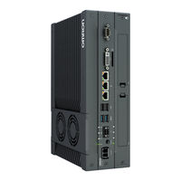
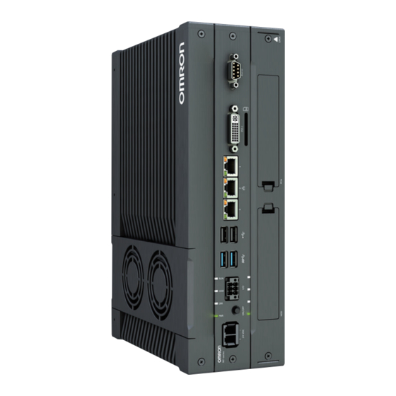
Omron NY532-1*00-112*13**0 User Manual (204 pages)
Industrial Box PC NY-series
Brand:
Omron
| Category:
Industrial PC
| Size: 9 MB
Table of Contents
Intended Audience
3
Applicable Products
3
Introduction
3
Relevant Manuals
4
Table of Contents
6
Manual Information
11
Page Structure
11
Special Information
12
Terms and Conditions Agreement
13
Warranty and Limitations of Liability
13
Application Considerations
14
Disclaimers
14
Safety Precautions
16
Definition of Precautionary Information
16
Symbols
16
Warnings
17
Cautions
19
Precautions for Safe Use
20
Disassembly, Dropping, Mounting, Installation and Storage
20
Wiring
20
Power Supply Design and Turning ON/OFF the Power Supply
20
Actual Operation
21
Operation
21
General Communications
22
Ethernet/Ip Communications
22
Ethercat Communications
22
Motion Control
23
Restoring Data
24
Battery Replacement
24
Product Replacement
25
Cleaning, Maintenance and Disposal
25
Precautions for Correct Use
26
Storage, Installation and Mounting
26
Wiring
26
Actual Operation and Operation
27
Error Processing
27
Restoring Data
28
Task Settings
28
Motion Control
28
Ethercat Communications
28
Battery Replacement
28
SD Memory Cards
29
Regulations and Standards
30
Conformance to EU Directives
30
Conformance to KC Standards
31
Conformance to UL and CSA Standards
31
Software Licenses and Copyrights
31
Versions
32
Check Unit Versions
32
Check Hardware Revision
32
Related Manuals
34
Related IPC Machine Controller Manuals
34
Related Products Manuals
36
Terminology and Abbreviations
37
Industrial PC Platform
37
Hardware
37
Software
38
Revision History
39
Sections in this Manual
41
Intended Use
44
Features
45
Hardware Features
45
Machine Controller Software Features
46
ID Information Label
47
Label with Controller License (Optional)
47
Product Configuration
48
Overall Operating Procedure
49
System Configurations
51
Basic Configurations
52
Ethercat Network Configuration
53
Related Ethercat Hardware
54
Ethernet/Ip Network Configuration
55
Related Ethernet/Ip Hardware
55
Connection with the Sysmac Studio
57
Configurations that Allow Online Connections
57
Configurations that Do Not Allow Online Connections
58
Hardware Overview
59
Component Names and Functions
61
Front and Top of the Industrial Box PC
61
Back of the Industrial Box PC
64
LED Indicators
65
PWR LED Indicator
65
ERR LED Indicator
66
HDD LED Indicator
66
RUN LED Indicator
66
Power Button
67
Drive Bays
68
SD Memory Card Slot
69
Pcie Card Slot
70
Connectors
71
Power Connector
71
I/O Connector
71
USB Connectors
72
Ethernet Connectors
73
DVI Connector
73
RS-232C Connector (Optional)
74
DVI-D Connector (Optional)
74
NY Monitor Link Connector (Optional)
75
Spare Parts
76
Battery
76
Fan Unit
76
Accessory Kit
77
Optional Hardware
78
Mounting Brackets
78
SD Memory Cards
78
USB Flash Drives
79
Storage Devices
79
DVI Cables
80
USB Type-A to USB Type-B Cables
80
NY Monitor Link Cables
81
Industrial Monitor
82
Power Supply
82
Ups
83
UPS Communication Cable
83
Specifications
85
General Specifications
86
Dimensions and Weight
86
General Electrical Specifications
87
Power Consumption Specifications
87
CPU Specifications
88
Memory Specifications
88
Storage Device Specifications
89
Pcie Card Specifications
91
Bracket Specifications
92
Connector Specifications
93
Power Connector Specifications
93
I/O Connector Specifications
94
USB Connector Specifications
98
Ethernet Connector Specifications
99
DVI Connector Specifications
103
DVI-D Connector Specifications
104
RS-232C Connector Specifications
105
NY Monitor Link Connector Specifications
105
Environmental Specifications
107
Operation Environment Specifications
107
Temperature and Humidity Specifications
108
Recycling Specifications
110
Installation
111
Unpack
112
Unpack Procedure
112
Items Supplied
113
Install Options
115
Install a Drive
115
Install the Pcie Card
119
Mount
124
Installation Method in Control Panels
124
Product Orientation
125
Temperature
125
Humidity
128
Vibration and Shock
128
Atmosphere
129
Electrical Environment
129
Book Mount Procedure
134
Wall Mount Procedure
135
Wire
136
Wiring Warnings and Cautions
136
Ground
137
Wire the Power Connector
144
Wire the I/O Connector
147
Connect
150
Connector Identification
151
Connection Procedure
152
Ethernet Connection Procedure
154
Connect UPS
155
Initial Power on
158
Initial Power on Procedure
158
Operating Procedures
159
Power on
160
Power on Using the Power Button
160
Power on Using the Power ON/OFF Input
160
Power on Using Safe Mode
161
Auto Power on
161
Power off
162
Power off Using the Power Button
162
Power off Using the Power ON/OFF Input
162
Forced Power off Using the Power Button
163
Maintenance
165
Preventive Maintenance
166
Preventive Maintenance Schedule
166
Clean the Box PC
167
Corrective Maintenance
168
Remove the Cover
168
Replace the Fan Unit
169
Replace the Battery
171
Replace a Drive
173
Replace the Pcie Card
178
A-1 Bios
184
A-1-1 BIOS Overview
184
BIOS Overview
184
A-1-2 BIOS - Main
186
A-1-3 BIOS - Advanced
187
A-1-4 BIOS - Chipset
190
A-1-5 BIOS - Boot
191
A-1-6 BIOS - Security
192
A-1-7 BIOS - Save & Exit
192
BIOS - Security
192
BIOS - Save & Exit
192
A-2 Allocate a Drive in Windows
193
A-3 DVI Connector Pin Details
194
A-3-1 DVI-I Connector Pin Details
194
DVI-I Connector Pin Details
194
A-3-2 DVI-D Connector Pin Details
195
A-4 RS-232C Connector Pin Details
197
Advertisement
Related Products
Omron NY532-1*00-111*13**0
Omron Sysmac NY532-1500
Omron Sysmac NY532-1400
Omron Sysmac NY512-1500
Omron Sysmac NY512-1400
Omron Sysmac NY512-1300
Omron Sysmac NY532-1300
Omron NY532-5400
Omron NYE2A-20S11 WR1 Series
Omron NYP - 3 Series
Omron Categories
Blood Pressure Monitor
Controller
Accessories
Switch
Inverter
More Omron Manuals
Login
Sign In
OR
Sign in with Facebook
Sign in with Google
Upload manual
Upload from disk
Upload from URL