Kyocera KM-2810 Service Manual
Hide thumbs
Also See for KM-2810:
- User manual (82 pages) ,
- Operation manual (444 pages) ,
- Service manual (206 pages)
Table of Contents
Advertisement
Quick Links
Advertisement
Table of Contents

Related Manuals for Kyocera KM-2810


Summary of Contents for Kyocera KM-2810
- Page 1 KM-2810 SERVICE MANUAL Published in May 2009 2H9SM060 First Edition...
- Page 2 CAUTION RISK OF EXPLOSION IF BATTERY IS REPLACED BY AN INCORRECT TYPE. DISPOSE OF USED BATTERIES ACCORDING TO THE INSTRUCTIONS. It may be illegal to dispose of this battery into the municipal waste stream. Check with your local solid waste officials for details in your area for proper disposal. ATTENTION IL Y A UN RISQUE D’EXPLOSION SI LA BATTERIE EST REMPLACEE PAR UN MODELE DE TYPE INCORRECT.
- Page 3 Revision history Revision Date Replaced pages Remarks...
- Page 4 This page is intentionally left blank.
-
Page 5: Safety Precautions
Safety precautions This booklet provides safety warnings and precautions for our service personnel to ensure the safety of their customers, their machines as well as themselves during maintenance activities. Service personnel are advised to read this booklet carefully to familiarize themselves with the warnings and precautions described here before engaging in maintenance activities. - Page 6 Safety warnings and precautions Various symbols are used to protect our service personnel and customers from physical danger and to prevent damage to their property. These symbols are described below: DANGER: High risk of serious bodily injury or death may result from insufficient attention to or incorrect compliance with warning messages using this symbol.
-
Page 7: Installation Precautions
1.Installation Precautions WARNING • Do not use a power supply with a voltage other than that specified. Avoid multiple connections to one outlet: they may cause fire or electric shock. When using an extension cable, always check that it is adequate for the rated current....................•... - Page 8 2.Precautions for Maintenance WARNING • Always remove the power plug from the wall outlet before starting machine disassembly....• Always follow the procedures for maintenance described in the service manual and other related brochures............................• Under no circumstances attempt to bypass or disable safety features including safety mechanisms and protective circuits.
- Page 9 • Do not remove the ozone filter, if any, from the copier except for routine replacement..... • Do not pull on the AC power cord or connector wires on high-voltage components when removing them; always hold the plug itself...................... •...
- Page 10 This page is intentionally left blank.
-
Page 11: Table Of Contents
1-5-1 Precautions for assembly and disassembly....................1-5-1 (1) Precautions ............................1-5-1 (2) Drum..............................1-5-1 (3) Toner ..............................1-5-1 (4) How to tell a genuine Kyocera Mita toner container................1-5-2 1-5-2 Outer covers ............................1-5-3 (1) Detaching and refitting the left cover and right cover ................1-5-3 1-5-3 Paper feed section ..........................1-5-6 (1) Detaching and refitting the paper feed assembly (paper feed roller and pickup roller) .....1-5-6... - Page 12 (2) Detaching and refitting the main charger unit..................1-5-27 1-5-7 Transfer/separation section ........................1-5-28 (1) Detaching and refitting the transfer roller ..................1-5-28 1-5-8 Fuser section ............................1-5-30 (1) Detaching and refitting the fuser unit....................1-5-30 (2) Switching the fuser pressure ......................1-5-34 1-5-9 PWBs ..............................1-5-35 (1) Detaching and refitting the control PWB ..................1-5-35 (2) Detaching and refitting the power source PWB................1-5-38 (3) Detaching and refitting the high voltage PWB.................1-5-41...
-
Page 13: Specifications
1-1 Specifications 1-1-1 Specifications Type ..........Desktop Printing method....... Electrophotography by semiconductor laser, single drum system Originals.......... Sheet, Book, 3-dimensional objects (maximum original size: Folio/Legal) Original feed system ....... Contact glass: fixed Document processor (optional): sheet-through Paper weight........Cassette: 60 to 120 g/m (Duplex: 60 to 120 g/m µ... - Page 14 Power source........120 V AC, 60 Hz, more than 7.8 A 220 - 240 V AC, 50/60 Hz, more than 4.0 A Power consumption ......During printing: 479.9 W (U.S.A./Canada), 470 W (European countries) During standby: 83.8 W (U.S.A./Canada), 83.4 W (European countries) Low power mode: 82.6 W (U.S.A./Canada), 82.3 W (European countries) During sleep mode: 8.0 W (U.S.A./Canada), 8.8 W (European countries) Power off: 0 W...
-
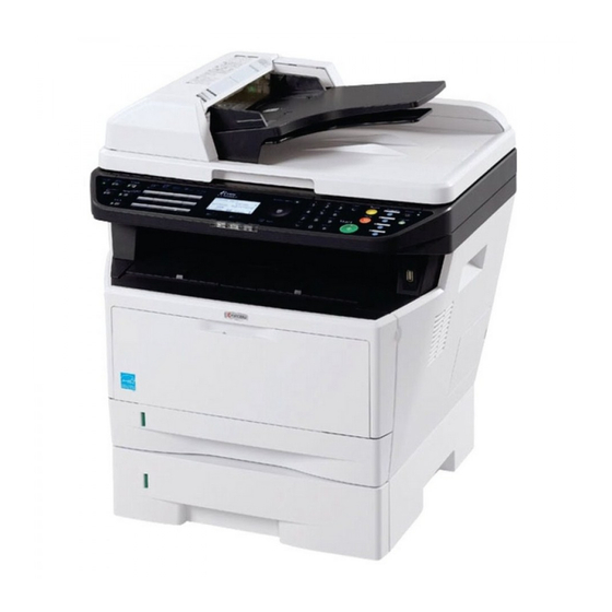
Page 15: Parts Names
1-1-2 Parts names (1) Overall Figure 1-1-1 Original cover Lock lever 17. MP (Multi-Purpose) tray Platen (contact glass) 10. Toner container 18. MP tray extension Original size Indicator plate 11. Top tray 19. USB Interface connector Operation panel 12. Paper length guide 20. - Page 16 (2) Operation panel Figure 1-1-2 System menu/Counter key 14. Function Menu key Status/Job Cancel key 15. Numeric keys Copy key 16. Clear key Address Book key 17. Reset key Address Recall key 18. Power key Confirm Destination key 19. Back key Add Destination key 20.
-
Page 17: Machine Cross Section
1-1-3 Machine cross section Paper path Paper path (option) Light path Figure 1-1-3 Cassette Laser scanner unit (LSU) MP tray Transfer/separation section Paper feed/conveying section 10. Fuser section Toner container 11. Exit section Developing unit 12. Duplex/conveying section Main charger unit 13. - Page 18 This page is intentionally left blank. 1-1-6...
-
Page 19: Installation Environment
1-2 Installation 1-2-1 Installation environment ° ° Temperature: 10 to 32.5 C/50 to 90.5 Humidity: 15 to 80%RH Power supply: 120 V AC, 7.4 A 220 - 240 V AC, 3.8 A ± ± Power source frequency: 50 Hz 0.3%/60 Hz 0.3% Installation location Avoid direct sunlight or bright lighting. -
Page 20: Unpacking
1-2-2 Unpacking Figure 1-2-2 Printer 10. Toner container Outer case 11. Plastic bag Inner frame 12. Power cord 13. Plastic bag (250 × 600) Bottom pad L Bottom pad R 14. Operation labels Machine cover 15. Operation label pad 16. Plastic bag (240 × 350) Top pad L Top pad R 17. -
Page 21: Removing The Tapes
(1) Removing the tapes <Procedure> 1. Remove two tapes. 1. Open the sheet. Tapes Sheet Figure 1-2-3 2. Open the original cover. 3. Remove the sheet. 4. Remove the paper. Sheet Original cover Paper Figure 1-2-4 1-2-3... - Page 22 5. Remove nine tapes. Tape Tapes Tapes Tapes Tapes Figure 1-2-5 1-2-4...
-
Page 23: Installing The Expansion Memory (Option)
1-2-3 Installing the expansion memory (option) <Procedure> 1. Turn off the main power switch. Caution: Do not insert or remove expansion memory while machine power is on. Doing so may cause damage to the machine and the expansion memory. 2. Remove the right side cover. 3. - Page 24 This page is intentionally left blank. 1-2-6...
-
Page 25: Maintenance Mode
1-3 Maintenance Mode 1-3-1 Maintenance mode The machine is equipped with a maintenance function which can be used to maintain and service the machine. (1) Executing a maintenance item Start Press the status key. Enter “10871087” using Maintenance mode is entered. the numeric keys. -
Page 26: Maintenance Modes Item List
(2) Maintenance modes item list Section Item Content of maintenance item Initial setting* General U000 Outputting an own-status report U001 Exiting the maintenance mode U002 Setting the factory default data U004 Displaying the machine number U019 Displaying the ROM version Initialization U021 Initializing counters and mode settings... - Page 27 Section Item Content of maintenance item Initial setting* Mode setting U250 Setting the maintenance cycle 100000 U251 Checking/clearing the maintenance count U252 Setting the destination U253 Switching between double and single counts U260 Selecting the timing for copy counting FEED U265 Setting OEM purchaser code U285...
-
Page 28: Contents Of The Maintenance Mode Items
(3) Contents of the maintenance mode items Maintenance Description item No. Outputting an own-status report U000 Description Outputs lists of the current settings of the maintenance items and paper jam and service call occurrences. Outputs the event log. Printing a report is disabled either when a job is remaining in the buffer or when [Pause All Print Jobs] is pressed to halt printing. - Page 29 Maintenance Description item No. Displaying the machine number U004 Description Displays the machine number. Purpose To check the machine number. Method Press the start key. The currently machine number is displayed. Completion Press the stop key. The screen for selecting a maintenance item No. is displayed. Displaying the ROM version U019 Description...
- Page 30 Maintenance Description item No. Initializing counters and mode settings U021 Description Initializes all settings, except those pertinent to the type of machine, namely each counter, service call history and mode setting. Also initializes backup RAM according to region specification selected in maintenance item U252 Setting the destination.
- Page 31 Maintenance Description item No. Checking motor operation U030 Description Drives each motor. Purpose To check the operation of each motor. Method 1. Press the start key. 2. Select the motor to be operated. 3. Press the start key. The operation starts. Display Operation MAIN...
- Page 32 Maintenance Description item No. Checking clutch operation U032 Description Turns each clutch on. Purpose To check the operation of each clutch. Method 1. Press the start key. 2. Select the clutch to be operated. 3. Press the start key. The clutch turns on. Display Clutches FEED CL...
- Page 33 Maintenance Description item No. Adjusting the print start timing U034 Description Adjusts the leading edge registration or center line. Purpose Make the adjustment if there is a regular error between the leading edges of the copy image and original. Make the adjustment if there is a regular error between the center lines of the copy image and original. Method 1.
- Page 34 Maintenance Description item No. Adjustment: Center line adjustment U034 1. Select the item to be adjusted. Display Description Setting Initial Change in range setting value per step LEFT Adjustment of reference value 0 to 1180 1 dot MP TRAY Paper feed from MP tray* -70 to 70 1 dot CASSETTE 1...
- Page 35 Maintenance Description item No. Adjusting the deflection in the paper U051 Description Adjusts the deflection in the paper. Purpose Make the adjustment if the leading edge of the copy image is missing or varies randomly, or if the copy paper is Z-folded.
- Page 36 Maintenance Description item No. Setting the adjustment of the motor speed U053 Description Performs fine adjustment of the speeds of the motor. Purpose To adjust the speed of the respective motor when the magnification is not correct. Method 1. Press the start key. 2.
- Page 37 Maintenance Description item No. Adjusting the shading position U063 Description Changes the shading position of the scanner. Purpose Used when white lines continue to appear longitudinally on the image after the shading plate is cleaned. This is due to flaws or stains inside the shading plate. To prevent this problem, the shading position should be changed so that shading is possible without being affected by the flaws or stains.
- Page 38 Maintenance Description item No. Adjusting the scanner magnification U065 Description Adjusts the magnification of the original scanning. Purpose Make the adjustment if the magnification in the main scanning direction is incorrect. Make the adjustment if the magnification in the auxiliary scanning direction is incorrect. Caution Adjust the magnification of the scanner in the following order.
- Page 39 Maintenance Description item No. Adjusting the scanner leading edge registration U066 Description Adjusts the scanner leading edge registration of the original scanning. Purpose Make the adjustment if there is a regular error between the leading edges of the copy image and original. Adjustment 1.
- Page 40 Maintenance Description item No. Adjusting the scanner center line U067 Description Adjusts the scanner center line of the original scanning. Purpose Make the adjustment if there is a regular error between the center lines of the copy image and original. Adjustment 1.
- Page 41 Maintenance Description item No. Adjusting the scanning position for originals from the DP U068 Description Adjusts the position for scanning originals from the DP. Performs the test copy at the four scanning positions after adjusting. Purpose Used when the image fogging occurs because the scanning position is not proper when the DP is used. Run U071 to adjust the timing of DP leading edge when the scanning position is changed.
- Page 42 Maintenance Description item No. Adjusting the DP magnification U070 Description Adjusts the DP original scanning speed. Purpose Make the adjustment if the magnification is incorrect in the auxiliary scanning direction when the optional DP is used. Method 1. Press the start key. 2.
- Page 43 Maintenance Description item No. Adjusting the DP scanning timing U071 Description Adjusts the DP original scanning timing. Purpose Make the adjustment if there is a regular error between the leading or trailing edges of the original and the copy image when the optional DP is used. Method 1.
- Page 44 Maintenance Description item No. Adjustment: Trailing edge registration U071 1. Press the system menu key. 2. Place an original on the DP and press the start key to make a test copy. 3. Press the system menu key. 4. Change the setting value using the cursor left/right keys. For copy example 1, increase the value.
- Page 45 Maintenance Description item No. Adjusting the DP center line U072 Description Adjusts the scanning start position for the DP original. Purpose Make the adjustment if there is a regular error between the centers of the original and the copy image when the optional DP is used.
- Page 46 Maintenance Description item No. Checking scanner operation U073 Description Simulates the scanner operation under arbitrary conditions. Purpose To check scanner operation. Start 1. Press the start key. 2. Select the item to be operated. Display Description SCANNER MOTOR Scanner operation HOME POSITION Home position operation DUST CHECK...
- Page 47 Maintenance Description item No. Setting DP reading position modification operation U087 Description The presence or absence of dust is determined by comparing the scan data of the original trailing edge and that taken after the original is conveyed past the DP original scanning position. If dust is identified, the DP original scanning position is adjusted for the following originals.
- Page 48 Maintenance Description item No. Outputting a MIP-PG pattern U089 Description Selects and outputs the MIP-PG pattern created in the machine. Purpose To check copier status other than scanner when adjusting image printing, using MIP-PG pattern output (with- out scanning). Method 1.
- Page 49 Maintenance Description item No. Setting the exposure density gradient U093 Description Changes the exposure density gradient in the manual density mode, depending on respective image quality modes. Purpose To set how the image density is altered by a change of one step in the manual density adjustment for respec- tive image quality modes.
- Page 50 Maintenance Description item No. Setting the main high voltage U100 Description Controls the main charger high voltage to optimize the surface potential. Purpose To change the setting value to adjust the image if an image failure (background blur, etc.) occurs. Setting 1.
- Page 51 Maintenance Description item No. Performing drum refresh operation U113 Description Executes drum refresh operation. Purpose To operate when a faulty image (black line, etc.) occurs. Method 1. Press the start key. 2. Select the item. Setting Initial Change in Display Description range setting...
- Page 52 Maintenance Description item No. Setting toner loading operation U144 Description Sets toner loading operation after completion of copying. Toner is forcibly evacuated in case the average print- ing ratio for the number of printed pages assigned by [PAGE] is lower than the ratio defined by [RATIO]. Purpose To set whether or not toner is loaded on the drum after low density copying.
- Page 53 Maintenance Description item No. Setting the fuser control temperature U161 Description Changes the fuser control temperature. Purpose Normally no change is necessary. However, can be used to prevent curling or creasing of paper, or solve a fuser problem on thick paper. Method 1.
- Page 54 Maintenance Description item No. Checking DP operation U203 Description Simulates the original conveying operation separately in the optional DP. Purpose To check the DP operation. Method 1. Press the start key. 2. Place an original in the DP if running this simulation with paper. 3.
- Page 55 Maintenance Description item No. Operation panel lock U223 Description Sets the operation panel lock function to ON or OFF. Purpose To restrict operation in the system menu on the operation panel. Setting 1. Press the start key. 2. Select the item. Display Description UNLOCK...
- Page 56 Maintenance Description item No. Checking the DP sensors U244 Description Displays the status of the respective sensors in the optional DP. Purpose To check if respective sensors in the optional DP operate correctly. Method 1. Press the start key. 2. Turn the respective sensors on and off manually to check the status. When a sensor is detected to be in the ON position, the display for that sensor will be highlighted.
- Page 57 Maintenance Description item No. Setting the destination U252 Description Switches the operations and screens of the machine according to the destination. Purpose To be executed after initializing the backup RAM, in order to return the setting to the value before replacement or initialization.
- Page 58 Maintenance Description item No. Selecting the timing for copy counting U260 Description Changes the copy count timing for the total counter and other counters. Purpose To be set according to user (copy service provider) request. If a paper jam occurs frequently in the optional document finisher when the number of copies is counted at the time of paper ejection, copies are provided without copy counts.
- Page 59 Maintenance Description item No. Setting the size conversion factor U332 Sets the coefficient of nonstandard sizes in relation to the A4/Letter size. The coefficient set here is used to convert the black ratio in relation to the A4/Letter size and to display the result in user simulation. Purpose To set the coefficient for converting the black ratio for nonstandard sizes in relation to the A4/Letter size.
- Page 60 Maintenance Description item No. Setting the value for maintenance due indication U345 Description Sets when to display a message notifying that the time for maintenance is about to be reached, by setting the number of copies that can be made before the current maintenance cycle ends. When the difference between the number of copies of the maintenance cycle and that of the maintenance count reaches the set value, the message is displayed.
- Page 61 Maintenance Description item No. Adjusting margins of image printing U402 Description Adjusts margins for image printing. Purpose Make the adjustment if margins are incorrect. Adjustment 1. Press the start key. 2. Select the item to be adjusted. Setting Initial Change in Display Description range...
- Page 62 Maintenance Description item No. Adjusting margins for scanning an original on the platen U403 Description Adjusts margins for scanning the original on the platen. Purpose Make the adjustment if margins are incorrect. Adjustment 1. Press the start key. 2. Select the item to be adjusted. Setting Initial Change in...
- Page 63 Maintenance Description item No. Adjusting margins for scanning an original from the DP U404 Description Adjusts margins for scanning the original from the DP. Purpose Make the adjustment if margins are incorrect when the optional DP is used. Caution Before making this adjustment, ensure that the following adjustments have been made in maintenance mode. U402 U403 U404...
- Page 64 Maintenance Description item No. Adjusting the scanner automatically U411 Description Uses a specified original and automatically adjusts the following items in the scanner and the DP scanning sections. Purpose To perform automatic adjustment of various items in the scanner and the DP scanning sections. Method 1.
- Page 65 Maintenance Description item No. Setting the target U425 Description Enters the lab values that is indicated on the back of the chart (P/N: 302FZ56990) used for adjustment. Purpose Performs data input in order to correct for differences in originals during automatic adjustment. Method 1.
- Page 66 Maintenance Description item No. U425 Left edge 30 mm 148.5 mm 267 mm Leading edge Black belt (b) 35 mm Black belt (a) 110 mm [MAIN ADJ] = ((A + C) / 2 + B) / 2 [SUB LEAD ADJ] = ((D + F) / 2 + E) / 2 [SUB TAIL ADJ] = G 185 mm...
- Page 67 Maintenance Description item No. Checking/clearing the paper jam counts U903 Description Displays or clears the jam counts by jam locations. Purpose To check the paper jam status. Also to clear the jam counts after replacing consumable parts. Method 1. Press the start key. 2.
- Page 68 Maintenance Description item No. Checking/clearing counts by optional devices U905 Description Displays or clears the counts of optional DP. Purpose To check the use of optional DP. Also to clear the counts after replacing consumable parts. Method 1. Press the start key. Display Description No.
- Page 69 Maintenance Description item No. Setting backup data reading/writing U917 Description Retrieves the backup data to a USB memory from the machine; or writes the data from the USB memory to the machine. Purpose To store and write data when replacing the control PWB. Method 1.
- Page 70 Maintenance Description item No. Checking the copy counts U920 Description Checks the copy counts. Purpose To check the copy counts. Method Press the start key. The current counts of copy counter, printer counter and fax counter are displayed. Completion Press the stop key. The screen for selecting a maintenance item No. is displayed. Clearing the all copy counts and machine life counts (one time only) U927 Description...
- Page 71 Maintenance Description item No. Data capture mode U977 Description Store the print data sent to the machine into USB memory. Purpose In case to occur the error at printing, check the print data sent to the machine. Method 1. Insert USB memory in USB memory slot. 2.
- Page 72 Maintenance Description item No. Outputting a VTC-PG pattern U993 Description Selects and outputs a VTC-PG pattern created in the machine. Purpose When performing respective image printing adjustments, used to check the machine status apart from that of the scanner with a non-scanned output VTC-PG pattern. Method 1.
-
Page 73: Paper Misfeed Detection
1-4 Troubleshooting 1-4-1 Paper misfeed detection (1) Paper misfeed indication When a paper misfeed occurs, the printer immediately stops printing and displays the paper misfeed message on the operation panel. To remove paper misfed in the printer, pull out the paper cassette, open the front cover, rear cover or duplexer’s cover, or remove the drum unit. -
Page 74: Self-Diagnostic Function
1-4-2 Self-diagnostic function (1) Self-diagnostic function This printer is equipped with self-diagnostic function. When a problem is detected, the printer stops printing and display an error message on the operation panel. An error message consists of a message prompting a contact to service personnel, total print count, and a four-digit error code indicating the type of the error. -
Page 75: Self Diagnostic Codes
(2) Self diagnostic codes Remarks Code Contents Causes Check procedures/corrective measures 0100 Backup memory device error Defective flash Replace the control PWB (See page 1-5- memory. 35). Defective control Replace the control PWB (See page 1-5- PWB. 35). 0110 Backup memory data error Defective flash Replace the control PWB (See page 1-5- memory. - Page 76 Remarks Code Contents Causes Check procedures/corrective measures 2000 Main motor error Defective harness Reinsert the connector. Also check for conti- The main motor ready input is not given between main nuity within the connector harness. If none, for 2 s during the main motor is ON. motor (CN1) and remedy or replace the harness (See page 1- control PWB...
- Page 77 Remarks Code Contents Causes Check procedures/corrective measures 3100 ISU home position error Defective FFC Reinsert the FFC. Also check for continuity between CCD within the FFC. If none, remedy or replace PWB (YC1) and the FFC. control PWB (YC8), or improper FFC insertion.
- Page 78 Remarks Code Contents Causes Check procedures/corrective measures 3200 Exposure lamp error Defective FFC Reinsert the FFC. Also check for continuity The exposure lamp is not turned on. between scanner within the FFC. If none, remedy or replace PWB (YC103) and the FFC.
- Page 79 Remarks Code Contents Causes Check procedures/corrective measures 3500 Communication error between scan- Defective FFC Reinsert the FFC. Also check for continuity between control within the FFC. If none, remedy or replace An error code is detected. PWB (YC8) and the FFC. CCD PWB (YC1), or improper FFC insertion.
- Page 80 Remarks Code Contents Causes Check procedures/corrective measures 6030 Broken fuser thermistor wire Poor contact in the Reinsert the connector (See page 1-5-30). Input from fuser thermistor is 0 (A/D fuser thermistor value). connector termi- nals. Broken fuser ther- Replace the fuser unit (See page 1-5-30). mistor wire.
- Page 81 Remarks Code Contents Causes Check procedures/corrective measures F020 Control PWB RAM checksum error Defective main Turn the main power switch off/on to restart memory (RAM) on the printer. If the error is not resolved, the control PWB. replace control PWB (See page 1-5-35). Defective Replace the expanded memory (DIMM).
-
Page 82: Image Formation Problems
1-4-3 Image formation problems (1)Completely blank (2)All-black printout. (3)Dropouts. (4)Black dots. (5)Black horizontal printout. streaks. See page 1-4-11 See page 1-4-11 See page 1-4-12 See page 1-4-12 See page 1-4-12 (6)Black vertical (7)Unsharpness. (8)Gray background. (9)Dirt on the top (10)Undulated print- streaks. -
Page 83: All-Black Printout
(1) Completely blank printout. Print example Causes Check procedures/corrective measures Connection failure with DP connector If a blank copy is made because the original loaded in the DP (Only when the option DP is installed) is not fed after the Start key is pressed: Turn the main power switch off, investigate the DP connector connection, and firmly connect the DP connector. -
Page 84: Dropouts
(3) Dropouts. Print example Causes Check procedures/corrective measures Defective developing roller (develop- If the defects occur at regular intervals of 62.8 mm/2 " (See ing unit). page 2-4-3), the problem may be the damaged developing roller (in the developing unit). Replace the developing unit (See page 1-5-25). -
Page 85: Black Vertical Streaks
(6) Black vertical streaks. Print example Causes Check procedures/corrective measures Adhesion of oxide to main charger Remove the drum unit (See page 1-5-26). Slide the charger wire. cleaner (green) left and right 2 or 3 times to clean the charger wire, then return it to its original position (CLEANER HOME POSITION). -
Page 86: Dirt On The Top Edge Or Back Of The Paper
(9) Dirt on the top edge or back of the paper. Print example Causes Check procedures/corrective measures Toner contamination in various parts. Dirty edges and back of the paper can be caused by toner accumulated on such parts as the paper chute guide, paper conveying paths, the bottom of the drum and developing unit, and the fuser unit inlet. -
Page 87: Electric Problems
1-4-4 Electric problems Problem Causes Check procedures/corrective measures (1)The machine does No electricity at the power Measure the input voltage. not operate when the outlet. main power switch is The power cord is not Check the contact between the power plug and the outlet. turned on. - Page 88 Problem Causes Check procedures/corrective measures (6)Paper feed clutch Broken paper feed clutch Check for continuity across the coil. If none, replace the paper does not operate. coil. feed clutch. Defective harness between Reinsert the connector. Also check for continuity within the con- paper feed clutch and con- nector harness.
- Page 89 Problem Causes Check procedures/corrective measures (12)A paper jam in A piece of paper torn from Check and remove if any. the paper feed/con- paper is caught around reg- veying section or istration sensor or exit sen- fuser section is indi- sor.
-
Page 90: Mechanical Problems
1-4-5 Mechanical problems Problem Causes/check procedures Corrective measures (1)No primary paper Check if the surfaces of the paper feed roller Clean with isopropyl alcohol. feed. is dirty with paper powder. Check if the paper feed roller is deformed. Check visually and replace any deformed paper feed roller (assembly) (See page 1-5- Defective paper feed clutch installation. -
Page 91: Assembly And Disassembly
1-5 Assembly and Disassembly 1-5-1 Precautions for assembly and disassembly (1) Precautions Before starting disassembly, press the Power key on the operation panel to off. Make sure that the Power lamp is off before turning off the main power switch. And then unplug the power cable from the wall outlet. When the fax kit is installed, be sure to disconnect the modular code before starting disassembly. -
Page 92: How To Tell A Genuine Kyocera Mita Toner Container
A black-colored band when seen through the left side window ( A shiny or gold-colored band when seen through the right side window ( The above will reveal that the toner container is a genuine Kyocera Mita branded toner container, otherwise, it is a coun- terfeit. -
Page 93: Outer Covers
1-5-2 Outer covers (1) Detaching and refitting the left cover and right cover Procedure 1. Remove the screw. 2. Unhook four hooks and then remove the Hook rear upper cover. Rear upper cover Hook Hook Hook Rear upper cover Screw Figure 1-5-3 3. - Page 94 7. Unhook seven hooks and then remove the right cover. Hook Hook Hook Hook Hook Hook Hook Right cover Right cover Right cover Figure 1-5-5 1-5-4...
- Page 95 8. Unhook six hooks and then remove the left cover. Hook Hook Hook Hook Hook Hook Left cover Left cover Left cover Figure 1-5-6 1-5-5...
-
Page 96: Paper Feed Section
1-5-3 Paper feed section (1) Detaching and refitting the paper feed assembly (paper feed roller and pickup roller) Procedure 1. Remove the cassette. Cassette Figure 1-5-7 2. Slide the feed shaft. 3. While pressing the lever and then remove the paper feed roller assembly. Feed shaft Paper feed roller assembly... - Page 97 4. Check or replace the paper feed assembly Paper feed roller and refit all the removed parts. Feed shaft assembly When refitting the paper feed roller assem- bly, be sure to align the paper feed roller pivot with the slotted hole on the feed shaft. Paper feed roller assembly Feed shaft...
-
Page 98: Detaching And Refitting The Retard Roller Assembly
(2) Detaching and refitting the retard roller assembly Procedure 1. Remove the cassette (See page 1-5-6). Retard guide 2. Push the bottom plate down until it locks. Hook 3. Unhook two hooks and then remove the retard guide. Hook Cassestte Bottom plate Retard guide Cassette... - Page 99 5. Check or replace the retard roller assembly and refit all the removed parts. Retard roller assembly Caution: Before refitting the retard roller assembly, firmly install the spring onto the projection of the retard roller assembly. Projection Spring Figure 1-5-12 1-5-9...
-
Page 100: Detaching And Refitting The Mp Paper Feed Roller
(3) Detaching and refitting the MP paper feed roller Procedure 1. Open the front cover. 2. Pull the MP feed holder (lever) down. 3. Slide the MP feed holder. 4. Remove the MP paper feed roller. MP paper feed roller Front cover MP paper feed roller MP feed holder... - Page 101 5. Check or replace the MP paper feed roller and refit all the removed parts. Pivot When refitting the MP paper feed roller, be sure to align the paper feed roller pivot with the slotted hole on the MPF feed shaft. When refitting the MP paper feed roller, be sure to align the MPF feed shaft pivot with the slotted hole on the MP paper feed roller.
-
Page 102: Optical Section
1-5-4 Optical section (1) Detaching and refitting the original holder Procedure 1. Pull the original holder out. Original cover Figure 1-5-15 1-5-12... -
Page 103: Detaching And Refitting The Scanner Unit
(2) Detaching and refitting the scanner unit. Procedure 1. Remove the original holder (See page 1-5- 12). Control PWB 2. Remove the left cover and right cover (See page 1-5-3). 3. Remove the FFC and connector from the control PWB. 4. - Page 104 5. Release three clamps and then remove the wires. Wires Clamp Wires Clamp Clamp Figure 1-5-17 6. Remove two screws. Screw Screw Screw Screw Screw Figure 1-5-18 1-5-14...
- Page 105 7. Unhook four hooks and then remove the Scanner unit scanner unit. Hooks Hooks Figure 1-5-19 1-5-15...
-
Page 106: Detaching And Refitting The Laser Scanner Unit (Lsu)
(3) Detaching and refitting the laser scanner unit (LSU) Procedure 1. Remove the scanner unit (See page 1-5- Control PWB 13). 2. Remove the screw and then remove the grounding terminal. 3. Remove two connectors from the control PWB. Connector Connector YC10 Grounding... - Page 107 4. Remove the wires from three clamps. 5. Remove the connector from the power Clamp source PWB. Clamps Power source Power source YC106 Connector Figure 1-5-21 6. Unhook four hooks and then remove the frame left duct. 7. Remove the wires from the clamp. Frame left duct Hook Hook...
- Page 108 8. Remove the stopper and then remove the top cover rack-L from the top cover. Top cover Top cover rack-L Top cover rack-L Top cover Stopper Figure 1-5-23 9. Remove four screws from the top cover. Screw Top cover Screw Screw Screw Figure 1-5-24...
- Page 109 10. Unhook two hooks and then remove the top cover. 11. Remove the connector. Hook Hook Top cover Connector Figure 1-5-25 12. Release the clamp and then pull out the Screws wires. 13. Remove four screws and then remove the Screws laser scanner unit (LSU).
-
Page 110: Detaching And Refitting The Image Scanner Unit (Isu)
(4) Detaching and refitting the image scanner unit (ISU) Procedure 1. Remove the original holder (See page 1-5- 12). 2. Unhook two hooks by using flat screwdriver Operation unit from the pits and then detach the operation unit. 3. Remove the connector and then remove the operation unit. - Page 111 4. Remove two screws. Screw 5. Unhook three hooks and then remove the Original holder cover original holder cover. Screw Hooks Figure 1-5-28 6. Move the image scanner unit (ISU) unit to the center. Holder 7. Detach the ISU shaft from the holder by lift- ISU shaft ing it.
- Page 112 9. Remove the ISU shaft. 10. Remove the ISU belt from the hooks of the ISU. ISU belt 11. Pull the ISU shaft out from the ISU unit. 12. Check or replace the image scanner unit (ISU) and refit all the removed parts. Hook Hook Image...
-
Page 113: Detaching And Refitting The Exposure Lamp And Inverter Pwb
(5) Detaching and refitting the exposure lamp and inverter PWB Procedure 1. Remove the original holder (See page 1-5- 12). 2. Move the image scanner unit (ISU) unit to Image scanner the center. unit (ISU) 3. Unhook five hooks and then remove the lamp mount. - Page 114 Inverter PWB 5. Remove the connector. 6. Remove the screw and then remove the Connector inverter PWB. Screw 7. Check or replace the inverter PWB and refit all the removed parts. Caution: Replace F1 with a fuse rated 250 V ac, 0.75 A, non-time delay, (when F1 fuse is replaced.) Inverter PWB...
-
Page 115: Developing Section
1-5-5 Developing section (1) Detaching and refitting the developing unit Procedure 1. Open the front cover. 2. Remove the developing unit. 3. Check or replace the developing unit and refit all the removed parts. Developing unit Front cover Figure 1-5-35 1-5-25... -
Page 116: Drum Section
1-5-6 Drum section (1) Detaching and refitting the drum unit Procedure 1. Remove the developing unit (See page 1-5- 25). 2. Remove the drum unit. 3. Check or replace the drum unit and refit all the removed parts. Drum unit Figure 1-5-36 1-5-26... -
Page 117: Detaching And Refitting The Main Charger Unit
(2) Detaching and refitting the main charger unit Procedure 1. Remove the developing unit (See page 1-5- 25). 2. Remove the drum unit (See page 1-5-26). 3. Remove the tape. Tape 4. While pushing on the main plate , slide Main charger unit the main charger unit Drum unit... -
Page 118: Transfer/Separation Section
1-5-7 Transfer/separation section (1) Detaching and refitting the transfer roller Procedure 1. Remove the developing unit (See page 1-5- 25). 2. Remove the drum unit (See page 1-5-26). 3. Slide the paper chute guide and unhook the hooks. 4. Remove the paper chute guide. Paper chute guide Paper chute guide Hook... - Page 119 5. Remove the transfer roller’s shaft from the Shaft both transfer bushes. 6. Remove the gear Z16 from the transfer roller. Transfer roller Shaft Transfer bush Transfer bush Transfer roller Gear Z16 Figure 1-5-40 7. Check or replace the transfer roller and refit all the removed parts.
-
Page 120: Fuser Section
1-5-8 Fuser section (1) Detaching and refitting the fuser unit Procedure 1. Remove the left cover and right cover (See page 1-5-3). Clamp 2. Remove the wires from three clamps. 3. Remove the connector from the power source PWB. Clamps Power source YC105 Power source... - Page 121 6. Remove the connector from the power source PWB. Connector YC102 Power source PWB Connector Figure 1-5-44 7. Remove the connector from the control PWB. Control PWB Connector Figure 1-5-45 1-5-31...
- Page 122 8. Remove the rear cover. Rear cover Figure 1-5-46 9. Remove two screws and then remove the fuser unit. Screw Fuser unit Screw Figure 1-5-47 1-5-32...
- Page 123 10. Check or replace the fuser unit and refit all the removed parts. Caution: When reinstalling the fuser unit, tighten up a screw while pressing the fuser Fuser unit unit in order of 1 to 2. Screw Fuser unit Screw Figure 1-5-48 1-5-33...
-
Page 124: Switching The Fuser Pressure
(2) Switching the fuser pressure The fuser pressure may be decreased to suppress the print quality problems such as paper creases and curls. It must be cautioned that decreasing the fuser pressure could cause loose toner fusing. Procedure 1. Remove the cassette (See page 1-5-6). 2. -
Page 125: Pwbs
1-5-9 PWBs (1) Detaching and refitting the control PWB Procedure 1. Remove the right cover (See page 1-5-3). 2. Remove the five connectors from the scan- YC109 ner PWB. YC104 YC108 3. Remove twenty one connectors and two FFCs form the control PWB. 4. - Page 126 5. Remove six screws and two grounding ter- Screw minal. Screw Grouniding terminal Screw Screw Grouniding terminal Screw Control PWB assembly Screws Figure 1-5-51 6. Unhook the hook and then remove the con- Hook trol PWB assembly. Control PWB assembly Control PWB assembly Figure 1-5-52 1-5-36...
- Page 127 7. Remove five screws and then remove the Control PWB control PWB. Screw 8. Check or replace the control PWB and refit Screw all the removed parts. Screw To replace the control PWB, remove the EEPROM (U17) from the old control PWB and mount it to the new control PWB.
-
Page 128: Detaching And Refitting The Power Source Pwb
(2) Detaching and refitting the power source PWB Procedure 1. Remove the left cover (See page 1-5-3). 2. Remove the wires from three clamps. 3. Remove five connectors from the power Clamp source PWB. Clamps Power source Connectors YC107 YC105 Power source YC108 YC106... - Page 129 6. Remove the screw and then detach the inlet mount. Screw Inlet mount Figure 1-5-56 7. Remove five screws. 8. Remove three connectors and then remove the power source PWB assembly. Connector Connector Connector Screw Screw Screw Power source PWB assembly Power source PWB Screws Connector...
- Page 130 9. Remove four screws and then remove the Screw Screw power source PWB from the power source PWB plate. Power source PWB 10. Check or replace the power source PWB and refit all the removed parts. Screws Caution: The power source PWB sheet must be installed in the specified position.
-
Page 131: Detaching And Refitting The High Voltage Pwb
(3) Detaching and refitting the high voltage PWB Procedure 1. Remove the developing unit (See page 1-5- 25). 2. Remove the drum unit (See page 1-5-26). 3. Remove the cassette (See page 1-5-6). 4. Remove the left cover and right cover (See page 1-5-3). - Page 132 11. Remove four screws. 12. Unhook three hooks and then remove the lower base cover. Screws Screws Lower base cover Hook Hook Hook Figure 1-5-61 1-5-42...
- Page 133 13. Remove the spring. 14. Remove the cassette pin. Spring Cassette pin Cassette pin Figure 1-5-62 15. Remove two connectors and then remove the high voltage PWB. 16. Remove the cassette pin holder from the high voltage PWB. Connectors High voltage PWB High voltage PWB Cassette pin holder...
- Page 134 17. Check or replace the high voltage PWB and refit all the removed parts. High voltage PWB When refitting the high voltage PWB, be careful about following points. - Position the ground plate so that it is atop the high voltage PWB. Grounding - Each interface is firmly in contact with each plate...
-
Page 135: Detaching And Refitting The Scanner Pwb
(4) Detaching and refitting the scanner PWB Procedure 1. Remove the right cover (See page 1-5-3). 2. Remove six connectors and the FFC from the scanner PWB. YC109 YC104 YC108 YC103 YC102 YC101 YC105 Connectors FFCs Scanner PWB Scanner PWB Figure 1-5-65 3. -
Page 136: Others
1-5-10 Others (1) Detaching and refitting the main motor Procedure 1. Remove the right cover (See page 1-5-3). 2. Remove the connector. 3. Remove the M3 screw and two M4 screws. 4. Remove the main motor. 5. Check or replace the main motor and refit all the removed parts. -
Page 137: Direction Of Installing The Left Cooling Fan Motor, Right Cooling Fan Motor And Power Source Fan Motor
(2) Direction of installing the left cooling fan motor, right cooling fan motor and power source fan motor When detaching or refitting a fan motor, be careful of the airflow direction (intake or exhaust). Right cooling fan motor Intake Left cooling fan motor Exhaust Exhaust Power source... - Page 138 This page is intentionally left blank. 1-5-48...
-
Page 139: Upgrading The Firmware
1-6 Requirements on PWB Replacement 1-6-1 Upgrading the firmware Follow the procedure below to upgrade the firmware of control PWB (main controller and engine) and scanner PWB. Preparation Extract the file that has the download firmware and put them in the USB Memory. Procedure 1. -
Page 140: Remarks On Control Pwb Replacement
1-6-2 Remarks on control PWB replacement When replacing the control PWB, remove the EEPROM (U17) from the control PWB that has been removed and then reattach it to the new control PWB. EEPROM Control PWB EEPROM Figure 1-6-2 1-6-2... -
Page 141: Paper Feed/Conveying Section
2-1 Mechanical Construction 2-1-1 Paper feed/conveying section Paper feed/conveying section consists of the paper feed unit that feeds paper from the cassette and the MP tray paper feed unit that feeds paper from the MP tray, and the paper conveying section that conveys the fed paper to the transfer/ separation section. -
Page 142: Mp Tray Paper Feed Section
(2) MP tray paper feed section Figure 2-1-3 MP tray paper feed section MP paper feed roller MPF frame MPF separation pad MPF guide R/L MPF separator (10) MPF base MPF bottom plate (11) MPF middle tray MPF friction pad (12) MPF upper tray MP paper sensor (13) MPF turn guide... -
Page 143: Paper Conveying Section
(3) Paper conveying section Figure 2-1-5 Paper conveying section Lower registration roller Upper registration roller Registration sensor Actuator (registration sensor) Feed pulley Control PWB MMOTRDYN YC17-3 MOTCLK YC17-4 Main motor REMOTEN YC17-5 REGDRN Registration YC20-2 clutch High voltage PWB Registration REGN sensor YC23-11... -
Page 144: Drum Section
2-1-2 Drum section (1) Drum section The durable layer of organic photoconductor (OPC) is coated over the aluminum cylinder base. The OPC tend to reduce its own electrical conductance when exposed to light. After a cyclic process of charging, exposure, and development, the electrostatic image is constituted over the OPC layer. -
Page 145: Main Charger Unit
(2) Main charger unit As the drum rotates in a “clean (neutral)” state, its photoconductive layer is given a uniform, positive (+) corona charge dis- persed by the main charger wire. Due to high-voltage scorotron charging, the charging wire can get contaminated by oxi- dization after a long run. -
Page 146: Optical Section
2-1-3 Optical section (1) Scanner unit Figure 2-1-10Scanner unit ISU belt ISU top frame ISU shaft ISU bottom frame ISU gear 63/32 Contact glass ISU motor DP contact glass (10) Image scanner unit (ISU) Size indicator plate 2-1-6... - Page 147 (2) Image scanner unit (ISU) The image scanner unit consists of an exposure lamp, four mirrors, a lens, a CCD PWB, and so on. Also an inverter PWB for driving the exposure lamp and a home position sensor for detecting the home position of the image scanner unit are incorporated.
- Page 148 Original Contact glass Image scanner unit (ISU) Exposure Control CCD PWB lamp Inserter Mirrors and lens Scanner image sensor LAMP HPSW Home position sensor SCMOT1A, SCMOT2B SCMOT1B, SCMOT2A motor Scanner unit Figure 2-1-12 Scanner unit block diagram 2-1-8...
-
Page 149: Laser Scanner Unit
(3) Laser scanner unit The charged surface of the drum is then scanned by the laser beam from the laser scanner unit. The laser beam (780 nm wavelength) beam is dispersed as the polygon motor revolves to reflect the laser beam over the drum. - Page 150 Figure 2-1-14 Laser scanner unit Polygon motor (mirror) Laser diode (APC PWB) Collimator lens Cylindrical lens F-θ lens F-θ lens PD mirror SOS lens Pin photo diode sensor (PD PWB) (10) LSU mirror 2-1-10...
-
Page 151: Developing Section
2-1-4 Developing section The latent image constituted on the drum is developed into a visible image. The developing roller contains a 3-pole (S-NS) magnet roller and an aluminum cylinder rotating around the magnet roller. Toner attracts to the magnet sleeve since it is powdery ink made of black resin bound to iron particles. -
Page 152: Transfer/Separation Section
2-1-5 Transfer/separation section The transfer/separation section consists of the transfer roller, discharger brush and paper chute guide. A high voltage gen- erated by the high voltage PWB is applied to the transfer roller for transfer charging. Paper after transfer is separated from the drum. -
Page 153: Cleaning Section
2-1-6 Cleaning section After the transferring process, the drum needs to be physically cleaned of toner which is residual after the development process. The cleaning blade is constantly pressed against the drum and scrapes the residual toner off to the sweep roller. The waste toner is collected at the output end of the sweep roller and sent back to the toner container, into the waste toner reservoir. -
Page 154: Fuser Section
2-1-7 Fuser section The toner on the paper is molten and pressed into the paper as it passes between the heat roller and the press roller in the fuser unit. The heat roller has a heater lamp inside which continuously turns on and off by the fuser thermistor to maintain the constant temperature onto the heat roller surface. - Page 155 Fuser unit High Power Control PWB voltage source PWB Fuser thermal cutout HEATN YC103-6 YC23-5 YC102-1 SLEEP YC103-7 YC23-6 ZCROSS YC102-3 YC103-8 YC23-3 Fuser heater lamp Fuser thermistor THERM YC23-16 Figure 2-1-22 Fuser unit block diagram 2-1-15...
-
Page 156: Paper Exit Section
2-1-8 Paper exit section The paper exit section transports the paper which passed the fuser unit towards the top tray. The paper which passed through the fuser unit turns on the actuator (exit sensor) in the fuser unit, and is led by the guide comprised of the rear cover, frame and the FD cover guide, finally reaching the upper FD roller. - Page 157 Fuser unit Control PWB EXITN YC19-3 Exit sensor Figure 2-1-24 Paper exit section block diagram 2-1-17...
-
Page 158: Duplex/Conveying Section
2-1-9 Duplex/conveying section The duplex/conveying section consists of conveying path which sends the paper sent from the exit section to the paper feed/conveying section when duplex printing. Figure 2-1-25 Duplex/conveying section DU cover B DU holder Middle pulley B DU roller DU cover A Lower base cover Feed roller... -
Page 159: Electrical Parts Layout
2-2 Electrical Parts Layout 2-2-1 Electrical parts layout (1) PWBs Machine left Machine inside Machine right Figure 2-2-1 PWBs Control PWB ..........Main controller: Controls the software such as the print data processing and provides the interface with computers. Engine: Controls printer hardware such as high voltage/bias output con- trol, paper conveying system control, and fuser temperature control, etc. -
Page 160: Switches And Sensors
(2) Switches and sensors Machine left Machine inside Machine right Figure 2-2-2 Switches and sensors Main power switch ........Turns ON/OFF the AC power source. Interlock switch ..........Shuts off 24 V DC power line when the front cover is opened. Cassette switch.......... -
Page 161: Other Electrical Components
(3) Other electrical components Machine left Machine inside Machine right Figure 2-2-3 Other electrical components Main motor ............Drives the paper feed/conveying section and fuser unit. Polygon motor........... Drives the polygon mirror. ISU motor............Drives the ISU. Right cooling fan motor ........Cools the interior of machine. Left cooling fan motor ........ - Page 162 This page is intentionally left blank. 2-2-4...
-
Page 163: Power Source Pwb
2-3 Operation of the PWBs 2-3-1 Power source PWB +24V1 Scanner Power source PWB +24V1 Power source fan motor +24V1 Left cooling fan motor Zero cross Main power switch signal circuit +24V1 AC input Switching +24V2 regulator circuit Interlock switch SLEEP ZCROSS Fuser heater... - Page 164 Connector Signal Voltage Description YC101 NEUTRAL 120 V AC AC power input Connected 220 - 240 V AC to the AC LIVE 120 V AC AC power input inlet 220 - 240 V AC YC102 LIVE 120 V AC Fuser heater lamp output Connected 220 - 240 V AC to the fuser...
-
Page 165: Control Pwb
2-3-2 Control PWB Clutches Scanner PWB CCD PWB Solenoids Eraser lamp (PWB) APC PWB Engine control Commu- Image section nication control High voltage PWB section section Optional paper feeder Main control section Control PWB Operation panel Sensors motors Figure 2-3-3 Control PWB block diagram 2-3-3... - Page 166 2 31 YC28 YC29 YC11 YC19 Figure 2-3-4 Control PWB silk-screen diagram 2-3-4...
- Page 167 Connector Signal Voltage Description +12V 12 V DC 12 V DC power source Connected Ground to the scan- HPSW 0/3.3 V DC Home position sensor: On/Off ner PWB Ground Not used LAMP 0/24 V DC Exposure lamp drive signal Ground Connected PANCTS 0/3.3 V DC (pulse) Transmitting enable signal...
- Page 168 Connector Signal Voltage Description Ground Connected +3.3V1 3.3 V DC 3.3 V DC power source to the scan- CPUCLK 0/3.3 V DC (pulse) Serial communications clock signal ner PWB CPUSI 0/3.3 V DC (pulse) Serial communications data input CPUSO 0/3.3 V DC (pulse) Serial communications data output CPUSEL 0/3.3 V DC Communications select signal...
- Page 169 Connector Signal Voltage Description YC20 +24V3 24 V DC 24 V DC power source Connected REGDRN 0/24 V DC Registration clutch: On/Off to the regis- +24V3 24 V DC 24 V DC power source tration FEDDRN 0/24 V DC Paper feed clutch: On/Off clutch, +24V3 24 V DC...
- Page 170 Connector Signal Voltage Description YC28 ERASER 0/24 V DC Eraser lamp: On/Off Connected ERASRW 24 V DC 24 V DC power source to the eraser lamp YC29 DUDR1 0/24 V DC Duplex solenoid (activate): On/Off Connected COMMON 24 V DC 24 V DC power source to the DUDR2...
-
Page 171: Scanner Pwb
2-3-3 Scanner PWB Image scanner Optional document DP timing DP original unit (ISU) processor (DP) Exposure lamp sensor sensor paper DP switchback DP switchback paper feed Home pressure open/close feedshift feed clutch position Inverter solenoid sensor solenoid motor sensor Driver motor Driver CCD PWB... - Page 172 YC104 YC108 YC106 YC103 YC105 YC107 Figure 2-3-6Scanner PWB silk-screen diagram Connector Signal Voltage Description YC101 +24V1 24 V DC 24 V DC power source Connected N.C. Not used to the power Ground source PWB YC102 SEGIR 0/3.3 V DC Serial communications interruption demand Connected SSDIR...
- Page 173 Connector Signal Voltage Description YC105 +3.3V1 3.3 V DC 3.3 V DC power source Connected Ground to the TIMSWN 0/3.3 V DC DP timing sensor: On/Off optional DP ORGSWN 0/3.3 V DC DP original sensor: On/Off (DP driver OPSWN 0/3.3 V DC DP open/close sensor: On/Off PWB) DPDETN...
- Page 174 This page is intentionally left blank. 2-3-12...
-
Page 175: Appendixes
2-4 Appendixes 2-4-1 Appendixes (1) Wiring diagram 2-4-1... - Page 176 2-4-2...
-
Page 177: Repetitive Defects Gauge
(2) Repetitive defects gauge First occurrence of defect [24.99 mm/1"] Upper registration roller [37.68 mm/1 "] Lower registration roller [45.216 mm/1 "] Transfer roller [62.8 mm/2 "] Developing roller (developing unit) [73.162 mm/2 "] Heat roller (fuser unit) [78.5 mm/3 "] Press roller (fuser unit) 1/16 [94 mm/3... - Page 178 This page is intentionally left blank. 2-4-4...
Need help?
Do you have a question about the KM-2810 and is the answer not in the manual?
Questions and answers