
Related Manuals for RGBlink CP 3072PRO


Summary of Contents for RGBlink CP 3072PRO
- Page 1 CP 3072PRO USER MANUAL USER MANUAL Article No: RGB-RD-UM-3072PRO E001 Revision No: V1.2...
-
Page 2: Table Of Contents
3.4.6 Scale and Crop the Layer ....................28 3.4.7 DSK Setting ......................... 28 3.4.8 BLEND Setting ........................29 3.4.9 Mask Setting ........................29 3.4.10 Transitions Setting ......................30 3.4.11 Custom LOGO ........................31 3.4.12 Custom OSD ........................31 3.4.13 Custom STILL ........................32 CP 3072PRO User Manual... - Page 3 6.3.1 Installing Software ......................57 6.3.2 Set the OSD ......................... 59 6.3.3 Set the Effect ........................60 6.3.4 Set the Logo ........................61 6.3.5 Set the Still ......................... 62 6.4 Terms & Definitions ........................63 6.5 Revision History ..........................67 CP 3072PRO User Manual...
-
Page 4: Declarations
RGBlink. If the purchaser or a third party carries out modifications or repairs on goods delivered by RGBlink, or if the goods are handled incorrectly, in particular if the systems are commissioned operated incorrectly or if, after the transfer of risks, the goods are subject to influences not agreed upon in the contract, all guarantee claims of the purchaser will be rendered invalid. -
Page 5: Operators Safety Summary
Installation Safety Summary Safety Precautions For all CP 3072PRO processor installation procedures, please observe the following important safety and handling rules to avoid damage to yourself and the equipment. To protect users from electric shock, ensure that the chassis connects to earth via the ground wire provided in the AC power Cord. -
Page 6: Site Preparation
Site Preparation The environment in which you install your CP 3072PRO should be clean, properly lit, free from static, and have adequate power, ventilation, and space for all components. -
Page 7: Chapter 1 Your Product
Chapter 1 Your Product 1.1 In the Box Network Cable HDMI to DVI Warranty Card Screw Driver Cable & USB Files Antistatic Bag QC Declaration Note: USB is contained on the Warranty/Registration Card. Please keep. CP 3072PRO User Manual... -
Page 8: Product Overview
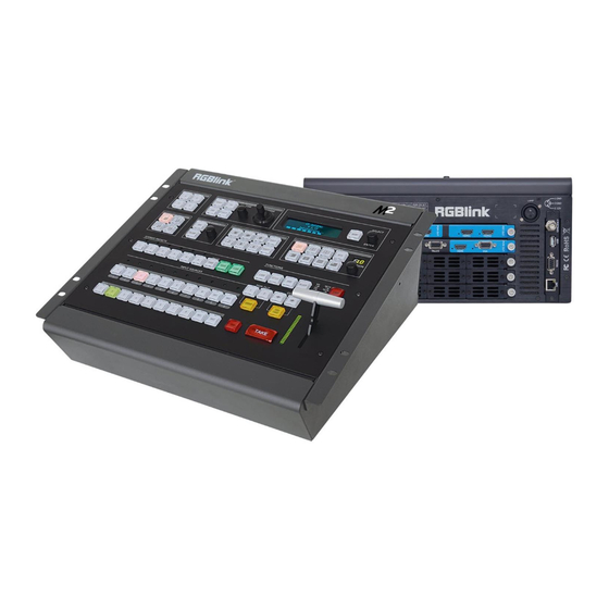
CP 3072PRO redefines modern hands on scaling and mixing for any environment. Totally modular and flexible in configuration, CP 3072PRO is packed with standard features to impress and present with ease. -
Page 9: Back Panel
BNC – 3G-SDI Each SDI module supports 1 SDI input and 1 SDI loop out. Standard 3G-SDI signals can input. And can connect to the SDI input of the next CP 3072PRO or the device with SDI input. CP 3072PRO... -
Page 10: Power Connection
For custom LOGO, OSD, STILL and MASK saving, and can be loaded. RS-232 Used for device upgrade. RJ45–Ethernet Used for device upgrade. Power Connection Power Switch Illuminated power switch. IEC – Power Input Main power input AC 85-264V Max 65W. CP 3072PRO User Manual... -
Page 11: Front Panel
This button used for position adjusting. If image quality distorts by improper operation, it can be recover by reset. Screen parameters setting button. Push the button, its LED light turns on, user can choose full size or screen size. FREEZE CP 3072PRO User Manual... - Page 12 Multiview mode selection, the button light is lit when selected, mainly for layout setting quickly in multiview. : 1P : PIP CENT : 3P. : CP 3072PRO V1.2 can not support this function. Stored Presets Area CP 3072PRO User Manual...
- Page 13 Displays current status of the product, and for feature selections provides interactive choices in conjunction with buttons on the front panel. Layer Mask Area Layer Mask Selection Layer mask selection button are shown as follows: : Heart CP 3072PRO User Manual...
- Page 14 Display the transition time. DURATION Knob Adjust transition time. The adjustment range is between 0S~9.9S. Functions Area LOGO Enable or disable the LOGO function. If select “ON”, user can set the X and Y, or load file from UDisk. CP 3072PRO User Manual...
- Page 15 GROUP: Effects switching for PGM1 or PGM2 at the same time. OSD Edit Area : Subtitle rows back button. : Subtitle rows forward button. OSD TAKE Subtitles switch button. Switch Modes Area Seamless switching. TAKE Seamless switching with effect. T-BAR WIPE and mix switching. CP 3072PRO User Manual...
-
Page 16: Dimension
Chapter 1: Your Product 1.2.3 Dimension Following is the dimension of CP 3072PRO for your reference: CP 3072PRO User Manual... -
Page 17: Chapter 2 Installing Your Product
OLED display will show as below, completing initialization before loading last settings and input/output configuration. On delivery, HDMI will be the default input signal, and the output format is defaulted to 1920x1080x60. CP 3072PRO V 1.22 Initializing... CP 3072PRO User Manual... - Page 18 Chapter 2: Installing Your Product PST Input : HDMI Output Format: 1920×1080×60 SN: 0009 Version: 1.22 CP 3072PRO User Manual...
-
Page 19: Chapter 3 Using Your Product
Turn the rotary knob to navigate to the menu item required. The option turns to green shows the current item. Push the knob to select and enter into the menu item. As shown in the figure below: CP 3072PRO User Manual... -
Page 20: Understanding The Menu Structure
Chapter 3: Using Your Product 3.2 Understanding the MENU Structure The MENU structure is shown in the figure below: CP 3072PRO User Manual... -
Page 21: Using The Menu
Chapter 3: Using Your Product 3.3 Using the Menu Use the menu system for convenient and intuitive operation. CP 3072PRO OLED display shows the menu items. The OLED display will show the default state when the menu is not in use, or the operation has timed out. -
Page 22: Input Menu
If select HDMI, HActive, VActive and Freq can be set. If select USB, file number, play mode, duration of picture, order, play state can be set. User can also select if upgrade by USB. 3.3.4 Output Menu ->Format 1920×1080×60 Custom Format >> 4K1K >> Color Space/Sample/Bit >> CP 3072PRO User Manual... -
Page 23: Background Menu
Set the format of external sync. 3.3.5 Background Menu ->Background 1 In 3-3 SDI Background 1 File 1 Background 1/2 Select input or picture. Background 1 Background 1/2 ~Background 2 Select the input signal for background1/2. Input BK1/2 Control CP 3072PRO User Manual... -
Page 24: Advance Menu
Select LOGO 1 or LOGO 2. ON/OFF Enable or disable the LOGO function. Set the X position of the LOGO. LOGO Set the Y position of the LOGO. Delete Delete the selected LOGO. Load File From UDisk CP 3072PRO User Manual... - Page 25 Enable or disable the Still function. Set the X position of the still. Still Set the Y position of the Still. Delete Delete the still. Load File From UDisk Select if load file from UDisk. Layer Blending Select the layer. CP 3072PRO User Manual...
-
Page 26: Language Menu
The adjustment range is between 0~255. Select “ON” or “OFF” to enable or disable DSK function. 3.3.7 Language Menu ->Language/语言 English Language/语言 Select Chinese or English. 3.3.8 System Menu ->Version >> Ethernet >> T-BAR Calibration >> Test >> CP 3072PRO User Manual... -
Page 27: Factory Reset Menu
->Factory Reset >> Factory Reset, Save IP >> Factory Reset Select “YES” or “NO”. Select “YES” to restore default settings. Factory Reset, Select “YES” or “NO”. Select “YES” to restore default settings, but keep the Save IP CP 3072PRO User Manual... -
Page 28: Pst Mode
Chapter 3: Using Your Product 3.4 PST Mode CP 3072PRO supports 2 HDMI preview output, and it supports the functions as below: 3.4.1 Signal Selection Push any button in Input Sources Area, for example, push the button [5], the border of signal 5 will change to yellow, and the signal in PGM monitor will be changed to signal 5. -
Page 29: Scale And Crop The Layer
<Advance>, push the knob to confirm. (Or push the [DSK] button to enter to the DSK menu items) ->Layer Layer 1 Preset Black BackGround Mode Key In Alpha ->Red Min Red Max Green Min Green Max ->Blue Min Blue Max CP 3072PRO User Manual... -
Page 30: Blend Setting
2. Turn the rotary knob, and select <Mask> option in <Advance>, push the knob to confirm: ->Mask Heart Layer Layer 1 ON/OFF Mask&PIC Pox X ->Mask&PIC Pox Y Mask Pox X Mask Pox Y PIC Pox X CP 3072PRO User Manual... -
Page 31: Transitions Setting
User can also push the layer mask selection button in Layer Mask Area to select the mask. Mask setting: CP 3072PRO supports load file from UDisk, and set the selected layer, including effect & PIC Pos X, Y, effect X, Y and PIC Pos X, Y. -
Page 32: Custom Logo
2. Turn the rotary knob, and select the LOGO that to custom, push the knob to confirm. 3. Turn the rotary knob, select <X> or <Y>, and set the position of LOGO. Additionally, CP 3072PRO supports load file from UDisk. 3.4.12 Custom OSD Push [MENU] button, and enter to the menu items. -
Page 33: Custom Still
2. Turn the rotary knob, and select the Still that to custom, push the knob to confirm. 3. Turn the rotary knob, select <X> or <Y>, and set the position of Still. Additionally, CP 3072PRO supports load file from UDisk. CP 3072PRO... -
Page 34: Pgm Mode
1. Switch the edited PST image to program by pushing the [CUT], [TAKE] button or T-bar, and then the PGM image will return to PST state, which can be edited. 2. There are 2 HDMI outputs for program, and realize 4Kx1K output. CP 3072PRO User Manual... -
Page 35: 4K1K Mode
V Total 1080 PGM1 H Size 1920 ->Set 4. Turn the rotary knob, and set H Total as 3840, then it realizes the 4K1K mode. 4K1K ->H Total 3840 V Total 1080 PGM1 H Size 1920 CP 3072PRO User Manual... -
Page 36: Switching Mode
2. CUT switch: Seamless switch the PST image to program by pushing [CUT] button. 3. TAKE switch: Switch the PST image to program with wipe and fade by pushing [TAKE] button. 4. TRANSITION DURATION: Transition duration setting, the adjustment range is between 0~9.9S. CP 3072PRO User Manual... -
Page 37: Set The Output Resolution
2. Push the rotary knob to confirm, and enter to the menus as below: ->Format 1920×1080×60 Custom Format >> 4K1K >> Color Space/Sample/Bit >> 3. Turn the rotary knob, and select <Custom Format>, push the rotary knob to confirm. CP 3072PRO User Manual... - Page 38 ->Custom Format >> 4K1K >> Color Space/Sample/Bit >> ->HActive 1024 VActive Freq 4. Set H Active, V Active and Fred according to actual need, then select <Set> and set “Yes”, push the rotary knob to confirm. CP 3072PRO User Manual...
-
Page 39: Using Black Out
Black out description: Black signal realizes one-key-touch to a black screen. CP 3072PRO provides black effect processing for program output and preview output, with cut black effect. Operation is as below: Push the [BLACK] button, the button light is lit, then the program output is cut to black. -
Page 40: Saving Views
Chapter 3 : Using Your Product 3.10 Saving Views CP 3072PRO provides 36 positions for saving or recording parameters. To save current parameters and settings: 1. Push the [SAVE] button in Stored Presets Area, the button [SAVE] and [PAGE] lights are lit, and some of buttons 1~6 are lit and some are flashing. -
Page 41: Recall Saved Settings
Chapter 3 : Using Your Product 3.13 Recall Saved Settings CP 3072PRO provides 36 positions for saving or recording parameters. To recall saved settings: 1. Push the [LOAD] button in Stored Presets Area, the button [LOAD] and [PAGE] lights are lit, and some of buttons 1~6 are lit and some are flashing. -
Page 42: Chapter 4 Ordering Codes
2 × HDMI + 1 × DP + 1 × DVI 4.2.2 Accessories 980-0001-01-1 EXT Module (Support for 3 Input modules) 290-3072-02-1 Wings/Sides for CP 3072PRO 290-3072-01-0 Rack Ears for CP 3072PRO 980-0006-01-0 LED Gooseneck Lamp (Single) CP 3072PRO User Manual... -
Page 43: Chapter 5 Support
Chapter 5 Support 5.1 Contact Us CP 3072PRO User Manual... -
Page 44: Chapter 6 Appendix
DP Input (DP optional module) Interface Appearance Board Size 52(L)×19.5(W)(mm) Number of Inputs Connector Standard Supported Resolution VESA: 3840×2160×24 I 3840×2160×25 I 3840×2160×30 I 4096×2160×24 SMPTE: 625/25/50 PAL, 525/29.97/59.94 NTSC, 1080P50/59.94/60 I 1080i50/59.94/60, 720p50/59.94/60 Supported Bandwidth 21.6Gb/s CP 3072PRO User Manual... - Page 45 SMPTE 125M (SD): 1440×487/60 (2:1) I 525-line 487 generic SMPTE ITU-R BT.656 (SD): 1440×576/50 (2:1), 625-line generic. Belden 1694A cable: 150m at 2.97Gb/s Balance 250m at 1.485Gb/s 480m at 270Mb/s SDI Loop Out Number of Loop Out CP 3072PRO User Manual...
- Page 46 VESA:800×600@60 I 1024×768@60 I 1280×720@60 I 1280×800@60 I 1280×960@60 I 1280×1024@60 I 1400×1050@60 I 1600×1200@60 I 1920×1080@60 I 1920×1200@60 I 2048×1152@60 Format Standard HDMI 1.3 HDMI PGM Output Number of Outputs Connector HDMI standard type A interface CP 3072PRO User Manual...
- Page 47 300mV Sync-tip: 0V Function Switch Support any two inputs fade in fade out Extras Communication USB/TCP/IP Power Supply 85-264V IEC-3 Working Environment 0°C~45°C Stored Environment 10% to 90% Product Warranty 3 years parts and labor warranty CP 3072PRO User Manual...
-
Page 48: Software Upgrade
Chapter 6: Appendix 6.2 Software Upgrade CP 3072PRO supports software upgrade with USB and XTOOL, which compatible with Windows and Mac osX. The operations are as follows: 1. Preparation Upgrade tool installation package: XTOOLSoft_Setup 20161104PM.exe, upgrade cables. HL-340 USB-RS232 Serial Cable (Male) Note: HL-340 USB-RS232 serial cable applies to Windows system only. - Page 49 Note: User should get the rights in “Roles Management” when install the software to disk C for Windows 7 or Windows 10. If user install the XTOOL software on Windows 10, the installation should be operated under English directory. 2.1.5 Click “Install”: CP 3072PRO User Manual...
- Page 50 During installation, it will pop up the window of InstallShield Wizard for Virtual Com port: 2.1.5.1 If user install the XTOOL software for the first time, click “Next”: Then click “Install", as shown in the figure below: CP 3072PRO User Manual...
- Page 51 Then it will pop up the window of installation wizard for device driver, click “Next” to complete the installation. 2.1.5.2 If user have installed the XTOOL software before, click “Cancel”, and it will pop up the window as below: Click “Yes” to cancel installation. CP 3072PRO User Manual...
- Page 52 2.2 Upgrade instruction Method 1: Upgrade with serial cable 2.2.1.1 Connect CP 3072PRO to PC via a serial cable (USB to DB9), and power on the CP 3072PRO. 2.2.1.2 Install CH-340 driver and get the SERIAL number: Right click the "Computer (My computer)"...
- Page 53 “Connection”, it will pop up the “Connect Set” diagram. Select “COM8”, and select “Baud rate” as 115200. Click “OK” after select it. As shown in the figure below: 2.2.1.4 Upgrade CP 3072PRO program After connection, the status will turn to green. Select the corresponding software program, and select all the different programs to upgrade by clicking “All”...
- Page 54 Chapter 6: Appendix 2.2.1.4.2 When finish the upgrade, it will pop up the dialog “Update new version done!” 2.2.1.4.3 User should reboot the device after upgrade, otherwise, it will misidentify the CORE_PGM and CORE_PVW version. CP 3072PRO User Manual...
- Page 55 “Connection”, it will pop up the “Connect Set” diagram. Select “Net Comm”, as shown in the figure below: Note: User can set the IP address of CP 3072PRO according to the computer, and keep the IP address of CP 3072PRO and computer in the same segment.
- Page 56 CORE_PGM and CORE_PVW version. Method 3: Upgrade with USB To avoid CP 3072PRO skip the upgrade guide and upgrade directly, which may result in upgrading the wrong package, be sure there is No .PKG program, especially _UPDATE.PKG program before upgrade with USB.
- Page 57 [ENTER] button, it will reserve the package. DELETE UPDATE FILE YES <ENTER>, NO <MENU> 2.2.3.4 For example, push the [ENTER] button, CP 3072PRO will restart automatically, and begin to upgrade. 2.2.3.5 Then the OLED panel will display the upgrade order “COM_CARD”, “INPUT_CARD”, “COM_OUTPUT_PGM”, “COM_OUTPUT_PVW”, “CORE_OUTPUT_PGM”...
-
Page 58: Using Xtool
Chapter 6: Appendix 6.3 Using XTOOL CP 3072PRO equips the XTOOL, which is for upgrade, OSD Set, Effect Change, Logo and STILL setting. The files can be saved to the USB disk, and be loaded when custom the OSD, MASK, LOGO and STILL. - Page 59 Chapter 6: Appendix Click “Install”: Click “Finish” and is ready to run the XTOOL software: CP 3072PRO User Manual...
-
Page 60: Set The Osd
Roll Speed: Set the roll speed, the adjustment range is between 1~16. Roll type: Select left roll or right roll. Click “Save To Device” or “Save To Computer” and “Apply” after setting. Note: Connect the device in “Connection” before “Save To Device”, “Clear OSD” and “Apply”. CP 3072PRO User Manual... -
Page 61: Set The Effect
6. After completed the USB port of U disk inserted into the device, through the menu operating the import equipment. Note: "#####" need to change according to the type of equipment, such as when the equipment is VENUS X3LIVE "#####" is "X3LIVE","3072PRO" again when the equipment for CP 3072PRO. CP 3072PRO User Manual... -
Page 62: Set The Logo
5. After completed the USB port of U disk inserted into the device, through the menu operating the import equipment. Note: "#####" need to change according to the type of equipment, such as when the equipment is VENUS X3LIVE "#####" is "X3LIVE","3072PRO" again when the equipment for CP 3072PRO. CP 3072PRO User Manual... -
Page 63: Set The Still
5. After completed the USB port of U disk inserted into the device, through the menu operating the import equipment. Note: "#####" need to change according to the type of equipment, such as when the equipment is VENUS X3LIVE "#####" is "X3LIVE","3072PRO" again when the equipment for CP 3072PRO. CP 3072PRO User Manual... -
Page 64: Terms & Definitions
Color burst is 3.58 MHz for NTSC and 4.43 MHz for PAL. “Color temperature”: The color quality, expressed in degrees Kelvin(K), of a light source. The higher the color temperature, the bluer the light. The lower the temperature, the CP 3072PRO User Manual... - Page 65 JPEG typically achieves 10:1 compression with little perceptible loss in image quality. Produces blocking artifacts. “MPEG”: Motion Picture Expect Group. A standard committee under the auspices of the CP 3072PRO User Manual...
- Page 66 Low saturation is like adding white to the color. For example, a low-saturated red looks pink. “Scaling”: A conversion of a video or computer graphic signal from a starting resolution to a new resolution. Scaling from one resolution to another is typically done to optimize the CP 3072PRO User Manual...
- Page 67 640×480 with a color palette of 16 bits and 256,000 colors. “YCrCb”: Used to describe the color space for interlaced component video. “YPbPr”: Used to describe the color space for progressive-scan (non-interlaced) component video. CP 3072PRO User Manual...
-
Page 68: Revision History
Description Principal V1.0 2016-11-15 0000# Release Vira V1.1 2016-12-01 0001# 1. Update the front panel. Vira 2. Update the menu. 3. Update the ordering codes. 4. Add “Using XTool”. V1.2 2017-03-07 0002# Update “Software Upgrade”. Vira CP 3072PRO User Manual...
Need help?
Do you have a question about the CP 3072PRO and is the answer not in the manual?
Questions and answers