Advertisement
Table of Contents
- 1 Installation Guide
- 2 Preparing for Installation
- 3 Network Considerations
- 4 Room Configuration
- 5 System Components
- 6 Installing Your System
- 7 Configuring Your System
- 8 Supported Resolutions
- 9 Optional Peripherals
- 10 Power and Reboot for Icon 800
- 11 Troubleshooting
- 12 Copyright Notice
- Download this manual
Advertisement
Table of Contents

Summary of Contents for LifeSize Icon 800
-
Page 1: Installation Guide
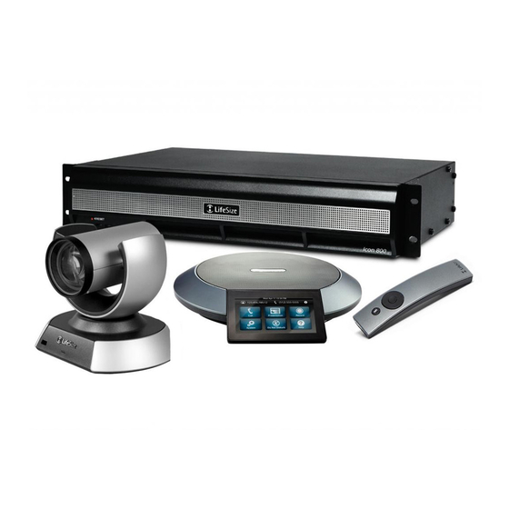
® Lifesize Icon™ Installation Guide May 2014 Lifesize Icon 600 Lifesize Icon 800... -
Page 2: Preparing For Installation
Room Configuration The size, shape, layout, and occupancy of the room dictate where you place your video conferencing components. For example, in a conference room, place a Lifesize Digital MicPod at the center of the group of participants. You can lock the Icon 600 codec with a secure loop to prevent physical removal of the device. For assistance, contact your Lifesize Partner or Lifesize Technical Services. -
Page 3: System Components
The Icon 800 system includes two rack mounting brackets that are located on each side of the front of the chassis. To mount the device in a rack unit, screw these brackets directly to the front of the rack. Two... - Page 4 Removing the Brackets Starting at the right side of the chassis (facing the front with the plastic bezel and Lifesize logo), remove the four flat head screws and the rack mounting bracket from the chassis.
-
Page 5: Installing Your System
To install your Lifesize system, remove all components from the product packaging and place them in the appropriate positions in your conference room or office. - Page 6 Icon 800 only: You can optionally install up to three additional devices in the remaining video ports. Insert the appropriate end of the display cable (HDMI or DVI-I to HDMI) into the port on the back of your display and the opposite end into the port on the back of the codec.
-
Page 7: Configuring Your System
Icon 800: Insert the power cord into the back of the system. Insert the opposite end of the power cord into a grounded power outlet. Apply power using the power switch on the back of the system. Refer to Power and Reboot for Icon 800. -
Page 8: Supported Resolutions
DVI In For use with a second Lifesize camera. If you connect a second camera on Icon 600, you cannot initiate a presentation. For use with devices and laptops for presentations or to share PC data; accepts both digital video and VGA analog signals with the proper adapter cable. -
Page 9: Power And Reboot For Icon 800
Power and Reboot for Icon 800 The power switch on the back of the Icon 800 system controls the main system power. Standby power is available to the system when the AC power cord is plugged in and when the power switch is turned on. - Page 10 Cables The Lifesize video system is shipped with the following cables: • Power cable – Your Lifesize video system ships with a 2-meter power cable. Use an extension cord for longer runs. Icon 600 also includes a PSU. • Ethernet or LAN cable – The video system ships with a 3-meter RJ45 Ethernet/LAN cable. You can substitute a longer Ethernet cable up to 300 feet (cat5e or cat6).
-
Page 11: Troubleshooting
Your system is then configured with the IP address of 169.254.x.x. From a web browser, enter 169.254.1.1 and log in with administrator credentials. The default username and password are admin. Refer to the Lifesize Icon Video System Guide and the browser-based online help to complete the configuration. -
Page 12: Copyright Notice
©2014 Logitech, and its licensors. All rights reserved. Lifesize Communications, a division of Logitech, has made every effort to ensure that the information contained in this document is accurate and reliable, but assumes no responsibility for errors or omissions. Information in this document is subject to change without notice.


Need help?
Do you have a question about the Icon 800 and is the answer not in the manual?
Questions and answers