Table of Contents
Advertisement
Quick Links
Advertisement
Table of Contents

Related Manuals for CTC Union MSW-4424C


Summary of Contents for CTC Union MSW-4424C
- Page 1 MSW-4424C MSW-4424CS L2+ Gigabit Carrier Ethernet Switch...
- Page 2 CTC Union Technologies makes no warranty, representation, or guarantee regarding the suitability of its products for any particular purpose, nor does CTC Union assume any liability arising out of the application or use of any product and specifically disclaims any and all liability, including without limitation any consequential or incidental damages.
- Page 3 MSW-4424C MSW-4424CS This document is the current official release manual. Please check CTC Union's website for any updated manual or contact us by E-mail at sales@ctcu.com. Please address any comments for improving this manual or to point out omissions or errors to marketing@ctcu.com. Thank you.
-
Page 4: Table Of Contents
TABLE OF CONTENTS CHAPTER 1. INTRODUCTION ..................... 18 1.1 P ........................18 RODUCT ESCRIPTION 1.2 P ............................18 ANELS CHAPTER 2. INSTALLATION ....................... 20 2.1 F ........................20 IBER ONNECTIONS 2.2 MGMT P ....................... 20 ONNECTION 2.3 C ......................20 ONSOLE ONNECTION 2.3.1 RJ-45 Pin Assignment ............................ - Page 5 TABLE OF CONTENTS 3.8.14 # clear ip igmp snooping ..........................34 3.8.15 # clear ip statistics ............................34 3.8.16 # clear ipv6 mld snooping ..........................34 3.8.17 # clear ipv6 neighbors ............................ 34 3.8.18 # clear ipv6 statistics ............................34 3.8.19 # clear lacp statistics ............................
- Page 6 TABLE OF CONTENTS 3.9.6.1 (config)# clock summer-time <word16> date ......................49 3.9.6.2 (config)# clock summer-time <word16> recurring .......................50 3.9.6.3 (config)# clock timezone ...............................50 3.9.7 (config)# default access-list rate-limiter ......................51 3.9.8 (config)# dot1x ..............................51 3.9.8.1 (config)# dot1x system-auth-control ..........................51 3.9.8.2 (config)# dot1x re-authentication ..........................52 3.9.8.3 (config)# dot1x authentication timer re-authenticate ....................52 3.9.8.4 (config)# dot1x timeout tx-period ..........................52 3.9.8.5 (config)#dot1x authentication timer inactivity ......................53...
- Page 7 TABLE OF CONTENTS 3.9.18.4 (config-if)# gvrp ................................70 3.9.19 (config)# hostname ............................70 3.9.20 (config)# interface ............................71 3.9.20.1(config)# interface ( <port_type> [ <plist> ] ) ......................71 3.9.20.2 (config)# interface vlan ...............................72 3.9.21 (config)# ip ..............................72 3.9.21.1 (config)# ip arp inspection ............................72 3.9.21.2 (config)# ip arp inspection entry interface .........................72 3.9.21.3 (config)# ip arp inspection translate ...........................73 3.9.21.4 (config)# ip arp inspection vlan ..........................73...
- Page 8 TABLE OF CONTENTS 3.9.21.53 (config-if-vlan)# ip address ............................88 3.9.21.54 (config-if-vlan)# ip dhcp server ..........................89 3.9.21.55 (config-if-vlan)# ip igmp snooping ..........................89 3.9.21.56 (config-if-vlan)# ip igmp snooping compatibility ......................89 3.9.21.57 (config-if-vlan)# ip igmp snooping last-member-query-interval ................90 3.9.21.58 (config-if-vlan)# ip igmp snooping priority .......................90 3.9.21.59 (config-if-vlan)# ip igmp snooping querier .......................90 3.9.21.60 (config-if-vlan)# ip igmp snooping query-interval ....................90 3.9.21.61 (config-if-vlan)# ip igmp snooping query-max-response-time .................91...
- Page 9 TABLE OF CONTENTS 3.9.25.11 (config-line)# location .............................107 3.9.25.12 (config-line)# motd-banner ............................107 3.9.25.13 (config-line)# privilege level ...........................108 3.9.25.14 (config-line)# width ..............................108 3.9.26 (config)# lldp ..............................109 3.9.26.1 (config)# lldp holdtime .............................109 3.9.26.2 (config)# lldp reinit ..............................109 3.9.26.3 (config)# lldp timer ..............................109 3.9.26.4 (config)# lldp transmission-delay ..........................110 3.9.26.5 (config)# lldp med datum ............................110 3.9.26.6 (config)# lldp med fast ..............................111...
- Page 10 TABLE OF CONTENTS 3.9.32.18 (config)# mep <inst> peer-mep-id ..........................130 3.9.32.19 (config)# mep <inst> performance-monitoring ......................130 3.9.32.20 (config)# mep <inst> tst ............................130 3.9.32.21 (config)# mep <inst> tst rx ............................131 3.9.32.22 (config)# mep <inst> tst tx ............................131 3.9.32.23 (config)# mep <inst> vid ............................131 3.9.32.24 (config)# mep <inst>...
- Page 11 TABLE OF CONTENTS 3.9.39.16 (config-if)# qos egress wrr ............................155 3.9.39.17 (config-if)# qos ingress cos .............................156 3.9.39.18 (config-if)# qos ingress dei ............................156 3.9.39.19 (config-if)# qos ingress dpl .............................156 3.9.39.20 (config-if)# qos ingress map tag-cos ........................157 3.9.39.21 (config-if)# qos ingress pcp .............................157 3.9.39.22 (config-if)# qos policer ............................157 3.9.39.23 (config-if)# qos ingress queue-policer ........................158 3.9.39.24 (config-if)# qos ingress shaper ..........................158...
- Page 12 TABLE OF CONTENTS 3.9.45.10 (config-stp-aggr)# spanning-tree restricted-tcn .....................177 3.9.45.11 (config)# spanning-tree edge bpdu-filter .......................177 3.9.45.12 (config)# spanning-tree edge bpdu-guard ......................178 3.9.45.13 (config)# spanning-tree mode ..........................178 3.9.45.14 (config)# spanning-tree mst <instance> priority <prio> ..................178 3.9.45.15 (config)# spanning-tree mst <instance> vlan <v_vlan_list> ..................179 3.9.45.16 (config)# spanning-tree mst forward-time ......................179 3.9.45.17 (config)# spanning-tree mst max-age ........................180 3.9.45.18 (config)# spanning-tree mst max-hops ........................180...
- Page 13 TABLE OF CONTENTS 3.9.51.2 (config)# vlan ethertype s-custom-port ........................197 3.9.51.3 (config)# vlan protocol .............................197 3.9.52 (config)# voice vlan ............................198 3.9.52.1 (config)# voice vlan ..............................198 3.9.52.2 (config)# voice vlan aging-time ..........................199 3.9.52.3 (config)# voice vlan class ............................199 3.9.52.4 (config)# voice vlan oui <oui> [ description <description> ] ..................199 3.9.52.5 (config)# voice vlan vid .............................200 3.9.53 (config)# web privilege group ........................
- Page 14 TABLE OF CONTENTS 4.3.4.2.3.1 Ports ................................235 4.3.4.2.3.2 Rate Limiters ..............................236 4.3.4.2.3.3 Access Control List ............................237 4.3.4.2.4 IP Source Guard ..............................241 4.3.4.2.4.1 Configuration ...............................241 4.3.4.2.4.2 Static Table ..............................242 4.3.4.2.5 ARP inspection ..............................243 4.3.4.2.5.1 Port Configuration ............................243 4.3.4.2.5.2 VLAN Configuration .............................244 4.3.4.2.5.3 Static Table ..............................244 4.3.4.2.5.4 Dynamic Table Configuration ........................245 4.3.4.3 AAA .....................................245 4.3.4.3.1 RADIUS Configuration ............................245...
- Page 15 TABLE OF CONTENTS 4.3.22 VCL ................................295 4.3.22.1 MAC-based VLAN ..............................295 4.3.22.2 Protocol-based VLAN ..............................296 4.3.22.2.1 Protocol to Group .............................296 4.3.22.2.2 Group to VLAN ..............................297 4.3.22.3 IP Subnet-based VLAN ..............................298 4.3.23 Voice VLAN ..............................298 4.3.23.1 Configuration ................................299 4.3.23.2 OUI ...................................300 4.3.24 Ethernet Services ............................
- Page 16 TABLE OF CONTENTS 4.4.4.1.3 Declined IP ................................343 4.4.4.2 Snooping Table ................................343 4.4.4.2.1 Relay Statistics ..............................344 4.4.4.2.2 Detailed Statistics ..............................345 4.4.5 Security ................................346 4.4.5.1 Access Management Statistics ...........................346 4.4.5.2 Network ..................................347 4.4.5.2.1 Port Security ................................347 4.4.5.2.1.1 Switch ................................347 4.4.5.2.1.2 Port Status ..............................348 4.4.5.2.2 NAS ..................................349 4.4.5.2.2.1 Switch ................................349 4.4.5.2.2.2 Port ................................349...
- Page 17 TABLE OF CONTENTS 4.4.15.2 Ports ..................................374 4.5 D ..........................375 IAGNOSTICS 4.5.1 Ping ................................375 4.5.2 Link OAM ............................... 375 4.5.2.1 MIB Retrieval ................................375 4.5.3 Ping6 ................................375 4.6 M ..........................376 AINTENANCE 4.6.1 Restart Device ..............................376 4.6.2 Factory Defaults ............................. 377 4.6.3 Software .................................
-
Page 18: Chapter 1. Introduction
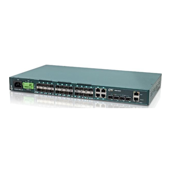
INTRODUCTION CHAPTER 1. INTRODUCTION Thank you for purchasing this product from CTC Union. We hope this product is everything you wanted and more. Our Product Managers and R&D team have placed a "quality first" motto in our development of this series of Ethernet switches with the desire of providing a highly stable and reliable product that will give years of trouble-free operation. - Page 19 AC, DC, 2 AC, 2 DC, AC+DC) Port21~24 Port1~20 Port 25~28 MGMT 1PPS/TOD Combo 1/10G SFP+ 100/1000M SFP Port for SyncE Console Default Push Earth Ground LED Indicators Figure 2. Front Panel for MSW-4424CS Port Button Fan Module Figure 3. Rear Panel for MSW-4424C &MSW-4424CS...
-
Page 20: Chapter 2. Installation
INSTALLATION CHAPTER 2. INSTALLATION The MSW-4424C(S) are designed to be placed on the flat desktop or to be mounted in a standardized 19-inch rack for rack-mount placement. The switch you purchase should come with rack-mounting brackets from the factory and these brackets are used for rack-mounting installation. -
Page 21: Pin Assignment
Transmit Data In from DTE Signal Ground CONSOLE 2.3.2 Accessory Cable This DB9F to RJ-45 cable provides a connection for the RS-232. This cable is used between the MSW-4424C(S) and the serial port of terminal. to PC COM Port Pins RJ-45 Ref. -
Page 22: Rack Mounting
CHAPTER 2 INSTALLATION 2.5 Rack Mounting When installing the rack mount brackets, be sure to correctly align the orientation pin. Use the screws provided in the rack-mounting kit to securely fasten the brackets. Figure 8. Attaching Rack-Mounting Brackets Figure 9. The Switch with Rack-Mounting Brackets Figure 10. -
Page 23: Led Indicators & Reset To Default Button
CHAPTER 2 INSTALLATION 2.6 LED Indicators & Reset to Default Button Color Status Meaning Green The switch is active. Alert The switch does not receive power. Power 1 module is working. PWR 1 Green Power 1 module is off. Power 2 module is working. PWR 2 Green Power 2 module is off. -
Page 24: Chapter 3. Introduction To Cli
PC can be physically connected to the local MSW-4424C(S) Series switch at the CONSOLE port using RJ45 to RS-232 console cable. Accessing the switch via CONSOLE port allows the user to use CLI (Command Line Interface) to manage and configure the device. The out-of- band management is relatively useful when you lose the network connection to the device. -
Page 25: Cli Modes
CHAPTER 3 INTRODUCTION TO CLI 3.3 CLI Modes The Command Line Interface (CLI) is mainly divided into four basic modes; these are User mode, EXEC mode, Config mode and Config Interface mode. After entering the username and password, you start from the EXEC mode (prompted with “#”). -
Page 26: Basic Configurations
CHAPTER 3 INTRODUCTION TO CLI separate them. 2. The uter curly bracket means that this is a must parameter. At leaset one value should be specified. | (Vertical Use a vertical bar to separate { { <address> <netmask> } | Enter IP address or use bar) options. -
Page 27: Save Configurations
CHAPTER 3 INTRODUCTION TO CLI 3.6.3 Save Configurations # copy running-config startup-config Building configuration... % Saving 1469 bytes to flash:startup-config 3.6.4 Restart the Device # reload cold % Cold reload in progress, please stand by. Copyright (C) 2000, 2001, 2002, 2003, 2004, 2005, 2006, 2007, 2008, 2009 Free Software Foundation, Inc. -
Page 28: Show Running Configurations
CHAPTER 3 INTRODUCTION TO CLI ------------------ Image managed Version Date : 2015-01-01T00:03:06+00:00 Alternative Image ------------------ Image : managed.bk Version Date : 2015-08-03T16:21:44+08:00 ------------------ SID : 1 ------------------ Software Version : V1.038 Build Date : 2015-08-03T16:33:15+08:00 3.6.7 Show Running Configurations # show running-config Building configuration... -
Page 29: Help
CHAPTER 3 INTRODUCTION TO CLI interface GigabitEthernet 1/1-5 exit interface GigabitEthernet 1/1-3,5,7 flowcontrol on exit show interface * status disable show clock detail show dot1x show history 3.6.9 Help Help command can be issued in User, Exec, and Global Config mode to get a hint message describing how to use “show”... -
Page 30: Clear Ip Arp
CHAPTER 3 INTRODUCTION TO CLI In User mode, only limited commands are available. These commands are used for clearing statistics, entering Exec mode and pinging the specified destination. To configure a function, you should enter Config mode or Config Interface mode. 3.7.1 >... -
Page 31: Logout
CHAPTER 3 INTRODUCTION TO CLI Explanation: Provide help messages. 3.7.7 > logout Syntax: > logout Explanation: Logout the Command Line Interface. 3.7.8 > ping ip Syntax: > ping ip <v_ip_addr> [ repeat <count> ] [ size <size> ] [ interval <seconds> ] <v_ip_addr>: Specify IPv4 address that you want to ping. -
Page 32: Commands In Exec Mode
CHAPTER 3 INTRODUCTION TO CLI 3.8 Commands in EXEC Mode 3.8.1 # clear access management statistics Syntax: # clear access management statistics Explanation: Clear access (HTTP, HTTPs, SNMP, Telnet, SSH) management statistics. 3.8.2 # clear access-list ace statistics Syntax: # clear access-list ace statistics Explanation: Clear access list entry statistics. -
Page 33: Clear Ip Arp
CHAPTER 3 INTRODUCTION TO CLI Parameter: { [ <evc_id> | all ] }: Clear all or the specified EVC ID's EVC statistics. [ ece [ <ece_id> ] ]: Clear the specified ECE ID's EVC statistics. [ interface ( <port_type> [ <port_list> ] ) ]: Clear the specified interface's EVC statistics. Explanation: Clear Ethernet Virtual Connections statistics. -
Page 34: Clear Ip Dhcp Server Statistics
CHAPTER 3 INTRODUCTION TO CLI 3.8.12 # clear ip dhcp server statistics Syntax: # clear ip dhcp server statistics Explanation: Clear IP DHCP server binding statisctics. 3.8.13 # clear ip dhcp snooping statistics Syntax: # clear ip dhcp snooping statistics [ interface ( <port_type> [ <in_port_list> ] ) ] Explanation: Clear IP DHCP Snooping statistics. -
Page 35: Clear Lacp Statistics
CHAPTER 3 INTRODUCTION TO CLI 3.8.19 # clear lacp statistics Syntax: # clear lacp statistics Explanation: Clear LACP statistics. 3.8.20 # clear lldp statistics Syntax: # clear lldp statistics Explanation: Clear LLDP statistics. 3.8.21 # clear logging Syntax: # clear logging [ info ] [ warning ] [ error ] [ switch <switch_list> ] Explanation: Clear specific syslog events. -
Page 36: Clear Statistics
CHAPTER 3 INTRODUCTION TO CLI 3.8.26 # clear statistics Syntax: # clear statistics [ interface ] ( <port_type> [ <v_port_type_list> ] ) Explanation: Clear Fast Ethernet and/or Gigabit Ethernet interfaces’ statistics. 3.8.27 # config terminal Syntax: # config terminal Explanation: Enter the Global Config mode. Example: # config t (config)#... -
Page 37: Delete
CHAPTER 3 INTRODUCTION TO CLI 3.8.29 # delete Syntax: # delete <path> Explanation: Delete a file saved in Flash. Parameters: <Path : word>: Name of the file in Flash to be deleted. Example: Delete a file named 201 in Flash. # dir Directory of flash: r- 1970-01-01 00:00:00... -
Page 38: Disable & # Enable
CHAPTER 3 INTRODUCTION TO CLI 3.8.31 # disable & # enable Explanation: Return to user mode or enter exec mode. # disable > > > enable # enable 0 > 3.8.32 # dot1x Syntax: # dot1x initialize [ interface ( <port_type> [ <plist> ] ) [ interface ( <port_type>... -
Page 39: Firmware Upgrade
CHAPTER 3 INTRODUCTION TO CLI 3.8.35 # firmware upgrade Syntax: # firmware upgrade <TFTPServer_path_file : word> <TFTPServer_path_file : word>: Specify the TFTP server IP address and firmware filename. Explanation: Upgrade the firmware image. 3.8.36 # ip dhcp retry interface vlan Syntax: # ip dhcp retry interface vlan <vlan_id>... -
Page 40: Reload Cold
CHAPTER 3 INTRODUCTION TO CLI [ size <size> ]: The size or length of echo packets. [ interval <seconds> ]: The time interval between each ping request. [ interface vlan <v_vlan_id> ]: Specify the VLAN ID. 3.8.40 # reload cold Syntax: # reload cold Explanation: Perform a cold reload on the system. -
Page 41: Terminal Exec-Timeout
CHAPTER 3 INTRODUCTION TO CLI Negation: # no terminal editing 3.8.44 # terminal exec-timeout Syntax: # terminal exec-timeout <0-1440> [<0-3600>] Parameters: <0-1440>: Specify the timeout value in minutes. [<0-3600>]: Specify the timeout value in seconds. Explanation: Set up terminal timeout value. Show: >... -
Page 42: Terminal Width
CHAPTER 3 INTRODUCTION TO CLI 3.8.47 # terminal width Syntax: # terminal width <0 or 40-512> Parameters: <0 or 40-512>: Specify the width displayed on the screen. “0” means unlimited width. Explanation: Set up terminal display width. Show: > show terminal # show terminal Negation: # no terminal width 3.8.48 # no port-security shutdown... -
Page 43: Config)# Access Management
CHAPTER 3 INTRODUCTION TO CLI tacacs: Use remote TACACS+ server(s) for authentication. NOTE: Methods that involve remote servers will time out if the remote servers are offline. In this case the next method is tried. Each method is tried and continues until a method either approves or rejects a user. If a remote server is used for primary authentication it is recommended to configure secondary authentication as 'local'. -
Page 44: Config)# Access-List
CHAPTER 3 INTRODUCTION TO CLI 3.9.3 (config)# access-list 3.9.3.1 (config)# access-list ace Syntax: (config)# access-list ace <AceId : 1-256> [ action {deny | filter | permit}] [ dmac-type {any| broadcast | multicast | unicast } ] [frame-type {any| arp|etype|ipv4|ipv4-icmp|ipv4-tcp|ipv4-udp|ipv6|ipv6-icmp|ipv6-tcp|ipv6- udp} ] [ingress {any | interface <PORT_TYPE> }] [logging] [next { <AceId : 1-256>|last}] [policy <PolicyId : 0-255>] [rate- limiter {<RateLimiterId : 1-16>|disable}] [redirect {disable| interface <PORT_TYPE>}] [shutdown] [tag {any|tagged|untagged}] [tag-priority {0-1| 0-3| 2-3| 4-5| 4-7| 6-7| <TagPriority : 0-7>|any}] [vid { <Vid : 1- 4095>|any}]... -
Page 45: Config)# Access-List Ace Update
CHAPTER 3 INTRODUCTION TO CLI 3.9.3.2 (config)# access-list ace update Syntax: (config)# access-list ace update <AceId : 1-256> [ action {deny | filter | permit}] [ dmac-type {any| broadcast | multicast | unicast } ] [frame-type {any| arp|etype|ipv4|ipv4-icmp|ipv4-tcp|ipv4-udp|ipv6|ipv6-icmp|ipv6-tcp|ipv6- udp} ] [ingress {any | interface <PORT_TYPE> }] [logging] [next { <AceId : 1-256>|last}] [policy <PolicyId : 0-255>] [rate- limiter {<RateLimiterId : 1-16>|disable}] [redirect {disable| interface <PORT_TYPE>}] [shutdown] [tag {any|tagged|untagged}] [tag-priority {0-1| 0-3| 2-3| 4-5| 4-7| 6-7| <TagPriority : 0-7>|any}] [vid { <Vid : 1- 4095>|any}]... -
Page 46: Config)# Access-List Rate-Limiter
CHAPTER 3 INTRODUCTION TO CLI 3.9.3.3 (config)# access-list rate-limiter Syntax: (config)# access-list rate-limiter [ <rate_limiter_list> ] { pps <pps_rate> | 100pps <pps100_rate> | kpps <kpps_rate> | 100kbps <kpbs100_rate> } Explanation: Configure rate limiter that applies to each rate limit ID. Parameters: [ <rate_limiter_list>... -
Page 47: Config-If)# Access-List Port-State
CHAPTER 3 INTRODUCTION TO CLI Negation: (config-if)# no access-list policy 3.9.3.7 (config-if)# access-list port-state Syntax: (config-if)# access-list port-state Explanation: Enable a specific port’s port state. Negation: (config-if)# no access-list port-state 3.9.3.8 (config-if)# access-list rate-limiter Syntax: (config-if)# access-list rate-limiter <rate_limiter_id> Parameters: <rate_limiter_id:1-16>: Specify a rate limiter ID to a specific port. -
Page 48: Config)# Aggregation
CHAPTER 3 INTRODUCTION TO CLI 3.9.4 (config)# aggregation 3.9.4.1 (config)# aggregation mode Syntax: (config)# aggregation mode { [ smac ] [ dmac ] [ ip ] [ port ] } Explanation: Configure aggregation mode. Parameters: [smac]: All traffic from the same Source MAC address is output on the same link in a trunk. [dmac]: All traffic with the same Destination MAC address is output on the same link in a trunk. -
Page 49: Config)# Banner Exec
CHAPTER 3 INTRODUCTION TO CLI 3.9.5.2 (config)# banner exec <banner> Syntax: (config)# banner exec <banner> Explanation: Display the configured message when successfully entering Exec mode. Negation: (config)# no banner exec 3.9.5.3 (config)# banner login <banner> Syntax: (config)# banner login <banner> Explanation: Display the configured message when prompted for login ID and password. -
Page 50: Config)# Clock Summer-Time
CHAPTER 3 INTRODUCTION TO CLI Negation: (config)# no clock summer-time Show: > show clock > show clock detail # show clock # show clock detail 3.9.6.2 (config)# clock summer-time <word16> recurring Syntax: (config)# clock summer-time <word16> recurring [ <start_week_var> <start_day_var> <start_month_var> <start_hour_var>...Recurring -
Page 51: (Config)# Default Access-List Rate-Limiter 1
CHAPTER 3 INTRODUCTION TO CLI <word16>: Specify the name of the timezone. <-23-23>: Hours offset from UTC. [<0-59>]: Minutes offset from UTC. Negation: (config)# no clock timezone Show: # show clock # show clock detail 3.9.7 (config)# default access-list rate-limiter Syntax: (config)# default access-list rate-limiter [ <rate_limiter_list>... -
Page 52: Config)# Dot1X Re-Authentication
CHAPTER 3 INTRODUCTION TO CLI 3.9.8.2 (config)# dot1x re-authentication Syntax: (config)# dot1x re-authentication Explanation: Set clients to be re-authenticated after an interval set in "Re-authenticate" field. Re-autentication can be used to detect if a new device is attached to a switch port. Example: Enable re-authentication function. -
Page 53: Config)#Dot1X Authentication Timer Inactivity
CHAPTER 3 INTRODUCTION TO CLI # config t (config)# dot1x timeout tx-period 30 Negation: (config)# no dot1x timeout tx-period 3.9.8.5 (config)#dot1x authentication timer inactivity Syntax: (config)# dot1x authentication timer inactivity <10-1000000> Explanation: Specify the period that is used to age out a client’s allowed access to the switch via 802.1X and MAC- based authentication. -
Page 54: Config)# Dot1X Guest-Vlan
CHAPTER 3 INTRODUCTION TO CLI Parameters: { [ guest-vlan ] [ radius-qos ] [ radius-vlan ] }: [guest-vlan]: Enable guest VLAN. A Guest VLAN is a special VLAN typically with limited network access. When checked, the individual ports' ditto setting determines whether the port can be moved into Guest VLAN. -
Page 55: Config-If)# Dot1X Port-Control
CHAPTER 3 INTRODUCTION TO CLI Explanation: The maximum number of times the switch transmits an EAPOL Request Identity frame without receiving a response before adding a port to the Guest VLAN. The value can only be changed when the Guest VLAN option is globally enabled. -
Page 56: Config-If)# Dot1X Guest-Vlan
CHAPTER 3 INTRODUCTION TO CLI Negation: (config-if)# no dot1x port-control 3.9.8.12 (config-if)# dot1x guest-vlan Syntax: (config-if)# dot1x guest-vlan Explanation: Enable the guest VLAN on the selected interfaces. Parameters: None. Example: Enable guest VLAN on port 1-10. # config t (config)# interface gigabitethernet 1/1-10 (config-if)# dot1x guest-vlan Negation: (config-if)# no dot1x guest-vlan 3.9.8.13 (config-if)# dot1x radius-qos... -
Page 57: Config-If)# Dot1X Re-Authenticate
CHAPTER 3 INTRODUCTION TO CLI Negation: (config-if)# no dot1x radius-vlan 3.9.8.15 (config-if)# dot1x re-authenticate Syntax: (config-if)# dot1x re-authenticate Explanation: Schedules reauthentication to whenever the quiet-period of the port runs out (EAPOL-based authentication). For MAC-based authentication, reauthentication will be attempted immediately. This command only has effect for successfully authenticated clients on the port and will not cause the clients to get temporarily unauthorized. -
Page 58: Config)# Enable Secret
CHAPTER 3 INTRODUCTION TO CLI Syntax: (config)# enable password [level <priv: 1-15>] <password> Explanation: Configure enable password and privilege level. Parameters: [level <priv: 1-15>]: Specify the privilege level for this password. <password>: Specify a password for Enable mode. Negation: (config)# no enable password [ level <priv> ] 3.9.10.3 (config)# enable secret Syntax: (config)# enable secret { 0 | 5 } [ level <priv: 1-15>... -
Page 59: Config)# Eps
CHAPTER 3 INTRODUCTION TO CLI Parameters: <inst>: Specify the instance number. { lockout | forced | manualp | manualw | exercise | freeze | lockoutlocal }: Specify one of the EPS commands required for EPS configuration. lockout: End-to-end lock out of the protection entity. forced: Forced switch to the protection entity.Domain -
Page 60: Config)# Eps
CHAPTER 3 INTRODUCTION TO CLI <inst>: Specify the instance number. holdoff <hold>: Specify the hold off timer. The allowed value is in 100 ms (Max 10 sec.). Negation: (config)# no eps <inst> holdoff Show: # show eps [ <inst> ] [ detail ] 3.9.11.5 (config)# eps <inst>...Mep-Work Mep-Protect Mep-Aps -
Page 61: Config)# Erps
CHAPTER 3 INTRODUCTION TO CLI <guard_time_ms: 10-2000>: Specify the guard time. The allowed range is 10 to 2000 ms. Negation: (config)# no erps <group> guard Show: # show erps [ <groups> ] [ detail | statistics ] 3.9.12.2 (config)# erps <group> holdoff <holdoff_time_ms> Syntax: (config)# erps <group>...Holdoff -
Page 62: Config)# Erps
CHAPTER 3 INTRODUCTION TO CLI 3.9.12.4 (config)# erps <group> mep port0 sf <p0_sf> aps <p0_aps> port1 sf <p1_sf> aps <p1_aps> Syntax: (config)# erps <group> mep port0 sf <p0_sf> aps <p0_aps> port1 sf <p1_sf> aps <p1_aps> Explanation: Configure the specified group’s MEP & APS settings. Parameters: <group: 1-64>: Specify a group number.Mep Port0 Sf Aps Port1 Sf Aps -
Page 63: Config)# Erps
CHAPTER 3 INTRODUCTION TO CLI { owner | neighbor }: Specify the ring port is a owner or neighbor. RPL (Ring Protection Link) is responsible for blocking traffic over the RPL so that no loops are formed in the Ethernet traffic. { port0 | port1 }: Specify the port applies to this rule.Sub Port0 Interface { { Port1 Interface } | { Interconnect [ Virtual-Channel ] -
Page 64: Config)# Erps
CHAPTER 3 INTRODUCTION TO CLI 3.9.12.9 (config)# erps <group> version { 1 | 2 } Syntax: (config)# erps <group> version { 1 | 2 } Explanation: Configure ERPS version for a specific profile. Parameters: <group: 1-64>: Specify a group number. The allowed range is from 1 to 64. { 1 | 2 }: Specify ERPS version 1 or 2.Version { 1 | 2 -
Page 65: Evc Ece
CHAPTER 3 INTRODUCTION TO CLI { [ vid <evc_vid> ] }: Specify the VLAN ID in the PB network. It may be inserted in a C-tag, S-tag or S-custom tag depending on the NNI port VLAN configuration. The allowed range is from 1 through 4095. [ ivid <ivid>... -
Page 66: Evc Policer
CHAPTER 3 INTRODUCTION TO CLI untagged: The ECE will match untagged frames only. tagged: The ECE will match tagged frames only. c-tagged: The ECE will match custom tagged frames only. s-tagged: The ECE will match service tagged frames only. any: The ECE will match both tagged and untagged frames. [ frame-type { any | ipv4 | ipv6 } ]: The frame type for the ECE. - Page 67 CHAPTER 3 INTRODUCTION TO CLI Explanation: Configure a EVCE policer entry. Parameters: [ update ]: Update this policer entey. <policer_id>: Specify the Policer ID that is used to identify one of the 2048 policers. [ { enable | disable } ]: The administrative state of the bandwidth profile. The allowed values are: enable: The bandwidth profile enabled.
-
Page 68: Config-If)# Excessive-Restart
CHAPTER 3 INTRODUCTION TO CLI 3.9.14 (config-if)# excessive-restart Syntax: (config-if)# excessive-restart Explanation: Restart backoff algorithm after 16 collisions (No excessive-restart means discard frames after 16 collisions.) Negation: (config-if)# no excessive-restart Show: > show interface ( <port_type> [ <v_port_type_list> ] ) status # show interface ( <port_type>... -
Page 69: Config)# Fanmode { Auto | Full | Low
CHAPTER 3 INTRODUCTION TO CLI 3.9.17 (config)# fanmode { auto | full | low } Syntax: (config)# fanmode { auto | full | low } Explanation: Adjust the fan speed of the device. Parameters: auto: The fan speed is adjusted automatically depending on the current temperature of the device. full: The fan operates in full speed. -
Page 70: Config)# Gvrp Time
CHAPTER 3 INTRODUCTION TO CLI 3.9.18.3 (config)# gvrp time Syntax: (config)# gvrp time { [ join-time <jointime> ] [ leave-time <leavetime> ] [ leave-all-time <leavealltime> ] } Explanation: Set up the maximum number of VLANs can be learned via GVRP. Parameters: [ join-time <jointime>... -
Page 71: Config)# Interface
CHAPTER 3 INTRODUCTION TO CLI <WORD32>: Specify a descriptive name for this device. Indicate the hostname for this device. Alphabets (A-Z; a-z), digits (0-9) and minus sign (-) can be used. However, space characters are not allowed. The first character must be an alphabet character. -
Page 72: Config)# Interface Vlan
CHAPTER 3 INTRODUCTION TO CLI 3.9.20.2 (config)# interface vlan Syntax: (config)# interface vlan <vlist> Explanation: Enter Config Interface VLAN mode for this specific interface. Example: Enter Config Interface VLAN 1 for port 1. # config t (config)# (config)# interface vlan 1 (config-if-vlan)# 3.9.21 (config)# ip 3.9.21.1 (config)# ip arp inspection... -
Page 73: Config)# Ip Arp Inspection Translate
CHAPTER 3 INTRODUCTION TO CLI 3.9.21.3 (config)# ip arp inspection translate Syntax: (config)# ip arp inspection translate [ interface <port_type> <in_port_type_id> <vlan_var> <mac_var> <ipv4_var> ] Explanation: Translate the dynamic entry to static one. Parameters: <port_type> <in_port_type_id>: Specify the port type and port number. <vlan_var>: Specify a configured VLAN ID. -
Page 74: Config)# Ip Dhcp Excluded-Address
CHAPTER 3 INTRODUCTION TO CLI Show: < show ip arp # show ip arp Clear: # clear ip arp 3.9.21.6 (config)# ip dhcp excluded-address Syntax: (config)# ip dhcp excluded-address <low_ip> [ <high_ip> ] Parameters: <low_ip> [ <high_ip> ]: Specify the IP address range that will not be used for DHCP IP assignment. Explanation: Configure IP addresses that are not used for DHCP IP allocation. -
Page 75: Config)# Ip Dhcp Relay Information Circuit-Id Format
CHAPTER 3 INTRODUCTION TO CLI Explanation: Enable DHCP relay function. Example: Enable DHCP relay function. # config t (config)# ip dhcp relay Negation: (config)# no ip dhcp relay Show: > show ip dhcp relay [statistics] # show ip dhcp relay [statistics] Clear: # clear ip dhcp relay statistics 3.9.21.9 (config)# ip dhcp relay information circuit-id format Syntax: (config)# ip dhcp relay information circuit-id format { standard | tr101 | alias }... -
Page 76: Config)# Ip Dhcp Relay Information Policy {Drop | Keep |Replace
CHAPTER 3 INTRODUCTION TO CLI 3.9.21.11 (config)# ip dhcp relay information policy {drop | keep |replace} Syntax: (config)# ip dhcp relay information policy { drop | keep | replace } Explanation: Specify DHCP Relay information reforwarding policy action. Parameters: { drop | keep | replace }: Specify one of the relay information policy options. drop: Drop the packet when it receives a DHCP message that already contains relay information. -
Page 77: Config)# Ip Dhcp Server
CHAPTER 3 INTRODUCTION TO CLI Explanation: Specify the remoted ID format inserted in DHCP Relay information option. Negation: (config)# no ip dhcp relay information remote-id format Show: # show ip dhcp relay 3.9.21.14 (config)# ip dhcp server Syntax: (config)# ip dhcp server Explanation: Enable DHCP server function globally. -
Page 78: Config)# Ip Dhcp Snooping Table Interval
CHAPTER 3 INTRODUCTION TO CLI Show: > show ip dhcp snooping [ interface ( <port_type> [ <in_port_list> ] ) ] # show ip dhcp snooping [ interface ( <port_type> [ <in_port_list> ] ) ] # show ip dhcp snooping table 3.9.21.17 (config)# ip dhcp snooping table interval Syntax: (config)# ip dhcp snooping table interval <seconds>... -
Page 79: Config)# Ip Dns Proxy
CHAPTER 3 INTRODUCTION TO CLI Explanation: Configure the allowed VLAN when DHCP Snooping is enabled. Show: > show ip dhcp snooping [ interface ( <port_type> [ <in_port_list> ] ) ] # show ip dhcp snooping [ interface ( <port_type> [ <in_port_list> ] ) ] # show ip dhcp snooping table 3.9.21.21 (config)# ip dns proxy Syntax: (config)# ip dns proxy... -
Page 80: Config)# Ip Http Secure-Redirect
CHAPTER 3 INTRODUCTION TO CLI 3.9.21.24 (config)# ip http secure-redirect Syntax: (config)# ip http secure-redirect Explanation: Enable the HTTPS redirect mode operation. It applies only if HTTPS mode is "Enabled". Automatically redirects HTTP of web browser to an HTTPS connection when both HTTPS mode and Automatic Redirect are enabled. Example: Enable HTTPs automatic redirect mode. -
Page 81: Config)# Ip Igmp Snooping Vlan
CHAPTER 3 INTRODUCTION TO CLI 3.9.21.27 (config)# ip igmp snooping vlan Syntax: (config)# ip igmp snooping vlan <v_vlan_list> Explanation: Enable IGMP function for specific VLANs. Parameters: <v_vlan_list>: Specify valid IGMP VLANs. Negation: (config)# no ip igmp snooping vlan [ <v_vlan_list> ] Show: # show ip igmp snooping Clear: # clear ip igmp snooping [ vlan <v_vlan_list>... -
Page 82: Config)# Ip Route
CHAPTER 3 INTRODUCTION TO CLI dhcp [ interface vlan <v_vlan_id> ]: Configure DNS IP address via specific VLAN DHCP server. Negation: (config)# no ip name-server Show: > show ip name-server # show ip name-server 3.9.21.31 (config)# ip route Syntax: (config)# ip route <v_ipv4_addr> <v_ipv4_netmask> <v_ipv4_gw> Explanation: Configure a static IP route. -
Page 83: Config)# Ip Source Binding Interface
CHAPTER 3 INTRODUCTION TO CLI # show ipv6 route [interface vlan<vlan_list>] # show ip route 127.0.0.1/32 via 127.0.0.1 <UP HOST> 224.0.0.0/4 via 127.0.0.1 <UP> # show ipv6 route interface vlan 1 ::1/128 via ::1 <UP HOST> 3.9.21.33 (config)# ip source binding interface Syntax: (config)# ip source binding interface <port_type>... -
Page 84: Config)# Ip Verify Source Translate
CHAPTER 3 INTRODUCTION TO CLI Syntax: (config)# ip verify source Explanation: Enable IP source guard function. Negation: (config)# no ip verify source Show: > show ip verify source [ interface ( <port_type> [ <in_port_type_list> ] ) ] # show ip verify source [ interface ( <port_type> [ <in_port_type_list> ] ) ] 3.9.21.36 (config)# ip verify source translate Syntax: (config)# ip verify source translate Explanation: Translate Dynamic entries to Static ones. -
Page 85: Config-If)# Ip Arp Inspection Trust
CHAPTER 3 INTRODUCTION TO CLI deny: Log denied entries. permit: Log permitted entries. all: Log all entries. Negation: (config-if)# no ip arp inspection logging 3.9.21.40 (config-if)# ip arp inspection trust Syntax: (config-if)# ip arp inspection trust Explanation: Enable trust state on the selected interfaces. Negation: (config-if)# no ip arp inspection trust 3.9.21.41 (config-if)# ip dhcp snooping trust Syntax: (config-if)# ip dhcp snooping trust... -
Page 86: Config-If)# Ip Dhcp Snooping Limit
CHAPTER 3 INTRODUCTION TO CLI { none | alias | configured }: Specify DHCP Option 82 suboption 6 (subscriber ID). none: Sub-option 6 is not used. alias: Use the individual values for port Alias on a per port basis. configured: Configure the desired Subscriber ID. Show: >... -
Page 87: Config-If)# Ip Igmp Snooping Filter
CHAPTER 3 INTRODUCTION TO CLI 3.9.21.47 (config-if)# ip igmp snooping filter Syntax: (config-if)# ip igmp snooping filter <profile_name> Explanation: Use this command to filter specific multicast traffic on a per port basis. Parameters: <profile_name>: Specify the configured multicast groups that are denied on a port. When a certain multicast group is selected on a port, IGMP join reports received on a port are dropped. -
Page 88: Config-If)# Ip Igmp Snooping Mrouter
CHAPTER 3 INTRODUCTION TO CLI 3.9.21.50 (config-if)# ip igmp snooping mrouter Syntax: (config-if)# ip igmp snooping mrouter Explanation: Set this interface to Router port. If IGMP snooping cannot locate the IGMP querier, you can manually designate a port which is connected to a known IGMP querier (i.e., a multicast router/switch). This interface will then join all the current multicast groups supported by the attached router/switch to ensure that multicast traffic is passed to all appropriate interfaces within the switch. -
Page 89: Config-If-Vlan)# Ip Dhcp Server
CHAPTER 3 INTRODUCTION TO CLI dhcp [ fallback <fallback_address> <fallback_netmask> [ timeout <fallback_timeout> ] ]: Use DHCP server to automatically assign IP address. fallback <fallback_address> <fallback_netmask>: specify Fallback IP address and subnet mask. timeout <fallback_timeout>: Specify Fallback timeout value. Negation: (config-if-vlan)# no ip address Show: >... -
Page 90: Config-If-Vlan)# Ip Igmp Snooping Last-Member-Query-Interval
CHAPTER 3 INTRODUCTION TO CLI v3: Compatible with IGMP version 3. Negation: (config-if-vlan)# no ip igmp snooping compatibility 3.9.21.57 (config-if-vlan)# ip igmp snooping last-member-query-interval Syntax: (config-if-vlan)# ip igmp snooping last-member-query-interval <ipmc_lmqi> Explanation: LMQI stands for Last Member Query Interval and is to configure the maximum time to wait for IGMP/MLD report memberships on a receiver port before removing the port from multicast group membership. -
Page 91: Config-If-Vlan)# Ip Igmp Snooping Query-Max-Response-Time
CHAPTER 3 INTRODUCTION TO CLI Parameters: <ipmc_qi: 1-31744>: Specify IPMC Query interval value. The valid value is 1~31744. Negation: (config-if-vlan)# no ip igmp snooping query-interval 3.9.21.61 (config-if-vlan)# ip igmp snooping query-max-response-time Syntax: (config-if-vlan)# ip igmp snooping query-max-response-time <ipmc_qri> Explanation: Specify IPMC Query Response time value. Parameters: <ipmc_qri>: Specify IPMC Query Response time value. -
Page 92: Config-If-Vlan)# Ipv6 Address
CHAPTER 3 INTRODUCTION TO CLI 3.9.21.64 (config-if-vlan)# ipv6 address Syntax: (config-if-vlan)# ipv6 address <subnet> Explanation: Configure IPv6 address for this VLAN interface. Parameters: <subnet>: Specify IPv6 address in X:X:X:X::X/<0-128> format. Negation: (config-if-vlan)# no ipv6 address [ <ipv6_subnet> ] Show: > show ip interface brief >... -
Page 93: Config-If-Vlan)# Ipv6 Mld Snooping Last-Member-Query-Interval
CHAPTER 3 INTRODUCTION TO CLI 3.9.21.67 (config-if-vlan)# ipv6 mld snooping last-member-query-interval Syntax: (config-if-vlan)# ipv6 mld snooping last-member-query-interval <ipmc_lmqi> Explanation: LMQI stands for Last Member Query Interval and is to configure the maximum time to wait for IGMP/MLD report memberships on a receiver port before removing the port from multicast group membership. The allowed range is 0~31744 tenths of a second. -
Page 94: Config-If-Vlan)# Ipv6 Mld Snooping Query-Max-Response-Time
CHAPTER 3 INTRODUCTION TO CLI 3.9.21.71 (config-if-vlan)# ipv6 mld snooping query-max-response-time <ipmc_qri> Syntax: (config-if-vlan)# ipv6 mld snooping query-max-response-time <ipmc_qri> Explanation: Specify MLD Query Response time value. Parameters: <ipmc_qri>: Specify MLD Query Response time value. The valid value is 1~31744. Negation: (config-if-vlan)# no ipv6 mld snooping query-max-response-time 3.9.21.72 (config-if-vlan)# ipv6 mld snooping robustness-variable <ipmc_rv>... -
Page 95: Config)# Ipmc Profile
CHAPTER 3 INTRODUCTION TO CLI Show: # show ipmc profile 3.9.22.2 (config)# ipmc profile <profile_name> Syntax: (config)# ipmc profile <profile_name> Parameters: <profile_name: word16>: Specify the desired profile name in 16 characters. When entered is pressed, the command will change to (config-ipmc-profile)#. Explanation: Set up an IPMC profile. -
Page 96: Config-Ipmc-Profile)# Description
CHAPTER 3 INTRODUCTION TO CLI Example: To default IPMC Profile Rule (Entry 1) for specific IPMC Profile. # config t (config)# ipmc profile goldpass (config-ipmc-profile)# default range 1 Negation: (config-ipmc-profile)# no range <entry_name> Show: # show ipmc profile #show ipmc profile [ <profile_name> ] [ detail ] 3.9.22.5 (config-ipmc-profile)# description Syntax: (config-ipmc-profile)# description <profile_desc>... -
Page 97: Config)# Ipv6 Mld Host-Proxy
CHAPTER 3 INTRODUCTION TO CLI Negation: (config-ipmc-profile)# no range <entry_name> Show: # show ipmc profile #show ipmc profile [ <profile_name> ] [ detail ] 3.9.23 (config)# ipv6 mld host-proxy 3.9.23.1 (config)# ipv6 mld host-proxy Syntax: (config)# ipv6 mld host-proxy Explanation: Enable IPv6 MLD proxy. When MLD proxy is enabled, the switch exchanges MLD messages with the router on its upstream interface, and performs the host portion of the MLD task on the upstream interface as follows: ... -
Page 98: Config)# Ipv6 Mld Snooping
CHAPTER 3 INTRODUCTION TO CLI # show ipv6 mld snooping [ vlan <v_vlan_list> ] [ group-database [ interface ( <port_type> [ <v_port_type_list> ] ) ] [ sfm-information ] ] [ detail ] 3.9.23.3 (config)# ipv6 mld snooping Syntax: (config)# ipv6 mld snooping Explanation: Enable MLD Snooping feature globally. -
Page 99: Config)# Ipv6 Mld Ssm-Range
CHAPTER 3 INTRODUCTION TO CLI 3.9.23.5 (config)# ipv6 mld ssm-range Syntax: (config)# ipv6 mld ssm-range <v_ipv6_mcast> <ipv6_prefix_length> Parameters: <v_ipv6_mcast>: Specify valid IPv6 mluticast address. <ipv6_prefix_length>: Specify prefix length range from 8 to 128. Explanation: Specify SSM (Source-Specific Multicast) Range. This setting allows the SSM-aware hosts and routers run the SSM service model for the groups in the address range. -
Page 100: Config-If)# Ipv6 Mld Snooping Filter
CHAPTER 3 INTRODUCTION TO CLI <v_ipv6_subnet>: Specify IPv6 route address. { <v_ipv6_ucast> | interface vlan <v_vlan_id> <v_ipv6_addr> }: Specify one of the options. This could be either IPv6 next hop unicast address or an interface. Explanation: Configure a static IPv6 route. Negation: (config)# no ipv6 route <v_ipv6_subnet>... -
Page 101: Config-If)# Ipv6 Mld Snooping Mrouter
CHAPTER 3 INTRODUCTION TO CLI <throttling>: This field limits the maximum number of multicast groups that a port can join at the same time. When the maximum number is reached on a port, any new IGMP join reports will be dropped. By default, unlimited is selected. -
Page 102: Config-If)# Lacp
CHAPTER 3 INTRODUCTION TO CLI 3.9.24.2 (config-if)# lacp Syntax: (config-if)# lacp Explanation: Enable LACP on this interface. Example: Enable LACP on port 1. # config t (config)# interface GigabitEthernet 1/1 (config-if)# lacp (config-if)# Negation: (config-if)# no lacp Show: # show lacp { internal | statistics | system-id | neighbour } Clear: # clear lacp statistics 3.9.24.3 (config-if)# lacp key Syntax: (config-if)# lacp key { <v_1_to_65535>... -
Page 103: Config-If)# Lacp Role { Active | Passive
CHAPTER 3 INTRODUCTION TO CLI 3.9.24.5 (config-if)# lacp role { active | passive } Syntax: (config-if)# lacp role { active | passive } Explanation: Configure LACP role for this interface. Parameters: { active | passive }: Specify either “Active” or “Passive” role depending on the device’s capability of negotiating and sending LACP control packets. -
Page 104: Config-Line)# Do
CHAPTER 3 INTRODUCTION TO CLI Example: Enter Console 0 mode. # config t (config)# line console 0 (config-line)# Show: > show line [ alive ] # show line [ alive ] 3.9.25.2 (config-line)# do Syntax: (config-line)# do <command> Explanation: To run EXEC. commands. Parameters: <command>: Enter the EXEC. -
Page 105: Config-Line)# Exec-Banner
CHAPTER 3 INTRODUCTION TO CLI # config t (config)# line console 0 (config-line)# end 3.9.25.5 (config-line)# exec-banner Syntax: (config-line)# exec-banner Explanation: Enable the display of EXEC banner. Example: Enable the display of EXEC banner. # config t (config)# line console 0 (config-line)# exec-banner Negation: (config-line)# no exec-banner Show: >... -
Page 106: Config-Line)# Help
CHAPTER 3 INTRODUCTION TO CLI # config t (config)# line console 0 (config-line)# exit (config)# 3.9.25.8 (config-line)# help Syntax: (config-line)# help Explanation: Show the Help explanation. Example: Show Help explanation. # config t (config)# line console 0 (config-line)# help Help may be requested at any point in a command by entering a question mark '?'. -
Page 107: Config-Line)# Length
CHAPTER 3 INTRODUCTION TO CLI 3.9.25.10 (config-line)# length Syntax: (config-line)# length <length> Explanation: Configure the number of lines displayed on the screen. Parameters: <length>: Specify the number of lines displayed on the screen. The allowed range is 3 to 512. Specify “0” for no pausing. -
Page 108: (Config-Line)# Privilege Level 5
CHAPTER 3 INTRODUCTION TO CLI Example: Enable motd banner. # config t (config)# line console 0 (config-line)# motd-banner (config-line)# Negation: (config-line)# no motd-banner Show: > show line [ alive ] # show line [ alive ] 3.9.25.13 (config-line)# privilege level Syntax: (config-line)# privilege level <privileged_level>... -
Page 109: Config)# Lldp
CHAPTER 3 INTRODUCTION TO CLI Negation: (config-line)# no width Show: > show line [ alive ] # show line [ alive ] 3.9.26 (config)# lldp 3.9.26.1 (config)# lldp holdtime Syntax: (config)# lldp holdtime <val> Explanation: This setting defines how long LLDP frames are considered valid and is used to compute the TTL. The default is 4. -
Page 110: Config)# Lldp Transmission-Delay
CHAPTER 3 INTRODUCTION TO CLI <val>: Specify a value between 5 and 32768 (seconds). Example: Set the LLDP timer value to 35. # config t (config)# lldp timer 35 Negation: (config)# no lldp timer 3.9.26.4 (config)# lldp transmission-delay Syntax: (config)# lldp transmission-delay <val> Parameters: <val>: Specify a value between 1 and 8192 (seconds). -
Page 111: (Config)# Lldp Med Fast 5
CHAPTER 3 INTRODUCTION TO CLI # config t (config)# lldp med datum wgs84 Negation: (config)# no lldp med datum 3.9.26.6 (config)# lldp med fast Syntax: (config)# lldp med fast <v_1_to_10> Explanation: Rapid startup and Emergency Call Service Location Identification Discovery of endpoints is a critically important aspect of VoIP systems in general. -
Page 112: Config)# Lldp Med Location-Tlv Civic-Addr
CHAPTER 3 INTRODUCTION TO CLI # config t (config)# lldp med location-tlv altitude floors 10 Negation: (config)# no lldp med location-tlv altitude 3.9.26.8 (config)# lldp med location-tlv civic-addr Syntax: (config)# lldp med location-tlv civic-addr { country | state | county | city | district | block | street | leading- street-direction | trailing-street-suffix | street-suffix | house-no | house-no-suffix | landmark | additional-info | name | zip-code | building | apartment | floor | room-number | place-type | postal-community-name | p-o-box | additional-code } <v_string250>... -
Page 113: (Config)# Lldp Med Location-Tlv Elin-Addr 911
CHAPTER 3 INTRODUCTION TO CLI floor: Example: 4. room-number: Room number - Example: 450F. place-type: Example: Office. postal-community-name: Example: Leonia. p-o-box: Example: 12345. additional code: Example: 1320300003. Example: Set the country code to “UK”. Example: Set the holdtime to 5. # config t (config)# lldp med location-tlv civic-addr country UK Negation: (config)# no lldp med location-tlv civic-addr { country | state | county | city | district | block | street |... -
Page 114: Config)# Lldp Med Location-Tlv Longitude
CHAPTER 3 INTRODUCTION TO CLI Example: Set the holdtime to 5. # config t (config)# lldp med location-tlv latitude north 5 Negation: (config)# no lldp med location-tlv latitude 3.9.26.11 (config)# lldp med location-tlv longitude Syntax: (config)# lldp med location-tlv longitude { west | east } <v_word9> Explanation: Configure a value for longitude. -
Page 115: Config-If)# Lldp Cdp-Aware
CHAPTER 3 INTRODUCTION TO CLI # config t (config)# lldp med media-vlan-policy 1 voice tagged 100 l2-priority 7 DSCP 63 Negation: (config)# no lldp med media-vlan-policy <policies_list> Show: > show lldp med media-vlan-policy [ <v_0_to_31> ] # show lldp med media-vlan-policy [ <v_0_to_31> ] 3.9.26.13 (config-if)# lldp cdp-aware Syntax: (config-if)# lldp cdp-aware Explanation: Configures if the interface shall be CDP aware (CDP discovery information is added to the LLDP neighbor... -
Page 116: Config-If)# Lldp Receive
CHAPTER 3 INTRODUCTION TO CLI Show: > show lldp med media-vlan-policy [ <v_0_to_31> ] # show lldp med media-vlan-policy [ <v_0_to_31> ] 3.9.26.16 (config-if)# lldp receive Syntax: (config-if)# lldp receive Explanation: The switch will analyze LLDP information received from neighbours. Negation: (config-if)# no lldp receive Show: >... -
Page 117: (Config)# Logging Host 192.168.1.253
CHAPTER 3 INTRODUCTION TO CLI received on UDP port 514. Syslog server will not send acknowledgments back to the sender since UDP is a connectionless protocol and it does not provide acknowledgments. The syslog packet will always send out, even if the syslog server does not exist. -
Page 118: Config)# Loop-Protect
CHAPTER 3 INTRODUCTION TO CLI Example: Send error messages to log server. # config t (config)# logging level error Show: # show logging # show logging <logging_id: 1-4294967295> # show logging [info] [warning] [error] 3.9.28 (config)# loop-protect 3.9.28.1 (config)# loop-protect Syntax: (config)# loop-protect Explanation: Enable loop protection function. -
Page 119: Config)# Loop-Protect Transmit-Time
CHAPTER 3 INTRODUCTION TO CLI 3.9.28.3 (config)# loop-protect transmit-time Syntax: (config)# loop-protect transmit-time <t> Explanation: Configure the interval between each loop protection PDU sent on each port. Parameters: <t: 1-10>: Specify a transmit time value. The valid values are from 1 to 10 seconds. Example: Set the transmit time value to 5 seconds. -
Page 120: Config)# Mac
CHAPTER 3 INTRODUCTION TO CLI Show: # show loop-protect [ interface ( <port_type> [ <plist> ] ) ] 3.9.29 (config)# mac 3.9.29.1 (config)# mac address-table aging-time Syntax: (config)# mac address-table aging-time <v_0_10_to_1000000> Explanation: Configure the aging time for a learned MAC to be appeared in MAC learning table. Parameters: <v_0_10_to_1000000>: Specify an aging time value for MAC address table. -
Page 121: Config-If)# Mac Address-Table Learning
CHAPTER 3 INTRODUCTION TO CLI Negation: (config)# no mac address-table static <v_mac_addr> vlan <v_vlan_id> interface ( <port_type> [ <v_port_type_list> ] ) Show: > show mac address-table [ conf | static | aging-time | { { learning | count } [ interface ( <port_type> [ <v_port_type_list>... -
Page 122: Config)# Mep
CHAPTER 3 INTRODUCTION TO CLI Syntax: (config-if)# mtu <max_length> Explanation: Configure the maximum transmission unit for this specific interface. Parameters: <max_length: 1518-10056>}: Specify the MTU. The range is 1518 to 10056 bytes. Negation: (config-if)# no mtu Show: # show interface ( <port_type> [ <v_port_type_list> ] ) status 3.9.32 (config)# mep 3.9.32.1 (config)# mep <inst>... -
Page 123: Config)# Mep
CHAPTER 3 INTRODUCTION TO CLI 3.9.32.2 (config)# mep <inst> ais Syntax: (config)# mep <inst> ais [ fr1s | fr1m ] [ protect ] Explanation: To configure AIS of a MEP instance. Parameters: <inst>: Specify an instance ID number. ais [ fr1s | fr1m ]: Ais stands for Alarm Indication Signal. “fr1s” means that frame rate is 1 f/s. “fr1m” means that frame rate is 1 f/min.Ais -
Page 124: Config)# Mep
CHAPTER 3 INTRODUCTION TO CLI 3.9.32.4 (config)# mep <inst> cc Syntax: (config)# mep <inst> cc <prio> [ fr300s | fr100s | fr10s | fr1s | fr6m | fr1m | fr6h ] Explanation: Configure Continuity Check of a MEP instance. Parameters: <inst>: Specify an instance ID number.Cc -
Page 125: Config)# Mep
CHAPTER 3 INTRODUCTION TO CLI [ ais-prio [ <aisprio:0-7> | ais-highest ] ]: Configure AIS injection priority. Specify either 0-7 or the highest possible number. [ lck-prio [ <lckprio: 0-7> | lck-highest ] ]: Configure LCK injection priority. Specify either 0-7 or the highest possible number.Dm -
Page 126: Config)# Mep
CHAPTER 3 INTRODUCTION TO CLI 3.9.32.8 (config)# mep <inst> dm ns Syntax: (config)# mep <inst> dm ns Explanation: Configure Delay Measurement (nanosecond) of a MEP. Parameters: <inst>: Specify an instance ID number. Negation: (config)# no mep <inst> dm ns Show: # show mep [ <inst> ] [ peer | cc | lm | dm | lt | lb | tst | aps | client | ais | lck ] [ detail ] Clear: # clear mep <inst>...Dm Ns -
Page 127: Config)# Mep
CHAPTER 3 INTRODUCTION TO CLI 3.9.32.11 (config)# mep <inst> dm syncronized Syntax: (config)# mep <inst> dm syncronized Explanation: Configure time sync of Delay Measurement. Parameters: <inst>: Specify an instance ID number. Negation: (config)# no mep <inst> dm syncronized Show: # show mep [ <inst> ] [ peer | cc | lm | dm | lt | lb | tst | aps | client | ais | lck ] [ detail ] Clear: # clear mep <inst>...Dm Syncronized -
Page 128: Config)# Mep
CHAPTER 3 INTRODUCTION TO CLI Parameters: <inst>: Specify an instance ID number. [ fr1s | fr1m ]: Frame rate is 1 f/s or 1 f/min. Negation: (config)# no mep <inst> lck Show: # show mep [ <inst> ] [ peer | cc | lm | dm | lt | lb | tst | aps | client | ais | lck ] [ detail ] 3.9.32.14 (config)# mep <inst>...Level -
Page 129: Config)# Mep
CHAPTER 3 INTRODUCTION TO CLI [ flr <flr: unit> ]: The Frame Loss Ratio interval value. Negation: (config)# no mep <inst> lm Show: # show mep [ <inst> ] [ peer | cc | lm | dm | lt | lb | tst | aps | client | ais | lck ] [ detail ] Clear: # clear mep <inst>...Lt -
Page 130: Config)# Mep
CHAPTER 3 INTRODUCTION TO CLI 3.9.32.18 (config)# mep <inst> peer-mep-id Syntax: (config)# mep <inst> peer-mep-id <mepid> [ mac <mac> ] Explanation: Configure peer MEP-ID of a MEP. Parameters: <inst>: Specify an instance ID number. peer-mep-id <mepid>: Configure the peer MEP-ID value. [ mac <mac>...Peer-Mep-Id -
Page 131: Config)# Mep
CHAPTER 3 INTRODUCTION TO CLI all-one: Test pattern is set to all one. one-zero: Test pattern is set to 10101010. rate <rate>: Transmission rate value. size <size>: Frame size value. Show: # show mep [ <inst> ] [ peer | cc | lm | dm | lt | lb | tst | aps | client | ais | lck ] [ detail ] Clear: # clear mep <inst>...Tst Rx -
Page 132: Config)# Mep
CHAPTER 3 INTRODUCTION TO CLI <inst>: Specify an instance ID number. <vid>: The MEP VID value. Negation: (config)# no mep <inst> vid Show: # show mep [ <inst> ] [ peer | cc | lm | dm | lt | lb | tst | aps | client | ais | lck ] [ detail ] 3.9.32.24 (config)# mep <inst>...Voe -
Page 133: Config)# Mvr
CHAPTER 3 INTRODUCTION TO CLI { [ interface ( <port_type>) [ <v_port_type_list> ] ]}: Specify one of the options. * means all interfaces. { both | rx | tx }: Specify which direction of traffic should be mirrored to the destination port. “both” means both received and transmitted traffic. -
Page 134: Config)# Mvr Name
CHAPTER 3 INTRODUCTION TO CLI Show: > show mvr [ vlan <v_vlan_list> | name <mvr_name> ] [ group-database [ interface ( <port_type> [ <v_port_type_list> ] ) ] [ sfm-information ] ] [ detail ] # show mvr [ vlan <v_vlan_list> | name <mvr_name> ] [ group-database [ interface ( <port_type> [ <v_port_type_list>...Frame Priority -
Page 135: Config)# Mvr Name
CHAPTER 3 INTRODUCTION TO CLI 3.9.34.5 (config)# mvr name <mvr_name> igmp-address Syntax: (config)# mvr name <mvr_name> igmp-address <v_ipv4_ucast> Explanation: Configure IGMP IPv4 address for the specified MVR entry. Parameters: <mvr_name>: Specify a name for this MVR entry. The allowed characters are 16. <v_ipv4_ucast>: Specify the IPv4 unicast address as source address used in IP header for IGMP control frames.Igmp-Address -
Page 136: Config)# Mvr Name
CHAPTER 3 INTRODUCTION TO CLI 3.9.34.7 (config)# mvr name <mvr_name> mode Syntax: (config)# mvr name <mvr_name> mode { dynamic | compatible } Explanation: Configure MVR mode. Parameters: <mvr_name>: Specify a name for this MVR entry. The allowed characters are 16. { dynamic | compatible }: Specify one of the options.Mode -
Page 137: Config)# Mvr Vlan
CHAPTER 3 INTRODUCTION TO CLI 3.9.34.9 (config)# mvr vlan <v_vlan_list> channel Syntax: (config)# mvr vlan <v_vlan_list> channel <profile_name> Explanation: Configure MVR name and channel. Parameters: <v_vlan_list>: Specify MVR VLAN ID for this entry. <profile_name>: Specify a channel name for this MVR entry. The allowed characters are 16. Example: Set up Set up MVR VLAN 201 and its corresponding channel.Channel -
Page 138: Config)# Mvr Vlan
CHAPTER 3 INTRODUCTION TO CLI 3.9.34.11 (config)# mvr vlan <v_vlan_list> frame tagged Syntax: (config)# mvr vlan <v_vlan_list> frame tagged Explanation: Tagged IGMP/MLD frames will be sent. Parameters: <v_vlan_list>: Specify MVR VLAN ID for this entry. Example: Set MVR VLAN 201 to send tagged IGMP/MLD frames. # config t (config)# mvr vlan 201 frame tagged Negation: (config)# no mvr vlan <v_vlan_list>...Frame Tagged -
Page 139: Config)# Mvr Vlan
CHAPTER 3 INTRODUCTION TO CLI 3.9.34.13 (config)# mvr vlan <v_vlan_list> last-member-query-interval Syntax: (config)# mvr vlan <v_vlan_list> last-member-query-interval <ipmc_lmqi> Explanation: Configure the maximum time to wait for IGMP/MLD report memberships on a receiver port before removing the port from multicast group membership. Parameters: <v_vlan_list>: Specify MVR VLAN ID for this entry.Last-Member-Query-Interval -
Page 140: Config-If)# Mvr Immediate-Leave
CHAPTER 3 INTRODUCTION TO CLI # show mvr [ vlan <v_vlan_list> | name <mvr_name> ] [ group-database [ interface ( <port_type> [ <v_port_type_list> ] ) ] [ sfm-information ] ] [ detail ] 3.9.34.15 (config-if)# mvr immediate-leave Syntax: (config-if)# mvr immediate-leave Explanation: Enable immediate leave function. -
Page 141: Config)# Ntp
CHAPTER 3 INTRODUCTION TO CLI receiver: MVR receiver port. Negation: (config-if)# no mvr immediate leave 3.9.35 (config)# ntp 3.9.35.1 (config)# ntp Syntax: (config)# ntp Explanation: Enable NTP function. Example: Enable NTP function. # config t (config)# ntp Negation: (config)# no ntp Show: # show ntp status 3.9.35.2 (config)# ntp server Syntax: (config)# ntp server <index_var>... -
Page 142: Config)# Port-Security
CHAPTER 3 INTRODUCTION TO CLI 3.9.36 (config)# port-security 3.9.36.1 (config)# port-security Syntax: (config)# port-security Explanation: Enable port security function globally. Example: Enable port security function globally. # config t (config)# port-security Negation: (config)# no port-security Show: > show port-security switch [ interface ( <port_type> [ <v_port_type_list> ] ) ] # show port-security switch [ interface ( <port_type>... -
Page 143: Config-If)# Port-Security
CHAPTER 3 INTRODUCTION TO CLI # config t (config)# port-security aging time 1800 Negation: (config)# no port-security aging time Show: > show port-security port [ interface ( <port_type> [ <v_port_type_list> ] ) ] # show port-security port [ interface ( <port_type> [ <v_port_type_list> ] ) ] 3.9.36.4 (config-if)# port-security Syntax: (configt-if)# port-security Explanation: Enable the port security function on the selected ports. -
Page 144: Config-If)# Port-Security Violation
CHAPTER 3 INTRODUCTION TO CLI 3.9.36.6 (config-if)# port-security violation Syntax: (configt-if)# port-security violation { protect | trap | trap-shutdown | shutdown } Explanation: If the limit is exceeded, the specified action will take effect. Parameters: { protect | trap | trap-shutdown | shutdown }: Specify one of the actions taken when the limit is exceeded. protect: Do not allow more than the specified limit of MAC addresses to access on a port. -
Page 145: Config-If)# Pvlan
CHAPTER 3 INTRODUCTION TO CLI <cmd>: Initial valid words and literals of the command to modify, in 128 characters. Example: The following example sets the privilege level to 15 for any Exec mode (user or privileged) command that start with the letter "v" # config t (config)# privilege exec level 15 host Negation: (config)# no privilege { exec | configure | config-vlan | line | interface | if-vlan | ipmc-profile | snmps-host |... -
Page 146: Config)# Qos
CHAPTER 3 INTRODUCTION TO CLI 3.9.39 (config)# qos 3.9.39.1 (config)# qos map cos-dscp Syntax: (config)# qos map cos-dscp <cos> dpl <dpl> dscp { <dscp_num> | { be | af11 | af12 | af13 | af21 | af22 | af23 | af31 | af32 | af33 | af41 | af42 | af43 | cs1 | cs2 | cs3 | cs4 | cs5 | cs6 | cs7 | ef | va } } Parameters: cos-dscp <cos>: Map COS to DSCP. -
Page 147: Config)# Qos Map Dscp-Cos
CHAPTER 3 INTRODUCTION TO CLI <dscp_num: 0-63>: The allowed number is from 0 to 63. be: Default PHB (DSCP 0) for best effort traffic. af11 | af12 | af13 | af21 | af22 | af23 | af31 | af32 | af33 | af41 | af42 | af43: Assured Forwarding PHB AF 11 (DSCP 10), 12 (DSCP 12), 13 (DSCP 14), 21 (DSCP 18), 22 (DSCP 20), 23 (DSCP 22), 31 (DSCP 26), 32 (DSCP 28), 33 (DSCP 30), 41 (DSCP 34), 42 (DSCP 36). -
Page 148: Config)# Qos Map Dscp-Egress-Translation
CHAPTER 3 INTRODUCTION TO CLI va: Voice Admit PHB (DSCP 44). cos <cos>: Indicate the Class of Service level. The allowed range is 0 to 7. A CoS class of 0 has the lowest priority, while 7 has the highest priority. dpl <dpl>: Specify the Drop Precedence Level. -
Page 149: Config)# Qos Map Dscp-Ingress-Translation
CHAPTER 3 INTRODUCTION TO CLI # show qos [ { interface [ ( <port_type> [ <port> ] ) ] } | wred | { maps [ dscp-cos ] [ dscp-ingress-translation ] [ dscp-classify ] [ cos-dscp ] [ dscp-egress-translation ] } | storm | { qce [ <qce> ] } ] 3.9.39.5 (config)# qos map dscp-ingress-translation Syntax: (config)# qos map dscp-ingress-translation { <dscp_num>... -
Page 150: Config)# Qos Qce Update
CHAPTER 3 INTRODUCTION TO CLI # config t (config)# qos qce refresh 3.9.39.7 (config)# qos qce update Syntax: (config)# qos qce { [ update ] } <qce_id> [ { next <qce_id_next> } | last ] [ interface ( <port_type> [ <port_list> ] ) ] [ smac { <smac> | <smac_24> | any } ] [ dmac { <dmac> | unicast | multicast | broadcast | any } ] [ tag { [ type { untagged | tagged | c-tagged | s-tagged | any } ] [ vid { <ot_vid>... - Page 151 CHAPTER 3 INTRODUCTION TO CLI etype: This option can only be used to filter Ethernet II formatted packets. (Options: Any, Specific – 600-ffff hex; Default: ffff). Note that 800 (IPv4) and 86DD (IPv6) are excluded. A detailed listing of Ethernet protocol types can be found in RFC 1060.
-
Page 152: Config)# Qos Wred Queue
CHAPTER 3 INTRODUCTION TO CLI [ pcp-dei { <action_pcp> <action_dei> | default } ]: If a frame matches the QCE, the PCP or DEI value will be set to the specified one. [ dscp { <action_dscp_dscp> | { be | af11 | af12 | af13 | af21 | af22 | af23 | af31 | af32 | af33 | af41 | af42 | af43 | cs1 | cs2 | cs3 | cs4 | cs5 | cs6 | cs7 | ef | va } | default } ] [ policy { <action_policy>... -
Page 153: Config-If)# Qos Dscp-Remark
CHAPTER 3 INTRODUCTION TO CLI any: Classify all DSCP. Negation: (config-if)# no qos dscp-classify Show: # show qos # show qos [ { interface [ ( <port_type> [ <port> ] ) ] } | wred | { maps [ dscp-cos ] [ dscp-ingress-translation ] [ dscp-classify ] [ cos-dscp ] [ dscp-egress-translation ] } | storm | { qce [ <qce>... -
Page 154: Config-If)# Qos Ingress Queue-Shaper
CHAPTER 3 INTRODUCTION TO CLI Parameters: cos <cos: 0-7>: Specify a QoS class value. dpl <dpl:0-1>: Specify a DPL value (0 or 1). pcp <pcp: 0-7>: Specify a PCP (Priority Code Point) value. dei <dei: 0-1>: Specify a DEI value (0 or 1). Negation: (config-if)# no qos map cos-tag cos <cos>... -
Page 155: Config-If)# Qos Egress Tag-Remark
CHAPTER 3 INTRODUCTION TO CLI 3.9.39.15 (config-if)# qos egress tag-remark Syntax: (config-if)# qos egress tag-remark { pcp <pcp> dei <dei> | mapped } Explanation: Configure the appropriate egress remarking mode used by this port. Parameters: { pcp <pcp> dei <dei> | mapped }: Specify a remarking mode. pcp <pcp>... -
Page 156: Config-If)# Qos Ingress Cos
CHAPTER 3 INTRODUCTION TO CLI 3.9.39.17 (config-if)# qos ingress cos Syntax: (config-if)# qos ingress cos <cos> Explanation: Configure CoS value on this selecte infterface. Parameters: <cos>: Specify COS value (1-7). Negation: (config-if)# no qos ingress cos Show: # show qos # show qos [ { interface [ ( <port_type>... -
Page 157: Config-If)# Qos Ingress Map Tag-Cos
CHAPTER 3 INTRODUCTION TO CLI 3.9.39.20 (config-if)# qos ingress map tag-cos Syntax: (config-if)# qos ingress map tag-cos pcp <pcp> dei <dei> cos <cos> dpl <dpl> Explanation: (QoS class, DP level) to (PCP, DEI) Mapping of QoS for specific interface. Configure Parameters: pcp <pcp: 0-7>: Specify a PCP (Priority Code Point) value. -
Page 158: Config-If)# Qos Ingress Queue-Policer
CHAPTER 3 INTRODUCTION TO CLI [ flowcontrol ]: Enable Flow Control. If flow control is enabled and the port is in flow control mode, then pause frames are sent instead of discarding frames Negation: (config-if)# no qos ingress policer Show: # show qos # show qos [ { interface [ ( <port_type>... -
Page 159: Config-If)# Qos Ingress Trust Dscp
CHAPTER 3 INTRODUCTION TO CLI 3.9.39.25 (config-if)# qos ingress trust dscp Syntax: (config-if)# qos ingress trust dscp Explanation: Enable DSCP Classification of QoS for specific interface. Negation: (config-if)# no qos ingress trust dscp Show: # show qos # show qos [ { interface [ ( <port_type> [ <port> ] ) ] } | wred | { maps [ dscp-cos ] [ dscp-ingress-translation ] [ dscp-classify ] [ cos-dscp ] [ dscp-egress-translation ] } | storm | { qce [ <qce>... -
Page 160: Config)# Radius-Server
CHAPTER 3 INTRODUCTION TO CLI 3.9.40 (config)# radius-server 3.9.40.1 (config)# radius-server attribute 32 Syntax: (config)# radius-server attribute 32 <id> Explanation: Configure Radius attribute 32 string. Parameters: <id>: Specify Radius server identifier. The allowed characters are 1 to 253. Example: Set RADIUS attribute 32 string to “cabinet5aSW”. # config t (config)# radius-server attribute 32 cabinet5aSW Negation: (config)# no radius-server attribute 32... -
Page 161: Config)# Radius-Server Deadtime
CHAPTER 3 INTRODUCTION TO CLI 3.9.40.4 (config)# radius-server deadtime Syntax: (config)# radius-server deadtime <minutes> Explanation: Configure RADIUS server deadtime value. Deadtime is the period during which the switch will not send new requests to a server that has failed to respond to a previous request. This will stop the switch from continually trying to contact a server that it has already determined as dead. -
Page 162: Config)# Radius-Server Key
CHAPTER 3 INTRODUCTION TO CLI 3.9.40.6 (config)# radius-server key Syntax: (config)# radius-server key <key> Explanation: Configure RADIUS server key value. This key is shared between the RADIUS sever and the switch. Parameters: <key>: Specify RADIUS server secret key value. The valid range is 1 to 63. Example: Set RADIUS server secret key to 803321 # config t (config)# radius-server key 803321... -
Page 163: Config)# Rmon
CHAPTER 3 INTRODUCTION TO CLI # config t (config)# radius-server timeout 60 Negation: (config)# no radius-server timeout Show: # show radius-server [statistics] 3.9.42 (config)# rmon 3.9.42.1 (config)# rmon alarm Syntax: (config)# rmon alarm <id> <oid_str> <interval> { absolute | delta } rising-threshold <rising_threshold> [ <rising_event_id>... -
Page 164: Config)# Rmon Event
CHAPTER 3 INTRODUCTION TO CLI { [ rising | falling | both ] }: Specify a method that is used to sample the selected variable and calculate the value to be compared against the thresholds. rising: Trigger alarm when the first value is larger than the rising threshold. falling: Trigger alarm when the first value is less than the falling threshold. -
Page 165: Config-If)# Rmon Collection Stats
CHAPTER 3 INTRODUCTION TO CLI [ interval <interval> ]: Indicates the polling interval. By default, 1800 seconds is specified. The allowed range is 1~3600 seconds. Negation: (config-if)# no rmon collection history <id> Show: # show rmon history [ <id_list> ] 3.9.42.4 (config-if)# rmon collection stats Syntax: (config-if)# rmon collection stats <id>... -
Page 166: Config)# Snmp-Server Access
CHAPTER 3 INTRODUCTION TO CLI 3.9.44.2 (config)# snmp-server access Syntax: (configt)# snmp-server access <group_name> model { v1 | v2c | v3 | any } level { auth | noauth | priv } [ read <view_name> ] [ write <write_name> ] Explanation: Configure SNMP access settings. -
Page 167: Config)# Snmp-Server Community V3
CHAPTER 3 INTRODUCTION TO CLI [ ro | rw ]: Indicates whether the specified community applies to read only access string or read & write access string. Example: Set Write community access string to private123. # config t (config)# snmp-server community v2c private124 rw Negation: (config)# no snmp-server community v2c Show: # show snmp 3.9.44.4 (config)# snmp-server community v3... -
Page 168: Config)# Snmp-Server Engine-Id Local
CHAPTER 3 INTRODUCTION TO CLI 3.9.44.6 (config)# snmp-server engine-id local Syntax: (config)# snmp-server engine-id local <engineID> Explanation: Configure SNMP server v3 Engine ID value. Parameters: <engineID>: Indicates the SNMPv3 engine ID. The string must contain an even number (in hexadecimal format) with number of digits between 10 and 64, but all-zeros and all-'F's are not allowed. -
Page 169: Config)# Snmp-Server Security-To-Group Model
CHAPTER 3 INTRODUCTION TO CLI 3.9.44.9 (config)# snmp-server security-to-group model Syntax: (configt)# snmp-server security-to-group model { v1 | v2c | v3 } name <security_name> group <group_name> Explanation: Configure SNMPv3 Group settings. Parameters: { v1 | v2c | v3 }: Indicates the security model that this entry should belong to. <security_name>: A string identifying the security name that this entry should belong to. -
Page 170: Config)# Snmp-Server Version
CHAPTER 3 INTRODUCTION TO CLI 'F's are not allowed. The SNMPv3 architecture uses the User-based Security Model (USM) for message security and the View-based Access Control Model (VACM) for access control. For the USM entry, the usmUserEngineID and usmUserName are the entry's keys. In a simple agent, usmUserEngineID is always that agent's own snmpEngineID value. -
Page 171: Config)# Snmp-Server View
CHAPTER 3 INTRODUCTION TO CLI 3.9.44.13 (config)# snmp-server view Syntax: (configt)# snmp-server view <view_name> <oid_subtree> { include | exclude } Explanation: Configure SNMPv3 MIB view name. Parameters: <view_name>: A string identifying the view name that this entry should belong to. The allowed string length is 1 to 32, and the allowed content is ASCII characters from 0x21 to 0x7E. -
Page 172: Config-Snmps-Host)# Host
CHAPTER 3 INTRODUCTION TO CLI <v_ipv6_ucast>: Specify the IPv6 address. It allows a valid IP address in dotted decimal notation ('x.y.z.w'). Also allowed is a valid hostname. A valid hostname is a string drawn from the alphabet (A-Z; a-z), digits (0-9), dot (.) and dash (-). -
Page 173: Config-Snmps-Host)# Informs Retries
CHAPTER 3 INTRODUCTION TO CLI enabled, the ID will be probed automatically. Otherwise, the ID specified in this field is used. The string must contain an even number (in hexadecimal format) with number of digits between 10 and 64, but all-zeros and all-'F's are not allowed. -
Page 174: Config-Snmps-Host)# Traps
CHAPTER 3 INTRODUCTION TO CLI 3.9.44.20 (config-snmps-host)# traps Syntax: (config-snmps-host)# traps [ aaa authentication ] [ system [ coldstart ] [ warmstart ] ] [ switch [ stp ] [ rmon ] ] Explanation: Configure SNMP trap events. Parameters: [ aaa authentication ]: Authentication, Authorization and Accounting. A trap will be issued at any authentication failure. -
Page 175: Config-Stp-Aggr)# Spanning-Tree
CHAPTER 3 INTRODUCTION TO CLI 3.9.45.2 (config-stp-aggr)# spanning-tree Syntax: (config-stp-aggr)# spanning-tree Explanation: Enable Spanning Tree under aggregation mode. Negation: (config-stp-aggr)# no spanning-tree Show: # show spanning-tree 3.9.45.3 (config-stp-aggr)# spanning-tree auto-edge Syntax: (config-stp-aggr)# spanning-tree auto-edge Explanation: Enable auto edge function. When enabled, a port is automatically determined to be at the edge of the network when it receives no BPDUs. -
Page 176: Config-Stp-Aggr)# Spanning-Tree Link-Type
CHAPTER 3 INTRODUCTION TO CLI 3.9.45.6 (config-stp-aggr)# spanning-tree link-type Syntax: (config-stp-aggr)# spanning-tree link-type { point-to-point | shared | auto } Explanation: Configure the link type attached to an interface. Parameters: { point-to-point | shared | auto }: Select the link type attached to an interface. point-to-point: It is a point-to-point connection. -
Page 177: Config-Stp-Aggr)# Spanning-Tree Restricted-Role
CHAPTER 3 INTRODUCTION TO CLI port-priority <prio>: Specify a port priority value. Negation: (config-stp-aggr)# no spanning-tree mst <instance> port-priority Show: # show spanning-tree 3.9.45.9 (config-stp-aggr)# spanning-tree restricted-role Syntax: (config-stp-aggr)# spanning-tree restricted-role Explanation: Enable restricted role function. If enabled, this causes the port not to be selected as Root Port for the CIST or any MSTI, even if it has the best spanning tree priority. -
Page 178: Config)# Spanning-Tree Edge Bpdu-Guard
CHAPTER 3 INTRODUCTION TO CLI 3.9.45.12 (config)# spanning-tree edge bpdu-guard Syntax: (config)# spanning-tree edge bpdu-guard Explanation: Enable edge BPDU guard function. Edge ports generally connect directly to PC, file servers or printers. Therefore, edge ports are configured to allow rapid transition. Under normal situations, edge ports should not receive configuration BPDUs. -
Page 179: Config)# Spanning-Tree Mst
CHAPTER 3 INTRODUCTION TO CLI <prio: 0-61440>: Specify a priority value. Explanation: Specify an appropriate priority for a MSTI instance. Bridge priority is used in selecting the root device, root port, and designated port. The device with the highest priority becomes the root device. However, if all devices have the same priority, the device with the lowest MAC address will then become the root device.Vlan -
Page 180: Config)# Spanning-Tree Mst Max-Age
CHAPTER 3 INTRODUCTION TO CLI # config t (config)# spanning-tree mst forward-time 15 Negation: (config)# no spanning-tree mst forward-time Show: # show spanning-tree 3.9.45.17 (config)# spanning-tree mst max-age Syntax: (config)# spanning-tree mst max-age <maxage> [ forward-time <fwdtime> ] Parameters: <maxage: 6-40>: Specify the max age value. The valid range is from 6 to 40. [ forward-time <fwdtime>... -
Page 181: Config)# Spanning-Tree Mst Name
CHAPTER 3 INTRODUCTION TO CLI Show: # show spanning-tree 3.9.45.19 (config)# spanning-tree mst name Syntax: (config)# spanning-tree mst name <name> revision <v_0_to_65535> Parameters: name <name>: Specify a name for this MSTI. By default, the switch’s MAC address is used. The maximum length is 32 characters. -
Page 182: Config-If)# Spanning-Tree
CHAPTER 3 INTRODUCTION TO CLI Explanation: The number of BPDU sent by a bridge port per second. When exceeded, transmission of the next BPDU will be delayed. By default, it is set to 6. The allowed transmit hold count is 1 to 10. Please note that increasing this value might have a significant impact on CPU utilization and decreasing this value might slow down convergence. -
Page 183: Config-If)# Spanning-Tree Edge
CHAPTER 3 INTRODUCTION TO CLI 3.9.45.25 (config-if)# spanning-tree edge Syntax: (config-if)# spanning-tree edge Explanation: If an interface is attached to end nodes, you can set it to “Edge”. Negation: (config-if)# no spanning-tree edge Show: # show spanning-tree 3.9.45.26 (config-if)# spanning-tree link-type Syntax: (config-if)# spanning-tree link-type { point-to-point | shared | auto } Explanation: Configure the link type attached to an interface. -
Page 184: Config-If)# Spanning-Tree Mst
CHAPTER 3 INTRODUCTION TO CLI 3.9.45.28 (config-if)# spanning-tree mst <instance> port-priority Syntax: (config-if)# spanning-tree mst <instance> port-priority <prio> Explanation: Configure MSTI and its’ port priority. Parameters: mst <instance: 0-15>: Specify MST instance number. Specify “0” to denote CIST. Specify “1-15” to denote MSTI 1- port-priority <prio>: Specify a port priority value.Port-Priority -
Page 185: Config)# Switchport
CHAPTER 3 INTRODUCTION TO CLI 3.9.47 (config)# switchport 3.9.47.1 (config)# switchport vlan mapping Syntax: (config)# switchport vlan mapping <group ID> <vlan_list> <translation_vlan> Explanation: VLAN Translation is especially useful for users who want to translate the original VLAN ID to a new VLAN ID so as to exchange data across different VLANs and improve VLAN scaling. -
Page 186: Config-If)# Switchport Forbidden Vlan
CHAPTER 3 INTRODUCTION TO CLI 3.9.47.3 (config-if)# switchport forbidden vlan Syntax: (config-if)# switchport forbidden vlan { add | remove } <vlan_list> Explanation: Add or remove a port from the forbidden VLAN list. Parameters: { add | remove }: Add or remove this specific interface from the forbidden VLAN list. <vlan_list>: Specify the VLAN ID. -
Page 187: Config-If)# Switchport Hybrid Egress-Tag
CHAPTER 3 INTRODUCTION TO CLI remove: Remove VLANs from the current list except: All VLANs except the following specified in <vlan_list>. <vlan_list>: Specify the VLAN list. Negation: (config-if)# no switchport hybrid allowed vlan Show: # show vlan status 3.9.47.6 (config-if)# switchport hybrid egress-tag Syntax: (config-if)# switchport hybrid egress-tag { none | all [ except-native ] } Explanation: Determines egress tagging of a port. -
Page 188: Config-If)# Switchport Hybrid Port-Type
CHAPTER 3 INTRODUCTION TO CLI Negation: (config-if)# no switchport hybrid native vlan Show: # show vlan status 3.9.47.9 (config-if)# switchport hybrid port-type Syntax: (config-if)# switchport hybrid port-type { unaware | c-port | s-port | s-custom-port } Explanation: Configures the port type in Hybrid mode for the port. Parameters: { unaware | c-port | s-port | s-custom-port }: There are four port types available. -
Page 189: Config-If)# Switchport Mode
CHAPTER 3 INTRODUCTION TO CLI 3.9.47.10 (config-if)# switchport mode Syntax: (config-if)# switchport mode { access | trunk | hybrid } Explanation: Configure VLAN mode for this specific interface. Parameters: { access | trunk | hybrid }: Specify the VLAN mode. Negation: (config-if)# no switchport mode Show: # show vlan status 3.9.47.11 (config-if)# switchport trunk allowed vlan... -
Page 190: Config-If)# Switchport Trunk Vlan Tag Native
CHAPTER 3 INTRODUCTION TO CLI 3.9.47.13 (config-if)# switchport trunk vlan tag native Syntax: (config-if)# switchport trunk vlan tag native Explanation: Configure this specific interface to tag native VLAN traffic. Negation: (config-if)# no switchport trunk vlan tag native 3.9.47.14 (config-if)# switchport vlan ip-subnet id Syntax: (config-if)# switchport vlan ip-subnet id <vce_id>... -
Page 191: Config-If)# Switchport Vlan Mapping
CHAPTER 3 INTRODUCTION TO CLI 3.9.47.16 (config-if)# switchport vlan mapping Syntax: (config-if)# switchport vlan mapping <group> Explanation: Configure group VLAN mapping table for this specific interface. Parameters: <group: 1-20>: Indicate the Group ID that applies to this rule. Negation: (config-if)# no switchport vlan mapping 3.9.47.17 (config-if)# switchport vlan protocol group Syntax: (config-if)# switchport vlan protocol group <grp_id>... -
Page 192: Config-If)# Switchport Voice Vlan Mode
CHAPTER 3 INTRODUCTION TO CLI Show: # show voice vlan [ oui <oui> | interface ( <port_type> [ <port_list> ] ) ] 3.9.47.19 (config-if)# switchport voice vlan mode Syntax: (config-if)# switchport voice vlan mode { auto | force | disable } Explanation: Configure Voice VLAN mode on a per port basis. -
Page 193: Config)# Tacacs-Server Deadtime
CHAPTER 3 INTRODUCTION TO CLI 3.9.48.2 (config)# tacacs-server deadtime Syntax: (config)# tacacs-server deadtime <minutes> Explanation: Deadtime is the period during which the switch will not send new requests to a server that has failed to respond to a previous request. This will stop the switch from continually trying to contact a server that it has already determined as dead. -
Page 194: Config)# Upnp
CHAPTER 3 INTRODUCTION TO CLI 3.9.49 (config)# upnp 3.9.49.1 (config)# upnp Syntax: (config)# upnp Explanation: Enable upnp operation. Example: Enable upnp operation # config t (config)# upnp (config)# Negation: (config)# no upnp Show: # show upnp 3.9.49.2 (config)# upnp advertising-duration Syntax: (config)# upnp advertising-duration <v_100_to_86400>... -
Page 195: Config)# Username
CHAPTER 3 INTRODUCTION TO CLI Example: Set the upnp ttl value to 10. # config t (config)# upnp ttl 10 Negation: (config)# no upnp ttl Show: # show upnp 3.9.50 (config)# username 3.9.50.1 (config)# username<username>privilege<priv>password encrypted Syntax: (config)# username <username> privilege <priv> password encrypted <encry_password> Explanation: By default, there is only one user, 'admin', assigned the highest privilege level of 15. -
Page 196: Config)# Username
CHAPTER 3 INTRODUCTION TO CLI Parameters: username <username: word31>: Specify a new username. The allowed characters are 31. privilege <priv: 0-15>: Specify the privilege level for this new user account. The allowed range is 1 to 15. If the privilege level value is 15, it can access all groups, i.e. that is granted the fully control of the device. But other values need to refer to each group privilege level.Privilege Password Unencrypted -
Page 197: Config)# Vlan
CHAPTER 3 INTRODUCTION TO CLI # show users 3.9.51 (config)# vlan 3.9.51.1 (config)# vlan Syntax: (config)# vlan <vlist> Explanation: Configure allowed VLANs. Parameters: <vlist>: This shows the allowed access VLANs. This setting only affects ports set in “Access” mode. Ports in other modes are members of all VLANs specified in “Allowed VLANs”... -
Page 198: Config)# Voice Vlan
CHAPTER 3 INTRODUCTION TO CLI VLAN. This may require non-standard devices to pass traffic between different VLANs in order to encompass all the devices participating in a specific protocol. This kind of configuration deprives users of the basic benefits of VLANs, including security and easy accessibility. -
Page 199: Config)# Voice Vlan Aging-Time
CHAPTER 3 INTRODUCTION TO CLI Show: # show voice vlan [ oui <oui> | interface ( <port_type> [ <port_list> ] ) ] 3.9.52.2 (config)# voice vlan aging-time Syntax: (config)# voice vlan aging-time <aging_time> Explanation: Set voice vlan secure learning aging time. Parameters: <AgingTime : 10-10000000>: Specify voice vlan learning aging time. -
Page 200: Config)# Voice Vlan Vid
CHAPTER 3 INTRODUCTION TO CLI 3.9.52.5 (config)# voice vlan vid Syntax: (config)# voice vlan vid <vid> Explanation: Set voice VLAN ID. Parameters: <vid>: Specify voice VLAN ID. Negation: (config)# no voice vlan vid Show: # show voice vlan [ oui <oui> | interface ( <port_type> [ <port_list> ] ) ] 3.9.53 (config)# web privilege group Syntax: (config)# web privilege group <group_name>... -
Page 201: Chapter 4. Web Operation & Configuration
MSW-4424C(S) series provide one MGMT port on the front panel for accessing Web Management via IP connectivity. For the first time user, connect one end of RJ-45 cable to the MSW-4424C(S) and the other end of RJ-45 cable to your management PC. Then, open the web browser such as IE, Firefox, etc and input the default IP address 10.1.1.1. -
Page 202: Icons & Buttons
4.2.3 Help System The MSW-4424C(S) switches have an online "help" system to aid the engineer when setting the parameters of the device. Each functional setting page is accompanied by a specific "help" for that functional page. The user can display this help "pop up"... -
Page 203: Configuration
For the remainder of this section, each menu item will be explained one by one, in order as they descend down the menu screen, starting with the "System" menu. 4.3 Configuration This section offers explanations for both basic and advanced management functions available in MSW-4424C(S). They are introduced below individually in separate sub-sections. 4.3.1 System The configurations under the "System"... -
Page 204: Fan
CHAPTER 4 Chapter 4. Web Configuration & Operation WEB OPERATION & CONFIGURATION 4.3.1.2 Fan FAN Mode: This drop-down menu adjusts fan speed of the device. Auto: The fan speed is adjusted automatically depending on the current temperature of the device. Full Speed: The fan operates in full speed. -
Page 205: System Ntp
CHAPTER 4 Chapter 4. Web Configuration & Operation WEB OPERATION & CONFIGURATION IP Interfaces Click "Add Interface" to add a new IP interface. A maximum of 128 interfaces is supported. VLAN: This is the VLAN associated with the IP interface. Only ports in this VLAN will be able to access the IP interface. This field is only available for input when creating a new interface. -
Page 206: System Time
CHAPTER 4 Chapter 4. Web Configuration & Operation WEB OPERATION & CONFIGURATION Mode: Configure the NTP mode operation. Possible modes are: Enabled: Enable NTP client mode operation. Disabled: Disable NTP client mode operation. Server #: Enter the IPv4 or IPv6 address of an NTP server. IPv6 address is in 128-bit records represented as eight fields of up to four hexadecimal digits with a colon separating each field (:). -
Page 207: System Log Configuration
CHAPTER 4 Chapter 4. Web Configuration & Operation WEB OPERATION & CONFIGURATION Time Zone Configuration Time Zone: Lists various Time Zones worldwide. Select appropriate Time Zone from the drop down and click Save to set. Acronym: Set the acronym of the time zone. Daylight Saving Time Configuration Daylight Saving Time: This is used to set the clock forward or backward according to the configurations set below for a defined Daylight Saving Time duration. -
Page 208: Ports
CHAPTER 4 Chapter 4. Web Configuration & Operation WEB OPERATION & CONFIGURATION 4.3.2 Ports This page displays current port configurations and allows some configuration here. Port: This device is a L2 carrier Ethernet access switch with 20 SFP ports (numbered 1 to 20), 4 combo ports (numbered 21~24) and 4 SFP-based uplink ports (numbered 25~28). -
Page 209: Dhcp
CHAPTER 4 Chapter 4. Web Configuration & Operation WEB OPERATION & CONFIGURATION Disabled: Disables the switch port operation. Twin Rate Fiber: When this option is selected, the device will automatically detect the slide-in SFP transceiver’s speed and choose the most appropriate speed (either 100M or 1000M) for this port. Auto: Port auto negotiating speed with the link partner, selecting the highest speed that is compatible with the link partner. -
Page 210: Server
CHAPTER 4 Chapter 4. Web Configuration & Operation WEB OPERATION & CONFIGURATION 4.3.3.1 Server 4.3.3.1.1 Mode Global Mode Mode: Enable or disable DHCP server mode. When enabled, this device can act as a DHCP server and provide IP address to clients that request for one. VLAN Mode Click “Add VLAN Range”... -
Page 211: Pool
CHAPTER 4 Chapter 4. Web Configuration & Operation WEB OPERATION & CONFIGURATION IP Range: Enter the starting and ending IP address that are not allocated to DHCP clients. The starting IP address must be smaller or equal to the ending IP address. If there is only one excluded IP address, it can be entered either in starting or ending IP address field. - Page 212 CHAPTER 4 Chapter 4. Web Configuration & Operation WEB OPERATION & CONFIGURATION Pool Name: Select the pool name that you want to configure from the pull-down menu. Setting Pool Name: Display the pool name for this configured entry. Type: Select the pool type. Network: The pool defines a pool of IP addresses to service more than one DHCP client.
-
Page 213: Dhcp Snooping
CHAPTER 4 Chapter 4. Web Configuration & Operation WEB OPERATION & CONFIGURATION 4.3.3.2 DHCP Snooping DHCP Snooping allows the switch to protect a network from being attacked by other devices or rogue DHCP servers. When DHCP Snooping is enabled on the switch, it can filter IP traffic on insecure (untrusted) ports that the source addresses cannot be identified by DHCP Snooping. -
Page 214: Relay Configuration
CHAPTER 4 Chapter 4. Web Configuration & Operation WEB OPERATION & CONFIGURATION Port Mode Configuration Port: Port number. "Port *" rules apply to all ports. Mode: Select the DCHP Snooping port mode. Ports can be set to either “Trusted” or “Untrusted”. Trusted: Devices under your administrative network can be set to Trusted sources. - Page 215 CHAPTER 4 Chapter 4. Web Configuration & Operation WEB OPERATION & CONFIGURATION Relay Server: Enter DHCP server IP address that is used by the switch’s DHCP relay agent. Relay Information Mode: Enable or disable DHCP Relay option 82 function. Please note that “Relay Mode” must be enabled before this function is able to take effect.
-
Page 216: Security
CHAPTER 4 Chapter 4. Web Configuration & Operation WEB OPERATION & CONFIGURATION Port Alias: Use the individual values for port Alias. Remote ID Format: Select the appropriate remote ID format. None: Sub-option 2 is not used. MAC Address: Add MAC address to Option 82 information. Subscriber ID Format: Select the appropriate Subscriber ID format. -
Page 217: Switch
CHAPTER 4 Chapter 4. Web Configuration & Operation WEB OPERATION & CONFIGURATION 4.3.4.1 Switch 4.3.4.1.1 Users This page provides an overview of the current users. Currently the only way to login as another user on the web server is to close and reopen the browser. By default, there is only one user, 'admin', assigned the highest privilege level of 15. - Page 218 CHAPTER 4 Chapter 4. Web Configuration & Operation WEB OPERATION & CONFIGURATION Group Name: This name identifies the privilege group. In most cases, a privilege level group consists of a single module (e.g. LACP, RSTP or QoS), but a few of them contains more than one. The following description defines these privilege level groups in details: System: Contact, Name, Location, Timezone, Daylight Saving Time, Log.
-
Page 219: Auth Method
CHAPTER 4 Chapter 4. Web Configuration & Operation WEB OPERATION & CONFIGURATION configuration read-only configuration/execute read-write status/statistics read-only status/statistics read-write (e.g. for clearing of statistics) User Privilege should be the same or greater than the authorization Privilege level to have access to that group. 4.3.4.1.3 Auth Method This page allows you to configure how users are authenticated when they log into the switch via one of the management client interfaces. -
Page 220: Https
CHAPTER 4 Chapter 4. Web Configuration & Operation WEB OPERATION & CONFIGURATION Disabled: Disable SSH mode operation. NOTE: SSH is preferred to Telnet, unless the management network is trusted. Telnet passes authentication credentials in plain text, making those credentials susceptible to packet capture and analysis. SSH provides a secure authentication method. -
Page 221: Snmp
CHAPTER 4 Chapter 4. Web Configuration & Operation WEB OPERATION & CONFIGURATION VLAN ID: Indicates the VLAN ID for the access management entry. Start IP address: Indicates the start IP address for the access management entry. End IP address: Indicates the end IP address for the access management entry. HTTP/HTTPS: Checked indicates that the matched host can access the switch from HTTP/HTTPS interface. -
Page 222: Snmp Trap Configuration
CHAPTER 4 Chapter 4. Web Configuration & Operation WEB OPERATION & CONFIGURATION applicable only for SNMP version v1 or v2c. If SNMP version is v3, the community string will be associated with SNMPv3 communities table. SNMPv3 provides more flexibility to configure security name than a SNMPv1 or SNMPv2c community string. - Page 223 CHAPTER 4 Chapter 4. Web Configuration & Operation WEB OPERATION & CONFIGURATION Trap Config Name: Indicates a descriptive name for this SNMP trap entry. Trap Mode: Indicates the SNMP trap mode operation. Enabled: Enable SNMP trap mode operation. Disabled: Disable SNMP trap mode operation. Trap Version: Indicates the SNMP trap supported version.
- Page 224 CHAPTER 4 Chapter 4. Web Configuration & Operation WEB OPERATION & CONFIGURATION SNMP Trap Event System: The system trap events include the following. Warm Start: The switch has been rebooted from an already powered on state. Cold Start: The switch has booted from a powered off or due to power cycling (power failure). Interface: Indicates the Interface group's traps.
-
Page 225: Snmpv3 Community Configuration
CHAPTER 4 Chapter 4. Web Configuration & Operation WEB OPERATION & CONFIGURATION After completing all the trap settings, click the "Save" button. 4.3.4.1.7.3 SNMPv3 Community Configuration Configure SNMPv3 community table on this page. The entry index key is Community. Delete: Check to delete the entry. It will be deleted during the next save. Community: Indicates the community access string to permit access to SNMPv3 agent. -
Page 226: Snmpv3 Group Configuration
CHAPTER 4 Chapter 4. Web Configuration & Operation WEB OPERATION & CONFIGURATION The value of security level cannot be modified if entry already exists. That means it must first be ensured that the value is set correctly. Authentication Protocol: Indicates the authentication protocol that this entry should belong to. Possible authentication protocols are: None: No authentication protocol. -
Page 227: Snmpv3 View Configuration
CHAPTER 4 Chapter 4. Web Configuration & Operation WEB OPERATION & CONFIGURATION v1: Reserved for SNMPv1. v2c: Reserved for SNMPv2c. usm: User-based Security Model (USM) for SNMPv3. Security Name: A string identifying the security name that this entry should belong to. The allowed string length is 1 to 32, and the allowed content is ASCII characters from 0x21 to 0x7E. -
Page 228: Rmon
CHAPTER 4 Chapter 4. Web Configuration & Operation WEB OPERATION & CONFIGURATION any: Any security model accepted(v1|v2c|usm). v1: Reserved for SNMPv1. v2c: Reserved for SNMPv2c. usm: User-based Security Model (USM) for SNMPv3. Security Level: Indicates the security level that this entry should belong to. Possible security models are: NoAuth, NoPriv: No authentication and no privacy. -
Page 229: Rmon Alarm Configuration
CHAPTER 4 Chapter 4. Web Configuration & Operation WEB OPERATION & CONFIGURATION Data Source: Indicates the port ID which wants to be monitored. Interval: Indicates the polling interval. By default, 1800 seconds is specified. The allowed range is 1 - 3600 seconds. Buckets: The number of buckets requested for this entry. -
Page 230: Rmon Event Configuration
CHAPTER 4 Chapter 4. Web Configuration & Operation WEB OPERATION & CONFIGURATION Falling: Trigger alarm when the first value is less than the falling threshold. Rising Threshold: If the current value is greater than the rising threshold and the last sample value is less than this threshold, then an alarm will be triggered. -
Page 231: Network
CHAPTER 4 Chapter 4. Web Configuration & Operation WEB OPERATION & CONFIGURATION Event Last Time: The value of sysUpTime when an event was last generated for this entry. 4.3.4.2 Network Port Security Limit Control can restrict the number of users that can access the switch based on users’ MAC address and VLAN ID on a per port basis. -
Page 232: Nas
CHAPTER 4 Chapter 4. Web Configuration & Operation WEB OPERATION & CONFIGURATION None: Do not allow more than the specified limit of MAC addresses to access on a port. No action is further taken. Trap: If Limit + 1 MAC addresses are seen on the port, send an SNMP trap. If Aging is disabled, only one SNMP trap will be sent, but with Aging enabled, new SNMP traps will be sent every time the limit is exceeded. - Page 233 CHAPTER 4 Chapter 4. Web Configuration & Operation WEB OPERATION & CONFIGURATION System Configuration Mode: Enable 802.1X and MAC-based authentication globally on the switch. If globally disabled, all ports are allowed to forward frames. Reauthentication Enabled: Select the checkbox to set clients to be re-authenticated after an interval set in "Reauthentication Period"...
- Page 234 CHAPTER 4 Chapter 4. Web Configuration & Operation WEB OPERATION & CONFIGURATION Guest VLAN ID: This VLAN ID is functional only when Guest VLAN is enabled. This is the value that a port’s Port VLAN ID is set to if a port is moved into the Guest VLAN. The range is 1–4095. Max.
-
Page 235: Acl
CHAPTER 4 Chapter 4. Web Configuration & Operation WEB OPERATION & CONFIGURATION Globally Disabled: 802.1X and MAC-based authentication are globally disabled. Link Down: 802.1X and MAC-based authentication are enabled but there is no link on a port. Authorized: The port is forced in authorized mode and the supplicant is successfully authorized. Unauthorized: The port is forced in unauthorized mode and the supplicant is not successfully authorized by the RADIUS server. -
Page 236: Rate Limiters
CHAPTER 4 Chapter 4. Web Configuration & Operation WEB OPERATION & CONFIGURATION Action: Permit or deny a frame based on whether it matches a rule defined in the assigned policy. Rate Limiter ID: Select a rate limiter ID to apply to a port. Rate Limiter rule can be set up in “Rate Limiters” configuration page. -
Page 237: Access Control List
CHAPTER 4 Chapter 4. Web Configuration & Operation WEB OPERATION & CONFIGURATION 4.3.4.2.3.3 Access Control List Access Control List is to establish filtering rules for an ACL policy, for a particular port or for all ports. Rules applied to a port take effect immediately. - Page 238 CHAPTER 4 Chapter 4. Web Configuration & Operation WEB OPERATION & CONFIGURATION Action: Select the action type, either to permit or deny. Rate Limiter: Enable or disable the rate limiter when matched frames are found. Logging: Enable or disable logging when a frame is matched. Shutdown: Enable or disable shutdown a port when a frame is matched.
- Page 239 CHAPTER 4 Chapter 4. Web Configuration & Operation WEB OPERATION & CONFIGURATION ARP Parameter Select “ARP” frame type, then Ethernet Type parameters appear. ARP/RARP: Specify the type of ARP packet. Any: No ARP/RARP opcode flag is specified ARP: The frame must have ARP/RARP opcode set to ARP, RARP: The frame must have ARP/RARP opcode set to RARP Other: The frame has unknown ARP/RARP opcode flag Request/Reply: Specify whether the packet is an ARP request, reply, or either type.
- Page 240 CHAPTER 4 Chapter 4. Web Configuration & Operation WEB OPERATION & CONFIGURATION field is equal to IPv4 (0x4). Select “Any” to indicate a match and not a match. IP: Select “0” to indicate that Protocol Address Space field in ARP/RARP frame is not equal to IP (0x800). Select “1” to indicate that Protocol Address Space is equal to IP (0x800).
-
Page 241: Ip Source Guard
CHAPTER 4 Chapter 4. Web Configuration & Operation WEB OPERATION & CONFIGURATION IPv6 Parameters Next Header Filter: Select next header filter option. Available options include ICMP, UDP, TCP, Other. SIP Filter: Select a source IP filter. “Any” denotes that any SIP filter is allowed. Select “Specific” to enter self-define SIP filter. -
Page 242: Static Table
CHAPTER 4 Chapter 4. Web Configuration & Operation WEB OPERATION & CONFIGURATION Mode: Enable or disable IP source guard on a port. Please note that to make IP source guard work, both global mode and port mode must be enabled. Max Dynamic Clients: Select the maximum number of dynamic clients that can be learned on a port. -
Page 243: Arp Inspection
CHAPTER 4 Chapter 4. Web Configuration & Operation WEB OPERATION & CONFIGURATION 4.3.4.2.5 ARP inspection 4.3.4.2.5.1 Port Configuration ARP Inspection Configuration Mode: Enable or disable ARP inspection function globally. Port Mode Configuration Port: The port number. “Port *” rules apply to all ports. Mode: Enable or disable ARP Inspection on a port. -
Page 244: Vlan Configuration
CHAPTER 4 Chapter 4. Web Configuration & Operation WEB OPERATION & CONFIGURATION 4.3.4.2.5.2 VLAN Configuration VLAN ID: Specify ARP Inspection is enabled on which VLANs. First, you have to enable the port setting on Port mode configuration web page. Only when both Global Mode and Port Mode on a given port are enabled, ARP Inspection is enabled on this given port. -
Page 245: Dynamic Table Configuration
CHAPTER 4 Chapter 4. Web Configuration & Operation WEB OPERATION & CONFIGURATION Click the “Save” button to save newly-configured settings or changes. Click the “Reset” button to restore settings to default settings or previously configured settings. 4.3.4.2.5.4 Dynamic Table Configuration Port: The port number of this entry. -
Page 246: Tacacs
CHAPTER 4 Chapter 4. Web Configuration & Operation WEB OPERATION & CONFIGURATION Deadtime: Deadtime is the period during which the switch will not send new requests to a server that has failed to respond to a previous request. This will stop the switch from continually trying to contact a server that it has already determined as dead. -
Page 247: Aggregation
CHAPTER 4 Chapter 4. Web Configuration & Operation WEB OPERATION & CONFIGURATION Global Configuration Timeout: The time the switch waits for a reply from a TACACS+ server before it retransmits the request. Deadtime: Deadtime is the period during which the switch will not send new requests to a server that has failed to respond to a previous request. -
Page 248: Static
CHAPTER 4 Chapter 4. Web Configuration & Operation WEB OPERATION & CONFIGURATION 4.3.5.1 Static Aggregation Mode Configuration Source MAC Address: All traffic from the same Source MAC address is output on the same link in a trunk. Destination MAC Address: All traffic with the same Destination MAC address is output on the same link in a trunk. IP Address: All traffic with the same source and destination IP address is output on the same link in a trunk. -
Page 249: Lacp
CHAPTER 4 Chapter 4. Web Configuration & Operation WEB OPERATION & CONFIGURATION 4.3.5.2 LACP The Switch supports dynamic Link Aggregation Control Protocol (LACP) which is specified in IEEE 802.3ad. Static trunks have to be manually configured at both ends of the link. In other words, LACP configured ports can automatically negotiate a trunked link with LACP configured ports on another devices. -
Page 250: Link Oam
CHAPTER 4 Chapter 4. Web Configuration & Operation WEB OPERATION & CONFIGURATION 4.3.6 Link OAM The Ethernet Operation, Administration, and Maintenance (OAM; IEEE 802.3ah) protocol for monitoring, and troubleshooting Metro Ethernet networks and Ethernet WANs relies on an optional sub-layer in the data link layer of the Normal link operation. -
Page 251: Event Settings
CHAPTER 4 Chapter 4. Web Configuration & Operation WEB OPERATION & CONFIGURATION Loopback Support: Select the checkbox to enable loopback support on a port. Link OAM remote loopback support can be used for fault localization and link performance testing. Enabling the loopback support will allow the DTE to execute the remote loopback command that helps in the fault detection. -
Page 252: Loop Protection
CHAPTER 4 Chapter 4. Web Configuration & Operation WEB OPERATION & CONFIGURATION Error Threshold: Specify the error threshold value for the window period for the appropriate Link event so as to notify the peer of this error. 4.3.7 Loop Protection Loops sometimes occur in a network due to improper connecting, hardware problem or faulty protocol settings. -
Page 253: Spanning Tree
CHAPTER 4 Chapter 4. Web Configuration & Operation WEB OPERATION & CONFIGURATION Shutdown Port: A loop-detected port is shutdown for a period of time configured in “Shutdown Time”. Shutdown Port and Log: A loop-detected port is shutdown for a period of time configured in “Shutdown Time” and the event is logged. -
Page 254: Bridge Settings
CHAPTER 4 Chapter 4. Web Configuration & Operation WEB OPERATION & CONFIGURATION 4.3.8.1 Bridge Settings Basic Settings Protocol Version: Select the appropriate spanning tree protocol. Protocol versions provided include “STP”, “RSTP”, and “MSTP”. Bridge Priority: Each switch has a relative priority and cost that is used to decide what the shortest path is to forward a packet. -
Page 255: Msti Mapping
CHAPTER 4 Chapter 4. Web Configuration & Operation WEB OPERATION & CONFIGURATION BPDU Guard is therefore used to prevent the device from suffering malicious attacks. With this function enabled, when edge ports receive configuration BPDUs, STP disables those affected edge ports. After a period of recovery time, those disabled ports are re-activated. -
Page 256: Msti Priorities
CHAPTER 4 Chapter 4. Web Configuration & Operation WEB OPERATION & CONFIGURATION 4.3.8.3 MSTI Priorities MSTI: Display MSTI instance number. “MSTI *” priority rule applies to all ports. Priority: Select an appropriate priority for each MSTI instance. Bridge priority is used in selecting the root device, root port, and designated port. -
Page 257: Msti Ports
CHAPTER 4 Chapter 4. Web Configuration & Operation WEB OPERATION & CONFIGURATION Priority: Select port priority. Admin Edge: If an interface is attached to end nodes, you can set it to “Edge”. Auto Edge: Select the checkbox to enable this feature. When enabled, a port is automatically determined to be at the edge of the network when it receives no BPDUs. -
Page 258: Ipmc Profile
CHAPTER 4 Chapter 4. Web Configuration & Operation WEB OPERATION & CONFIGURATION Port: The port number. Path Cost: Path cost is used to determine the best path between devices. If “Auto” mode is selected, the system automatically detects the speed and duplex mode to decide the path cost. Select “Specific”, if you want to use user- defined value. - Page 259 CHAPTER 4 Chapter 4. Web Configuration & Operation WEB OPERATION & CONFIGURATION IPMC Profile Table Setting Profile Name: Enter a name for this profile. Profile Description: Enter a brief description for this profile. Click the "Add New IPMC Profile" to insert a new entry to the table. Select the "Delete"...
-
Page 260: Address Entry
CHAPTER 4 Chapter 4. Web Configuration & Operation WEB OPERATION & CONFIGURATION 4.3.9.2 Address Entry Entry Name: Enter a name which is used for indexing the address entry table. Start Address: Enter the starting IPv4 or IPv6 multicast address used in this address range. End Address: Enter the ending IPv4 or IPv6 multicast address used in this address range. - Page 261 CHAPTER 4 Chapter 4. Web Configuration & Operation WEB OPERATION & CONFIGURATION MVR Configurations MVR Mode: Enable or disable MVR feature globally on this device. Any multicast data from source ports will be sent to associated receiver ports registered in the table. By default, MVR feature is turned off. VLAN Interface Setting MVR ID: Specify multicast VLAN ID.
-
Page 262: Ipmc
CHAPTER 4 Chapter 4. Web Configuration & Operation WEB OPERATION & CONFIGURATION Interface Channel Profile: Select an IPMC profile from the drop-down menu. Click the button to view a summary about the selected IPMC profile settings. Port Role: Click the Port Role symbol to change the role status. Inactive (I): By default, all ports are set to inactive. -
Page 263: Basic Configuration
CHAPTER 4 Chapter 4. Web Configuration & Operation WEB OPERATION & CONFIGURATION of multicast traffic reduces the packet processing at the switch (at the cost of needing additional memory to handle the multicast tables) and also decreases the workload at the end hosts since their network cards (or operating system) will not receive and filter all the multicast traffic generated in the network. -
Page 264: Vlan Configuration
CHAPTER 4 Chapter 4. Web Configuration & Operation WEB OPERATION & CONFIGURATION querier, you can manually designate a port which is connected to a known IGMP querier (i.e., a multicast router/switch). This interface will then join all the current multicast groups supported by the attached router/switch to ensure that multicast traffic is passed to all appropriate interfaces within the switch. -
Page 265: Port Filtering Profile
CHAPTER 4 Chapter 4. Web Configuration & Operation WEB OPERATION & CONFIGURATION QRI: The Query Response Interval is the maximum amount of time that the IGMP router waits to receive a response to a General Query message. The QRI applies when the switch is acting as the querier and is used to inform other devices of the maximum time this system waits for a response to general queries. -
Page 266: Basic Configuration
CHAPTER 4 Chapter 4. Web Configuration & Operation WEB OPERATION & CONFIGURATION 4.3.11.2.1 Basic Configuration Global Configuration Snooping Enabled: Select the checkbox to globally enable MLD Snooping feature. When enabled, this device will monitor network traffic and determine which hosts would like to receive multicast traffic. The switch can passively monitor or snoop on MLD Listener Query and Report packets transferred between IP multicast routers and IP multicast service subscribers to identify the multicast group members. -
Page 267: Vlan Configuration
CHAPTER 4 Chapter 4. Web Configuration & Operation WEB OPERATION & CONFIGURATION to ensure that multicast traffic is passed to all appropriate interfaces within the switch. Fast Leave: Enable fast leave function if the checkbox is ticked. When a leave packet is received, the switch immediately removes it from a multicast service without sending a MLD group-specific (GS) query to that interface. -
Page 268: Port Filtering Profile
CHAPTER 4 Chapter 4. Web Configuration & Operation WEB OPERATION & CONFIGURATION URI: The Unsolicited Report Interval is the amount of time that the upstream interface should transmit unsolicited IGMP reports when report suppression/proxy reporting is enabled. By default, URI is set to 1 second. The allowed range for URI is 0 -31744 seconds. -
Page 269: Lldp Configuration
CHAPTER 4 Chapter 4. Web Configuration & Operation WEB OPERATION & CONFIGURATION 4.3.12.1 LLDP Configuration LLDP Parameters Tx Interval: Specify the interval between LLDP frames are sent to its neighbors for updated discovery information. The valid values are 5 - 32768 seconds. The default is 30 seconds. Tx Hold: This setting defines how long LLDP frames are considered valid and is used to compute the TTL. -
Page 270: Lldp-Med
CHAPTER 4 Chapter 4. Web Configuration & Operation WEB OPERATION & CONFIGURATION capabilities, management address can be sent from this device. Uncheck the boxes if they are not appropriate to be known by other neighbour devices. 4.3.12.2 LLDP-MED LLDP for Media Endpoint Devices (LLDP-MED) is an extension to LLDP that operates between endpoint devices such as IP phones and network devices such as switches. - Page 271 CHAPTER 4 Chapter 4. Web Configuration & Operation WEB OPERATION & CONFIGURATION Altitude: Altitude SHOULD be normalized to within -32767 to 32767 with a maximum of 4 digits. It is possible to select between two altitude types (floors or meters). Meters: Representing meters of Altitude defined by the vertical datum specified.
- Page 272 CHAPTER 4 Chapter 4. Web Configuration & Operation WEB OPERATION & CONFIGURATION Building: Building (structure). Example: Low Library. Apartment: Unit (Apartment, suite). Example: Apt 42. Floor: Example: 4. Room no.: Room number - Example: 450F. Place type: Example: Office. Postal community name: Example: Leonia. P.O.
-
Page 273: Synce
CHAPTER 4 Chapter 4. Web Configuration & Operation WEB OPERATION & CONFIGURATION 4.3.13 SyncE SyncE Configuration Clock Source: List the instance number of clock source. Priority: The priority for this clock source. Lowest number (0) is the highest priority. If two clock sources has the same priority, the lowest clock source number gets the highest priority in the clock selection process. -
Page 274: Eps
CHAPTER 4 Chapter 4. Web Configuration & Operation WEB OPERATION & CONFIGURATION SSM Overwrite: A selectable clock source Quality Level (QL) to overwrite any QL received in a SSM. If QL is not Received in a SSM (SSM is not enabled on this port), the SSM Overwrite QL is used as if received. The SSM Overwrite can be set to QL_NONE, indicating that the clock source is without any known quality (Lowest compared to clock source with known quality) Clock Selection Mode and State... - Page 275 CHAPTER 4 Chapter 4. Web Configuration & Operation WEB OPERATION & CONFIGURATION EPS ID: Specify EPS ID for this entry. Click the ID number to further configure detailed EPS settings. Domain: Select the flow domain. Currently, only “Port” option is available for use. Architecture: The EPS architecture.
-
Page 276: Mep
CHAPTER 4 Chapter 4. Web Configuration & Operation WEB OPERATION & CONFIGURATION Instance Configuration Protection Type: Select the protection type either unidirectional or bidirectional switching. APS: Select the checkbox to enable APS (Automatic Protection Switching) feature. Revertive: Select the checkbox to enable revertive mode. Leaving the checkbox unchecked will operate on non- revertive mode. - Page 277 CHAPTER 4 Chapter 4. Web Configuration & Operation WEB OPERATION & CONFIGURATION Port: This is a MEP in the Port Domain. 'Flow Instance' is a Port. (CURRENTLY, Port is available for use.) Evc: This is a MEP in the EVC Domain. 'Flow Instance' is a EVC. The EVC must be created. VLAN: This is a MEP in the VLAN Domain.
- Page 278 CHAPTER 4 Chapter 4. Web Configuration & Operation WEB OPERATION & CONFIGURATION Format: Two formats are available. ITU ICC: This is defined by ITU in Y.1731 ANNEX A. The maximum characters allowed for ICC format is 6. MEG id can allow 7 characters in maximum. IEEE String: This is defined by IEEE in 802.1ag.
- Page 279 CHAPTER 4 Chapter 4. Web Configuration & Operation WEB OPERATION & CONFIGURATION cPeriod: Fault Cause indicating that a CCM is received with a period different what is configured for this MEP - from this peer MEP. cPriority: Fault Cause indicating that a CCM is received with a priority different what is configured for this MEP - from this peer MEP.
- Page 280 CHAPTER 4 Chapter 4. Web Configuration & Operation WEB OPERATION & CONFIGURATION Loop Back Enable: Select the checkbox to enable Loop Back based on transmitting and receiving LBM/LBR PDU. Loop Back is automatically disabled when all “To Send” LBM PDU has been transmitted. Dei: The DEI to be inserted as PCP bits in TAG (if any).
- Page 281 CHAPTER 4 Chapter 4. Web Configuration & Operation WEB OPERATION & CONFIGURATION Out of Order: The number of LBR PDU received from this “Reply MAC” with incorrect “Transaction ID”. Link Trace Enable: Select the checkbox to enable Link Trace based on transmitting and receiving LTM/LTR PDU. Link Trace is automatically disabled when all 5 transactions are done with 5 sec.
- Page 282 CHAPTER 4 Chapter 4. Web Configuration & Operation WEB OPERATION & CONFIGURATION Pattern: The 'empty' TST PDU has the size of 12 bytes. In order to achieve the configured frame size a data TLV will be added with a pattern. All Zero: Pattern will be 00000000 All One: Pattern will be 11111111 10101010: Pattern will be 10101010...
- Page 283 CHAPTER 4 Chapter 4. Web Configuration & Operation WEB OPERATION & CONFIGURATION Enable: Enable or disable the insertion of AIS signal (AIS PDU transmission) in client layer flows. Frame Rate: Select the frame rate of AIS PDU. This is the inverse of transmission period as described in Y.1731. Protection: Select the checkbox to enable protection.
- Page 284 CHAPTER 4 Chapter 4. Web Configuration & Operation WEB OPERATION & CONFIGURATION Performance Monitoring Data Set Enable: When enabled, this MEP instance will contribute to the Performance Monitoring Data Set gathered by the Performance Monitoring session. Loss Measurement/Loss Measurement State Enable: Loss Measurement based on transmitting/receiving CCM or LMM/LMR PDU can be enabled/disabled - see 'Ended'.
- Page 285 CHAPTER 4 Chapter 4. Web Configuration & Operation WEB OPERATION & CONFIGURATION Peer MEP: This is only used if the 'Cast' is configured to Uni. The 1DM/DMR unicast MAC will be taken from the 'Unicast Peer MAC' configuration of this peer. Way: One-Way or Two-Way Delay Measurement implemented on 1DM or DMM/DMR, respectively.
-
Page 286: Erps
CHAPTER 4 Chapter 4. Web Configuration & Operation WEB OPERATION & CONFIGURATION Delay Min.: The minimum delay - since last 'clear'. The unit is microsecond. Delay Max.: The maximum delay - since last 'clear'. The unit is microsecond. Average Variation last N: The average delay variation of the last n packets - since last 'clear'. The unit is microsecond. Average Variation Min.: The minimum delay variation - since last 'clear'. -
Page 287: Mac Table
CHAPTER 4 Chapter 4. Web Configuration & Operation WEB OPERATION & CONFIGURATION Port 1 SF MEP: This is also known as West Signal Fail APS MEP. When interconnected with the other sub-ring, “0” is used in this field to indicate that no west SF MEP is associated with this instance. Assign the West Signal Fail reporting MEP in this field. -
Page 288: Vlan Translation
CHAPTER 4 Chapter 4. Web Configuration & Operation WEB OPERATION & CONFIGURATION MAC Learning Table: Three options are available on each port. Auto: On a given port, learning is automatically done once unknown SMAC is received. Disable: Disable MAC learning function. Secure: Only static MAC entries listed in “Static MAC Table Configuration”... -
Page 289: Port To Group Mapping
CHAPTER 4 Chapter 4. Web Configuration & Operation WEB OPERATION & CONFIGURATION 4.3.18 1 Port to Group Mapping Group ID: The total VLAN Translation group can be used is 11 which is automatically created in Group Mapping Table when entering “Port to Group Mapping” page. A port can be mapped to any of the groups. Multiple ports can be mapped to a single group with the same Group ID. -
Page 290: Vlans
CHAPTER 4 Chapter 4. Web Configuration & Operation WEB OPERATION & CONFIGURATION 4.3.19 VLANs IEEE 802.1Q VLAN (Virtual Local Area Network) is a popular and cost-effectively way to segment your networking deployment by logically grouping devices with similar attributes irrespective of their physical connections. VLANs also segment the network into different broadcast domains so that packets are forwarded to ports within the VLAN that they belong. - Page 291 CHAPTER 4 Chapter 4. Web Configuration & Operation WEB OPERATION & CONFIGURATION Port: List the number of each port. “Port *” settings apply to all ports. Mode: The port mode (default is Access) determines the fundamental behavior of the port in question. A port can be in one of three modes as described below.
-
Page 292: Gvrp
CHAPTER 4 Chapter 4. Web Configuration & Operation WEB OPERATION & CONFIGURATION If a tagged frame with TPID=0x88A8, it is port will be set to 0x88A8 forwarded. If the TPID of tagged frame is not 0x88A8 (ex. 0x8810), it will be discarded. When an untagged frame is received on a port, a tag (PVID) is attached and then forwarded. -
Page 293: Global Config
CHAPTER 4 Chapter 4. Web Configuration & Operation WEB OPERATION & CONFIGURATION 4.3.20.1 Global Config Enable GVRP: Select the checkbox to globally enable GVRP function. Join-time: Specify the amount of time in units of centi-seconds that PDUs are transmitted. The default value is 20 centi-seconds. -
Page 294: Port Config
CHAPTER 4 Chapter 4. Web Configuration & Operation WEB OPERATION & CONFIGURATION 4.3.20.2 Port Config Port: The port number. Mode: Enable GVRP on a per port basis. 4.3.21 Private VLANs The “Private VLANs” menu contains the following sub menus. Select the appropriate one to configure its detailed settings. -
Page 295: Port Isolation
CHAPTER 4 Chapter 4. Web Configuration & Operation WEB OPERATION & CONFIGURATION This page is used to configure private VLANs. New Private VLANs can be added here and existing VLANs can be modified. Private VLANs are based on the source port mask and there are no connections to VLANs which means that VLAN IDs and Private VLAN IDs can be identical. -
Page 296: Protocol-Based Vlan
CHAPTER 4 Chapter 4. Web Configuration & Operation WEB OPERATION & CONFIGURATION MAC Address: Indicate the source MAC address. Please note that the source MAC address can only map to one VLAN VLAN ID: Map this MAC address to the associated VLAN ID. Port Members: Ports that belong to this VLAN. -
Page 297: Group To Vlan
CHAPTER 4 Chapter 4. Web Configuration & Operation WEB OPERATION & CONFIGURATION Frame Type: There are three frame types available for selection; these are “Ethernet”, “SNAP”, and “LLC”. The value field will change accordingly. Value: This field specifically indicates the protocol type. This value field varies depending on the frame type you selected. -
Page 298: Ip Subnet-Based Vlan
CHAPTER 4 Chapter 4. Web Configuration & Operation WEB OPERATION & CONFIGURATION 4.3.22.3 IP Subnet-based VLAN IP Subnet-based VLAN configuration is to map untagged ingress frames to a specific VLAN if the source address is found in the IP subnet-to-VLAN mapping table. When IP subnet-based VLAN classification is enabled, the source address of untagged ingress frames are checked against the IP subnet-to-VLAN mapping table. -
Page 299: Configuration
CHAPTER 4 Chapter 4. Web Configuration & Operation WEB OPERATION & CONFIGURATION 4.3.23.1 Configuration Voice VLAN Configuration Mode: Enable or disable Voice VLAN function on this switch. VLAN ID: Assign a VLAN ID to this Voice VLAN. Only one Voice VLAN is supported on the switch. By default, VLAN 1000 is set. -
Page 300: Oui
CHAPTER 4 Chapter 4. Web Configuration & Operation WEB OPERATION & CONFIGURATION Security: Enable or disable security filtering feature on a per port basis. When enabled, any non-VoIP packets received on a port with Voice VLAN ID will be discarded. VoIP traffic is identified by source MAC addresses configured in the telephony OUI list or through LLDP which is used to discover VoIP devices attached to the switch. -
Page 301: Ethernet Services
CHAPTER 4 Chapter 4. Web Configuration & Operation WEB OPERATION & CONFIGURATION 4.3.24 Ethernet Services 4.3.24.1 Ports Port: The port number. Port * rule applies to all ports. DEI Mode: The DEI mode for an NNI port determines whether frames transmitted on the port will have the DEI field in the outer tag marked based on the color of the frame. - Page 302 CHAPTER 4 Chapter 4. Web Configuration & Operation WEB OPERATION & CONFIGURATION DMAC: The destination MAC address. The MAC DA range for Bridge block of protocol is 01-80-C2-00-00-00 through 01-80-C2-00-00-0F and for GARP block of protocol is 01-80-C2-00-00-20 through 01-80-C2-00-00-2F. L2CP Mode: Select the L2CP frame handling mode for the corresponding destination MAC address (DMAC).
-
Page 303: Bandwidth Profiles
CHAPTER 4 Chapter 4. Web Configuration & Operation WEB OPERATION & CONFIGURATION 4.3.24.3 Bandwidth Profiles Start Policer ID: The start Policer ID for displaying the table entries. The allowed range is from 1 through 2048. Number of Entries per page: The number of entries per page. The allowed range is from 1through 999. Policer ID: The Policer ID is used to identify one of the 2048 policers. -
Page 304: Evcs
CHAPTER 4 Chapter 4. Web Configuration & Operation WEB OPERATION & CONFIGURATION EIR: The Excess Information Rate (EIR) for MEF type bandwidth profile. The allowed range is from 0 through 10000000 kilobit per second. EBS: The Excess Burst Size (EBS) for MEF type bandwidth profile. The allowed range is from 0 through 100000 bytes. 4.3.24.4 EVCs Click on the plus sign to add a new entry and configure its detailed settings. -
Page 305: Eces
CHAPTER 4 Chapter 4. Web Configuration & Operation WEB OPERATION & CONFIGURATION None: None bandwidth profile for the EVC. 4.3.24.5 ECEs Click on the plus sign to add a new entry and configure its detailed settings. NNI Ports: Select the network interface for ECE. Ingress Matching Tag Type: The tag type for matching the ECE. - Page 306 CHAPTER 4 Chapter 4. Web Configuration & Operation WEB OPERATION & CONFIGURATION Specific: If you want to filter a specific VLAN ID value with this ECE, choose this value. A field for entering a specific value appears. Range: If you want to filter a specific VLAN ID range filter with this ECE, choose this value. A field for entering a range appears.
- Page 307 CHAPTER 4 Chapter 4. Web Configuration & Operation WEB OPERATION & CONFIGURATION Range: The ECE will match PCP values in the selected range 0-1, 2-3, 4-5, 6-7, 0-3 or 4-7. Specific: The ECE will match a specific PCP in the range 0 through 7. Inner Tag DEI: The inner DEI value for matching the ECE.
- Page 308 CHAPTER 4 Chapter 4. Web Configuration & Operation WEB OPERATION & CONFIGURATION Specific: If you want to filter a specific policer ID value with this ECE, choose this value. A field for entering a specific value appears. Discard: All received frames are discarded for the ECE. None: All received frames are forwarded for the ECE.
-
Page 309: Qos
CHAPTER 4 Chapter 4. Web Configuration & Operation WEB OPERATION & CONFIGURATION Mapped: The inner tag PCP Mode is based on mapped (QOS, DP). PCP: The inner tag PCP value for the ECE. The allowed range is from 0 through 7. DEI: The inner tag DEI value for the ECE. -
Page 310: Port Shaping
CHAPTER 4 Chapter 4. Web Configuration & Operation WEB OPERATION & CONFIGURATION CoS: Indicate the Class of Service level. A CoS class of 0 has the lowest priority. By Default, 0 is used. DPL: Select the default Drop Precedence Level. PCP: Select the appropriate value for the default Priority Code Point (or User Priority) for untagged frames. -
Page 311: Port Policing
CHAPTER 4 Chapter 4. Web Configuration & Operation WEB OPERATION & CONFIGURATION 4.2.25.1.3 Port Policing This page allows users to set each port’s allowed bandwidth. Port: The port number. “Port *” settings apply to all ports. Enabled: Select the checkbox to enable port policing function on a port. Rate: Indicate the rate for the policer. -
Page 312: Queue Policing
CHAPTER 4 Chapter 4. Web Configuration & Operation WEB OPERATION & CONFIGURATION 4.3.25.1.4 Queue Policing Port: The port number. “Port *” settings apply to all ports. Queue 0~7 Enable: Select the appropriate checkboxes to enable queue policing function on switch ports. When enabled, the following image will appear:... -
Page 313: Egress
CHAPTER 4 Chapter 4. Web Configuration & Operation WEB OPERATION & CONFIGURATION Rate: Indicate the rate for the ingress queue policer. By default, 500kbps is used. Allowed range for kbps is 100 to 1000000. Allowed range for Mbps is 1 to 3300Mbps. Unit: Select he unit of measure for the ingress queue policer. - Page 314 CHAPTER 4 Chapter 4. Web Configuration & Operation WEB OPERATION & CONFIGURATION This page allows you to set up the Schedulers and Shapers for a specific port. Scheduler Mode: The device offers two modes to handle queues. Strict mode: This gives egress queues with higher priority to be transmitted first before lower priority queues are serviced.
-
Page 315: Port Shaping
CHAPTER 4 Chapter 4. Web Configuration & Operation WEB OPERATION & CONFIGURATION Queue Shaper/Port Shaper/Queue Shaper Enable: Select the checkbox to enable queue shaper on a certain queue for this selected port. Rate: Indicate the rate for the queue shaper. By default, 500kbps is used. Allowed range for kbps is 100 to 1000000. Allowed range for Mbps is 1 to 13200Mbps. -
Page 316: Port Tag Remarking
CHAPTER 4 Chapter 4. Web Configuration & Operation WEB OPERATION & CONFIGURATION This displays each port’s queue shaper and port shaper’s rate. Click the port number to modify or reset queue shaper and port shaper’s rates. See “Port Scheduler” for detailed explanation on each configuration option. -
Page 317: Port Dscp
CHAPTER 4 Chapter 4. Web Configuration & Operation WEB OPERATION & CONFIGURATION Default: 0) DEI: Remarks matching egress frames with the specified Drop Eligible Indicator. (Range: 0-1; Default: 0) 4.3.25.3 Port DSCP Port: The port number. “Port *” settings apply to all ports. Ingress Translate: Select the checkbox to enable ingress translation of DSCP values based on the selected classification method. -
Page 318: Dscp-Based Qos Ingress Classification
CHAPTER 4 Chapter 4. Web Configuration & Operation WEB OPERATION & CONFIGURATION 4.3.25.4 DSCP-Based QoS Ingress Classification DSCP: DSCP value in ingress packet. DSCP range is from 0 to 63. Trust: Select the checkbox to indicate that DSCP value is trusted. Only trusted DSCP values are mapped to a specific QoS class and drop precedence level (DPL). -
Page 319: Dscp Translation
CHAPTER 4 Chapter 4. Web Configuration & Operation WEB OPERATION & CONFIGURATION 4.3.25.5 DSCP Translation DSCP: DSCP value in ingress packet. DSCP range is from 0 to 63. Ingress Translate: Enable Ingress Translation of DSCP values based on the specified classification method. Ingress Classify: Enable classification at ingress side as defined in the QoS port DSCP Configuration Table. -
Page 320: Qos Control List
CHAPTER 4 Chapter 4. Web Configuration & Operation WEB OPERATION & CONFIGURATION 4.3.25.7 QoS Control List Quality of Service control list is used to establish policies for handling ingress packets based on frame type, MAC address, VID, PCP, DEI values. Once a QCE is mapped to a port, traffic matching the first entry in the QoS Control List is assigned to the QoS class, drop precedence level, and DSCP value defined by that entry. - Page 321 CHAPTER 4 Chapter 4. Web Configuration & Operation WEB OPERATION & CONFIGURATION QCE Configuration Port Members: Select ports that use this rule. Key Parameters SMAC: Select source MAC address type. By default, any is used. Select “Specific” to specify a source MAC (first three bytes of the MAC address or OUI).
- Page 322 CHAPTER 4 Chapter 4. Web Configuration & Operation WEB OPERATION & CONFIGURATION Control: Control field may contain command, response, or sequence information depending on whether the LLC frame type is Unnumbered, Supervisory, or Information. By default, any is used. Select specific to indicate a value (0x00 to 0xFF).
-
Page 323: Storm Control
CHAPTER 4 Chapter 4. Web Configuration & Operation WEB OPERATION & CONFIGURATION 4.3.25.8 Storm Control Storm Control is used to keep a network from downgraded performance or a complete halt by setting up a threshold for traffic like broadcast, unicast and multicast. When a device on the network is malfunctioning or application programs are not well designed or properly configured, storms may occur and will degrade network performance or even cause a complete halt. -
Page 324: Mirroring
CHAPTER 4 Chapter 4. Web Configuration & Operation WEB OPERATION & CONFIGURATION Max. DP 1: Controls the drop probability for the frames marked in drop precedence level 1 when the average queue filling level is 100%. The valid value is 0~100. Max. -
Page 325: Ptp
CHAPTER 4 Chapter 4. Web Configuration & Operation WEB OPERATION & CONFIGURATION TTL: TTL (Time to live) is used to configure how many steps an UPnP advertisement can travel before it disappears. Advertising Duration: This defines how often an UPnP advertisement is sent. The duration is carried in Simple Service Discover Protocol (SSDP) packets which informs a control point how often it should receive a SSDP advertisement message from the switch. - Page 326 CHAPTER 4 Chapter 4. Web Configuration & Operation WEB OPERATION & CONFIGURATION Click on “Add New PTP Clock” button to create a new entry. Clock Instance: Indicate the Instance of a particular Clock Instance. The valid instance number is from 0 to 3. Device Type: Indicate the Type of the Clock Instance.
- Page 327 CHAPTER 4 Chapter 4. Web Configuration & Operation WEB OPERATION & CONFIGURATION Local Clock Current time: This shows and updates local clock data. PTP Time: Shows the actual PTP time with nanosecond resolution. Clock Adjustment Method: Shows the actual clock adjustment method. The method depends on the available hardware.
- Page 328 CHAPTER 4 Chapter 4. Web Configuration & Operation WEB OPERATION & CONFIGURATION Pri2: Configure Clock priority 2 used by the BMC master select algorithm. The valid value is from 0 to 255. Protocol: This shows transport protocol used by the PTP protocol engine. One-Way: If true, one way measurements are used.
- Page 329 CHAPTER 4 Chapter 4. Web Configuration & Operation WEB OPERATION & CONFIGURATION Clock Time Properties Data Set: The clock time properties data set is defined in the IEEE 1588 Standard. The data set is both configurable and dynamic, i.e. the parameters can be configured for a grandmaster. In a slave clock the parameters are overwritten by the grandmasters timing properties.
-
Page 330: Monitor
CHAPTER 4 Chapter 4. Web Configuration & Operation WEB OPERATION & CONFIGURATION Anv: The interval for issuing announce messages in master state. ATo: The timeout for receiving announce messages on the port. Syv: The interval for issuing sync messages in master. Dlm: Configure member delay Mechanism used for the port. -
Page 331: Power & Fan
CHAPTER 4 Chapter 4. Web Configuration & Operation WEB OPERATION & CONFIGURATION 4.4.1.2 Power & Fan This screen page displays the current state of the built-in power and fan. If there is something wrong with fan modules, error messages will be displayed here. (If there is something wrong with fan modules, FAN LED indicators on the front panel will also be lit in red.) 4.4.1.3 System CPU Load This page displays the CPU load, using an SVG graph. -
Page 332: System Ip Status
CHAPTER 4 Chapter 4. Web Configuration & Operation WEB OPERATION & CONFIGURATION The load is measured as averaged over the last 100ms, 1sec and 10 seconds intervals. The last 120 samples are graphed, and the last numbers are displayed as text as well. In order to display the SVG graph, your browser must support the SVG format. -
Page 333: System Detailed Log
CHAPTER 4 Chapter 4. Web Configuration & Operation WEB OPERATION & CONFIGURATION 4.4.1.6 System Detailed Log Displays individual log records. View each log, by ID number. 4.4.2 Ports 4.4.2.1 State Display an overview graphic of the switch. This is the same graphic overview shown when first logging into the switch for management. For Port 1~24, "Green" colored ports indicate a 100M linked state, while "Yellow"... -
Page 334: Traffic Overview
CHAPTER 4 Chapter 4. Web Configuration & Operation WEB OPERATION & CONFIGURATION 4.4.2.3 Traffic Overview Packets Received & Transmitted: The number of received and transmitted packets per port. Bytes Received & Transmitted: The number of received and transmitted bytes per port. Errors Received &... -
Page 335: Qos Statistics
CHAPTER 4 Chapter 4. Web Configuration & Operation WEB OPERATION & CONFIGURATION 4.4.2.4 QoS Statistics The displayed counters are: Port: The logical port for the settings contained in the same row. Qn: There are 8 QoS queues per port. Q0 is the lowest priority queue. Rx/Tx: The number of received and transmitted packets per queue. -
Page 336: Ports Detailed Statistics
CHAPTER 4 Chapter 4. Web Configuration & Operation WEB OPERATION & CONFIGURATION Ethernet: Only Ethernet frames (with Ether Type 0x600-0xFFFF) are allowed. LLC: Only (LLC) frames are allowed. SNAP: Only (SNAP) frames are allowed. IPv4: The QCE will match only IPV4 frames. IPv6: The QCE will match only IPV6 frames. - Page 337 CHAPTER 4 Chapter 4. Web Configuration & Operation WEB OPERATION & CONFIGURATION Receive Total and Transmit Total Rx and Tx Packets: The number of received and transmitted (good and bad) packets. Rx and Tx Octets: The number of received and transmitted (good and bad) bytes. Includes FCS, but excludes framing bits.
-
Page 338: Link Oam
CHAPTER 4 Chapter 4. Web Configuration & Operation WEB OPERATION & CONFIGURATION 4.4.3 Link OAM 4.4.3.1 Statistics This page provides Link OAM statistics for the selected port. Use the pull-down menu to select the port that you want to view detailed statistics. Rx &... -
Page 339: Port Status
CHAPTER 4 Chapter 4. Web Configuration & Operation WEB OPERATION & CONFIGURATION 4.4.3.2 Port Status Detailed Link OAM Status PDU Permission: Displays the current permission rules set for the local DTE. Possible values are “Link fault”, “Receive only”, “Information exchange only”, “ANY”. Discovery State: Displays the current state of the discovery process. -
Page 340: Event Status
CHAPTER 4 Chapter 4. Web Configuration & Operation WEB OPERATION & CONFIGURATION an OAM client may use this field to decide if it needs to be processed (an Information TLV that is identical to the previous Information TLV doesn't need to be parsed as nothing in it has changed). 4.4.3.3 Event Status Local &... - Page 341 CHAPTER 4 Chapter 4. Web Configuration & Operation WEB OPERATION & CONFIGURATION Frame Period Errors: This four-octet field indicates the number of frame errors in the period. Total frame period errors: This eight-octet field indicates the sum of frame errors that have been detected since the OAM sub-layer was reset.
-
Page 342: Dhcp
CHAPTER 4 Chapter 4. Web Configuration & Operation WEB OPERATION & CONFIGURATION 4.4.4 DHCP 4.4.4.1 Server 4.4.4.1.1 Statistics Database Counters Pool: The number of pool that has been configured. Excluded IP Address: The number of excluded IP address. Declined IP Address: The number of declined IP address. Binding Counters Automatic Binding: The number of bindings with network-type pools. -
Page 343: Binding
CHAPTER 4 Chapter 4. Web Configuration & Operation WEB OPERATION & CONFIGURATION Release: The number of DHCP RELEASE messages received. Inform: The number of DHCP INFORM messages received. DHCP Message Sent Counters OFFER: The number of DHCP OFFER messages sent. ACK: The number of DHCP ACK messages sent. -
Page 344: Relay Statistics
CHAPTER 4 Chapter 4. Web Configuration & Operation WEB OPERATION & CONFIGURATION 4.4.4.2.1 Relay Statistics DHCP Relay Statistics Transmit to Server: The number of packets that are relayed from client to server. Transmit Error: The number of packets that resulted in errors while being sent to clients. Receive from Client: The number of packets received from server. -
Page 345: Detailed Statistics
CHAPTER 4 Chapter 4. Web Configuration & Operation WEB OPERATION & CONFIGURATION 4.4.4.2.2 Detailed Statistics Rx and Tx Discover: The number of discover (option 53 with value 1) packets received and transmitted. Rx and Tx Offer: The number of offer (option 53 with value 2) packets received and transmitted. Rx and Tx Request: The number of request (option 53 with value 3) packets received and transmitted. -
Page 346: Security
CHAPTER 4 Chapter 4. Web Configuration & Operation WEB OPERATION & CONFIGURATION 4.4.5 Security 4.4.5.1 Access Management Statistics This page provides statistics for access management. Interface: The interface type through which any remote host can access the switch. Received Packets: The number of received packets from the interface when access management mode is enabled. Allowed Packets: The number of allowed packets from the interface when access management mode is enabled. -
Page 347: Network
CHAPTER 4 Chapter 4. Web Configuration & Operation WEB OPERATION & CONFIGURATION 4.4.5.2 Network 4.4.5.2.1 Port Security 4.4.5.2.1.1 Switch User Module Legend User Module Name: The full name of a module that may request Port Security services. Abbr: This column is the abbreviation for the user module used in the “Users” column in the “Port Status”. Port Status Port: Port number. -
Page 348: Port Status
CHAPTER 4 Chapter 4. Web Configuration & Operation WEB OPERATION & CONFIGURATION indicated that the limit is exceeded. No MAC addresses can be learned on the port until it is administratively re- opened on the Limit Control configuration page. MAC Count (Current/Limit): The two columns indicate the number of currently learned MAC addresses (forwarding as well as blocked) and the maximum number of MAC addresses that can be learned on the port, respectively. -
Page 349: Nas
CHAPTER 4 Chapter 4. Web Configuration & Operation WEB OPERATION & CONFIGURATION 4.4.5.2.2 NAS 4.4.5.2.2.1 Switch Port: The port number. Click a port to view the detailed NAS statistics. Admin State: Display the port’s current administrative state. Port Status: Display the port state. Last Source: The source MAC address carried in the most recently received EAPOL frame for EAPOL-based authentication. -
Page 350: Acl Status
CHAPTER 4 Chapter 4. Web Configuration & Operation WEB OPERATION & CONFIGURATION 4.4.5.2.3 ACL Status This page shows the ACL status by different ACL users. Each row describes the ACE that is defined. It is a conflict if a specific ACE is not applied to the hardware due to hardware limitations. The maximum number of ACEs is 256 on each switch. -
Page 351: Dynamic Arp Inspection Table
CHAPTER 4 Chapter 4. Web Configuration & Operation WEB OPERATION & CONFIGURATION Disabled: Frames received on the port are not mirrored. The default value is "Disabled". CPU: Forward packet that matched the specific ACE to CPU. CPU Once: Forward first packet that matched the specific ACE to CPU. Counter: The counter indicates the number of times the ACE was hit by a frame. -
Page 352: Aaa
CHAPTER 4 Chapter 4. Web Configuration & Operation WEB OPERATION & CONFIGURATION 4.4.5.3 AAA 4.4.5.3.1 RADIUS Overview IP Address: The configured IP address and UPD port number. Status: The current state of RADIUS authentication & Accounting server. Displayed states include the following: Disabled: This server is disabled. - Page 353 CHAPTER 4 Chapter 4. Web Configuration & Operation WEB OPERATION & CONFIGURATION Access Rejects: The number of RADIUS Access-Reject packets (valid or invalid) received from the server. Access Challenges: The number of RADIUS Access-Challenge packets (valid or invalid) received from the server. Malformed Access Responses: The number of malformed RADIUS Access-Response packets received from the server.
- Page 354 CHAPTER 4 Chapter 4. Web Configuration & Operation WEB OPERATION & CONFIGURATION Malformed Responses: The number of malformed RADIUS packets received from the server. Malformed packets include packets with an invalid length. Bad authenticators or unknown types are not included as malformed access responses.
-
Page 355: Switch
CHAPTER 4 Chapter 4. Web Configuration & Operation WEB OPERATION & CONFIGURATION 4.4.5.4 Switch 4.4.5.4.1 RMON 4.4.5.4.1.1 RMON Statistics Overview This RMON statistics overview page shows interface statistics. All values displayed have been accumulated since the last system reboot and are shown as counts per second. The system will automatically refresh every 60 seconds by default. -
Page 356: Rmon History Overview
CHAPTER 4 Chapter 4. Web Configuration & Operation WEB OPERATION & CONFIGURATION 4.4.5.4.1.2 RMON History Overview History Index: Display Index of History control entry. Sample Index: Display Index of the data entry associated with the control entry. Sample Start: The time at which this sample started, expressed in seconds since the switch booted up. Drop: The total number of dropped packets due to lack of resources. -
Page 357: Rmon Event Overview
CHAPTER 4 Chapter 4. Web Configuration & Operation WEB OPERATION & CONFIGURATION Variable: MIB object that is used to be sampled. Sample Type: The method of sampling the selected variable and calculating the value to be compared against the thresholds. Value: The value of the statistic during the last sampling period. -
Page 358: Port Status
CHAPTER 4 Chapter 4. Web Configuration & Operation WEB OPERATION & CONFIGURATION Aggr ID: Display the aggregation ID associated with the Link Aggregation Group (LAG). Partner System ID: LAG’s partner system ID (MAC address). Partner Key: The partner key assigned to this LAG. Partner Prio: The priority value of the partner. -
Page 359: Port Statistics
CHAPTER 4 Chapter 4. Web Configuration & Operation WEB OPERATION & CONFIGURATION Partner Port: The partner port connected to this local port. Partner Prio: The priority value of the partner. 4.4.6.3 Port Statistics Port: The port number. LACP Received: The number of LACP packets received on a port. LACP Transmitted: The number of LACP packets transmitted by a port Discarded: The number of unknown and illegal packets that have been discarded on a port. -
Page 360: Loop Protection
CHAPTER 4 Chapter 4. Web Configuration & Operation WEB OPERATION & CONFIGURATION 4.4.7 Loop Protection Port: The port number. Action: Display the configured action that the switch will react when loops occur. Transmit: Display the configured transmit (Tx) mode. Loops: The number of loops detected on a port. Status: The current loop status detected on a port. - Page 361 CHAPTER 4 Chapter 4. Web Configuration & Operation WEB OPERATION & CONFIGURATION Root ID: Display the root device’s priority value and MAC address. Root Port: The number of the port on this switch that is closest to the root. This switch communicates with the root device through this port.
-
Page 362: Port Status
CHAPTER 4 Chapter 4. Web Configuration & Operation WEB OPERATION & CONFIGURATION Topology Change Last: The time since this spanning tree was last configured. CIST Ports & Aggregations State Port: Display the port number. Port ID: The port identifier used by the RSTP protocol. This port ID contains the priority and the port number. Role: The role assigned by Spanning Tree Algorithm. -
Page 363: Port Statistics
CHAPTER 4 Chapter 4. Web Configuration & Operation WEB OPERATION & CONFIGURATION CIST State: Display the current state of a port. The CIST state must be one of the following: Blocking: Ports only receive BPDU messages but do not forward them. Learning: Port has transmitted configuration messages for an interval set by the Forward Delay parameter without receiving contradictory information. -
Page 364: Mvr Channel Groups
CHAPTER 4 Chapter 4. Web Configuration & Operation WEB OPERATION & CONFIGURATION IGMPv1 Joins Received: The number of IGMPv1 received joins IGMPv2/MLDv1 Reports Received: The number of IGMPv2 and MLDv1 received reports. IGMPv3/MLDv2 Reports Received: The number of IGMPv3 and MLDv2 received reports. IGMPv2/MLDv1 Leaves Received: The number of IGMPv2 and MLDv1 received leaves. -
Page 365: Ipmc
CHAPTER 4 Chapter 4. Web Configuration & Operation WEB OPERATION & CONFIGURATION 4.4.10 IPMC 4.4.10.1 IGMP Snooping 4.4.10.1.1 Status Statistics VLAN ID: The VLAN ID of this entry. Querier Version: The current working Querier version. Host Version: The current host version. Querier Status: Show the Querier status that is either "ACTIVE"... -
Page 366: Groups Information
CHAPTER 4 Chapter 4. Web Configuration & Operation WEB OPERATION & CONFIGURATION Queries Received: The number of queries received. V1 Reports Received: The number of Received V1 Reports. V2 Reports Received: The number of Received V2 Reports. V3 Reports Received: The number of Received V3 Reports. V2 Leaves Received: The number of Received V2 Leaves. -
Page 367: Mld Snooping
CHAPTER 4 Chapter 4. Web Configuration & Operation WEB OPERATION & CONFIGURATION Hardware Filter/Switch: Indicates whether the data plane destined to the specific group address from the source IPv4 address can be handled by the chip or not. 4.4.10.2 MLD Snooping 4.4.10.2.1 Status Statistics VLAN ID: The VLAN ID of this entry. -
Page 368: Groups Information
CHAPTER 4 Chapter 4. Web Configuration & Operation WEB OPERATION & CONFIGURATION Port: The port number. Status: Indicate whether a specific port is a router port or not. 4.4.10.2.2 Groups Information VLAN ID: Display the VLAN ID of the group. Groups: Display the group address. -
Page 369: Lldp
CHAPTER 4 Chapter 4. Web Configuration & Operation WEB OPERATION & CONFIGURATION 4.4.11 LLDP 4.4.11.1 Neighbors Local Port: The local port that a remote LLDP-capable device is attached. Chassis ID: An ID indicating the particular chassis in this system. Port ID: A remote port ID that LDPDUs were transmitted. Port Description: A remote port's description. -
Page 370: Port Statistics
CHAPTER 4 Chapter 4. Web Configuration & Operation WEB OPERATION & CONFIGURATION 4.4.11.3 Port Statistics LLDP Global Counters Total Neighbours Entries Added: Shows the number of new entries added since the switch was rebooted, and for which the remote TTL has not yet expired. Total Neighbors Entries Deleted: The number of LLDP neighbors which have been removed from the LLDP remote systems MIB for any reason. -
Page 371: Ethernet Services
CHAPTER 4 Chapter 4. Web Configuration & Operation WEB OPERATION & CONFIGURATION Age-Outs: Each LLDP frame contains information about how long the LLDP information is valid (age-out time). If no new LLDP frame is received within the age-out time, the LLDP information is removed, and the Age-Out counter is incremented. -
Page 372: Ptp
CHAPTER 4 Chapter 4. Web Configuration & Operation WEB OPERATION & CONFIGURATION 4.4.13 PTP PTP External Clock Mode One_PPS_Mode: Display the current 1 pps mode. External Enable: Display the currnet setting of external clock output. VCXO Enable: Display the current setting of VCXO. Clock Frequency: Display the current setting of clock frequency. -
Page 373: Vlans
CHAPTER 4 Chapter 4. Web Configuration & Operation WEB OPERATION & CONFIGURATION VLAN ID: The VLAN ID associated with this entry. MAC Address: The MAC address learned on CPU or certain ports. Port Members: Ports associated with this entry. Flush Dynamic Entries: Refresh all MAC addresses or refresh MAC addresses on a per port or per VLAN basis. 4.4.15 VLANs 4.4.15.1 Membership This page shows the current VLAN membership saved on the Switch. -
Page 374: Ports
CHAPTER 4 Chapter 4. Web Configuration & Operation WEB OPERATION & CONFIGURATION 4.4.15.2 Ports Port: The port number. Port Type: Displays the selected port type of each port. Ingress Filtering: Displays whether Ingress Filtering function of each port is enabled or not. When the checkbox is selected, it indicates that Ingress Filtering is enabled. -
Page 375: Diagnostics
CHAPTER 4 Chapter 4. Web Configuration & Operation WEB OPERATION & CONFIGURATION 4.5 Diagnostics The “Diagnostics” menu provides ping function to test the connectivity of a certain IP. 4.5.1 Ping This Ping function is for ICMPv4 packets. IP Address: Enter the IP address that you wish to ping. Ping Length: The size or length of echo packets. -
Page 376: Maintenance
CHAPTER 4 Chapter 4. Web Configuration & Operation WEB OPERATION & CONFIGURATION IP Address: Enter the IP address that you wish to ping. Ping Length: The size or length of echo packets. Ping Count: The number of echo packets will be sent. Ping Interval: The time interval between each ping request. -
Page 377: Factory Defaults
CHAPTER 4 Chapter 4. Web Configuration & Operation WEB OPERATION & CONFIGURATION 4.6.2 Factory Defaults Click “Yes” button to reset your device to factory defaults settings. Please note that all changed settings will be lost. It is recommended that a copy of the current configuration is saved to your local device. 4.6.3 Software 4.6.3.1 Upload Update the latest Firmware file. -
Page 378: Download
CHAPTER 4 Chapter 4. Web Configuration & Operation WEB OPERATION & CONFIGURATION Click on the “Save Configuration” button to save current running configurations to startup configurations. 4.6.4.2 Download running-config: Download a copy of the current running configurations to your local device. default-config: Download a copy of the factory default configurations to your local device. -
Page 379: Delete
CHAPTER 4 Chapter 4. Web Configuration & Operation WEB OPERATION & CONFIGURATION 4.6.4.5 Delete Select the file that you would like to delete. Click on the “Delete Configuration File” to remove the file from the device. -
Page 380: Appendix A. Configuration Example For Q-In-Q Application
Descriptions 1. MSW-4424C(S) receives packets with VLAN ID 10 on port 1. 2. MSW-4424C(S) sneds packets with both VLAN ID 10 and 4000 from port 5. 3. Enable Ingress Filtering on Port 1 and Port 5. 4. Set Ingress Acceptance to "Tagged Only". - Page 381 This page is intentionally left blank. Version Date FW Version Descriptions 0.9a Preliminary version 0.9b Revise default IP address errors 0.9c 2015/11/13 Add CLI 0.9d 2015/11/27 Add Web 4.3.13 SyncE/ 4.3.28 IEEE1588/ 4.4.13 Monitor PTP Add Q-in-Q Application 0.9e 2016/2/5 1.040 Add Fan mode Add NL version...
Need help?
Do you have a question about the MSW-4424C and is the answer not in the manual?
Questions and answers