Table of Contents
Advertisement
Quick Links
UM1079
User manual
Discovery kits with STM32L152RCT6
and STM32L152RBT6 MCUs
Introduction
The STM32L152RCT6 Discovery kit (32L152CDISCOVERY) and the STM32L152RBT6
(STM32L-DISCOVERY) allow to develop applications based on the STM32L1 Series and to
benefit from the ultra-low-power features of these microcontollers.
The 32L152CDISCOVERY is based on an STM32L152RCT6 (256 Kbytes of Flash
memory). The STM32L-DISCOVERY is based on an STM32L152RBT6 (128 Kbytes of
Flash memory).
These discovery kits include the ST-LINK/V2 in-circuit debugger, one LCD (24 segments, 4
commons), four LEDs, two pushbuttons, one linear touch sensor and four touchkeys.
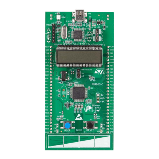
Figure 1. 32L152CDISCOVERY board
1. Picture is not contractual.
January 2017
DocID018789 Rev 4
1/38
www.st.com
1
Advertisement
Table of Contents

Related Manuals for STMicroelectronics UM1079


Summary of Contents for STMicroelectronics UM1079
-
Page 1: Figure 1. 32L152Cdiscovery Board
UM1079 User manual Discovery kits with STM32L152RCT6 and STM32L152RBT6 MCUs Introduction The STM32L152RCT6 Discovery kit (32L152CDISCOVERY) and the STM32L152RBT6 (STM32L-DISCOVERY) allow to develop applications based on the STM32L1 Series and to benefit from the ultra-low-power features of these microcontollers. The 32L152CDISCOVERY is based on an STM32L152RCT6 (256 Kbytes of Flash memory). -
Page 2: Table Of Contents
Contents UM1079 Contents Ordering information ........6 Conventions . - Page 3 UM1079 Contents Revision history ......... . . 37...
- Page 4 List of tables UM1079 List of tables Table 1. Ordering information ............6 Table 2.
- Page 5 UM1079 List of figures List of figures Figure 1. 32L152CDISCOVERY board ..........1 Figure 2.
-
Page 6: Ordering Information
Ordering information UM1079 Ordering information To order the 32L152CDISCOVERY ultra-low-power discovery board, refer to Table Table 1. Ordering information Part number Order code Description 32L152CDISCOVERY STM32L152C-DISCO Discovery kit based on STM32L152RCT6 STM32L-DISCOVERY STM32L-DISCOVERY Discovery kit based on STM32L152RBT6 1. STM32L-DISCOVERY is replaced by STM32L152C-DISCO. -
Page 7: System Requirements
UM1079 Conventions Depending on the function selected, the voltage value, the linear touch sensor position, the touchkeys status or the STM32L152RCT6 current consumption is displayed on the LCD. Table 3. Functions executed when clicking B1 button Func LED LD3/4 Value displayed on LCD... -
Page 8: Demonstration Software
Features UM1079 Demonstration software The demonstration software, preloaded in the board Flash memory, uses the built-in I measurement feature to automatically measure and display the MCU consumption on the LCD (in Run and Low-power modes).This software also allows to demonstrate touch sensing functionalities such as linear touch sensor or touchkeys. -
Page 9: Hardware And Layout
UM1079 Hardware and layout Hardware and layout The 32L152CDISCOVERY is designed around one STM32L152RCT6 packaged in an LQFP64. Figure 2 illustrates the connections between the STM32L152RCT6 microcontroller and its peripherals (ST-LINK/V2, pushbuttons, LEDs, LCD, linear touch sensor, touchkeys, and connectors). These connections are the same for the STM32L-DISCOVERY. -
Page 10: Figure 3. Top Layout
Hardware and layout UM1079 Figure 3. Top layout 1. Pin 1 of CN1, CN2, P1 and P2 connectors are identified by a square. 10/38 DocID018789 Rev 4... -
Page 11: Stm32L152Rct6 Microcontroller
UM1079 Hardware and layout Figure 4. Bottom layout 1. Pin 1 of CN1, CN2, P1 and P2 connectors are identified by a square. STM32L152RCT6 microcontroller The STM32L152RCT6 features 256 Kbytes of Flash memory, 32 Kbytes of RAM and 8 Kbytes data of EEPROM. -
Page 12: Figure 5. Stm32L152Rct6 Package
Hardware and layout UM1079 Figure 5. STM32L152RCT6 package The STM32L152RCT6 provides the following benefits: • Ultra low power proprietary 130 nm technology: speed and power consumption independent of MCU power supply, and ultra low leakage • Ultra Low power design (clock gating, low-power Flash with power-off capability):... -
Page 13: Figure 6. Stm32L152Rct6 Block Diagram
UM1079 Hardware and layout Figure 6. STM32L152RCT6 block diagram DocID018789 Rev 4 13/38... -
Page 14: Embedded St-Link/V2
Hardware and layout UM1079 Embedded ST-LINK/V2 The ST-LINK/V2 programming and debugging tool is integrated on the 32L152CDISCOVERY. The embedded ST-LINK/V2 can be used in 2 different ways according to the jumper states (see Table • Program/debug the MCU on board •... -
Page 15: Using The St-Link/V2 To Program/Debug An External Application
UM1079 Hardware and layout Figure 8. 32L152CDISCOVERY connections 4.2.2 Using the ST-LINK/V2 to program/debug an external application The ST-LINK/V2 allows also to program an STM32 device on an external application. Figure 9 shows how to remove the 2 jumpers from CN3 and to connect the external... -
Page 16: Power Supply And Power Selection
Hardware and layout UM1079 Figure 9. ST-Link connections Power supply and power selection The power supply is provided either by the host computer through the USB cable, or by an external 5 V or 3.3 V power supply. The D1 and D2 protection diodes allow to use the EXT_5V and EXT_3V pins independently... -
Page 17: Leds
UM1079 Hardware and layout By default, no battery holder is mounted on the board and SB21 and SB22 are configured in their default state (see Table 6: Solder bridges on page 21). Follow the procedure below to power the 32L152CDISCOVERYfrom the battery: •... -
Page 18: Built-In Idd Measurement Circuit
Hardware and layout UM1079 Three pairs of I/O ports are assigned to the linear touch sensor / touchkeys. Each pair must belong to the same analog switch group: • PA6, PA7 (group 2) • PC4, PC5 (group 9) • PB0, PB1 (group 3) To minimize the noise, these pairs are dedicated to the linear touch sensor / touchkeys and are not connected to external headers. -
Page 19: High Idd Range Mode
UM1079 Hardware and layout Figure 10. I measurement circuit 4.7.1 High I range mode In high I range mode, the I current is measured using the operational amplifier MAX9938FEUK+ (U5) connected to the 2 Ω shunt resistor (R21). In this case IDD_CNT_EN remains high during the measurement. -
Page 20: Ibias Current Measurement Procedure
Hardware and layout UM1079 The Q13 output of the counter allows connecting the 1 KW resistor when the current I becomes very low. Figure 11 shows how the counter and the FET transistor 1 of U20 ensure that, 150 ms after IDD_CNT_EN falling edge, the shunt resistor R22 is connected between VDD_MCU and the power supply to reduce the measurement range to 60 μA for the full scale. -
Page 21: Solder Bridges
UM1079 Hardware and layout Solder bridges Table 6. Solder bridges Bridge State Description PH0, PH1 are connected to P1 (X3, C21, C22, R30 must not be fitted). SB18,20 X3, C21, C22 and R30 provide a clock as shown in Section 7:... - Page 22 Hardware and layout UM1079 Table 6. Solder bridges (continued) Bridge State Description The BOOT0 signal of the STM32L152RCT6 is held low through a 510 Ω pull-down resistor. SB3 (BOOT0) The BOOT0 signal of the STM32L152RCT6 is held high through a 10 KΩ pull-up resistor.
-
Page 23: Lcd (24 Segments, 4 Commons)
UM1079 Hardware and layout LCD (24 segments, 4 commons) This LCD allows the STM32L152RCT6 to display any information on six 14-segment digits and 4 bars, using all COMs. (See the LCD segment mapping in Figure 17 and pin connections in... -
Page 24: Table 7. Lcd Connections
Hardware and layout UM1079 Table 7. LCD connections STM32L152RCT6 GPIO Name COM3 COM2 COM1 COM0 Name LCDSEG0 1COLON LCDSEG1 LCDSEG2 2COLON LCDSEG3 LCDSEG4 3COLON LCDSEG5 PB10 LCDSEG6 PB11 4COLON LCDSEG7 PB12 LCDSEG8 PB13 BAR2 BAR3 LCDSEG9 PB14 LCDSEG10 PB15 BAR0... -
Page 25: Extension Connectors
UM1079 Extension connectors Extension connectors The male headers P1 and P2 can connect the 32L152CDISCOVERY to a standard prototyping/wrapping board. The STM32L152RCT6 GPIOs are available on these connectors. P1 and P2 can also be probed by an oscilloscope, a logical analyzer or a voltmeter. - Page 26 Extension connectors UM1079 Table 8. MCU pin description versus board function (continued) MCU pin Board function Linear Push Main Alternate Free Touch butt LED SWD OSC P1 P2 function functions glass supp Sensor SPI1_SCK/ADC_IN 5/ DAC_OUT2/ TIM2_CH1_ETR/C OMP1_INP SPI1_MISO/ADC_I TIM3_CH1/TIM1_B...
- Page 27 UM1079 Extension connectors Table 8. MCU pin description versus board function (continued) MCU pin Board function Linear Push Main Alternate Free Touch butt LED SWD OSC P1 P2 function functions glass supp Sensor ADC_IN9/TIM3_CH LCD_SEG6/COMP 1_INP/ VREF_OUT PB2/BO TIM2_CH2/PB3/TR ACESWO/SPI1_S...
- Page 28 Extension connectors UM1079 Table 8. MCU pin description versus board function (continued) MCU pin Board function Linear Push Main Alternate Free Touch butt LED SWD OSC P1 P2 function functions glass supp Sensor SPI2_NSS/I2C2_S MBA/ USART3_CK/LCD_ PB12 SEG12/ADC_IN18/ COMP1_INP/ TIM10_CH1...
- Page 29 UM1079 Extension connectors Table 8. MCU pin description versus board function (continued) MCU pin Board function Linear Push Main Alternate Free Touch butt LED SWD OSC P1 P2 function functions glass supp Sensor TIM3_CH1/LCD_S EG24 TIM3_CH2/LCD_S EG25 TIM3_CH3/LCD_S EG26 TIM3_CH4/LCD_S...
-
Page 30: Mechanical Drawing
Mechanical drawing UM1079 Mechanical drawing Figure 13. Mechanical drawing 30/38 DocID018789 Rev 4... -
Page 31: Electrical Schematics
SLIDER_PB.SchDoc Rev C.1: - Silkscreen update for the web site: "www.st.com/stm32l152c-discovery" - MCU replacement by STM32L152RCT6 NRST Rev C.2: NRST - Replace STM32L1-DISCOVERY by STM32L152C-DISCO in title frame on all sheets STMicroelectronics Title: STM32L152C-DISCO Number: MB963 Rev: C.2(PCB.SCH) Date: 1/16/2017... -
Page 32: Figure 15. St-Link/V2 (Swd Only)
LD_BICOLOR_CMS LD3985M33R BAT60JFILM EXT_5V Vout BAT60JFILM BYPASS EXT_3V 1μF_X5R_0603 1μF_X5R_0603 USB_DM Wired on Solder Side USB_DP 100K 100nF 10nF_X7R_0603 100nF SHELL 5075BMR-05-SM 100nF 100nF 100nF 100nF STMicroelectronics Title: STM32L152C-DISCO - ST-LINK/V2 (SWD only) Number: MB963 Rev: C.2(PCB.SCH) Date: 1/16/2017 Sheet... -
Page 33: Figure 16. Mcu
BOOT0 Must be close to the Crystal BOOT0 BOOT1 VDDA VSSA VDD_1 VSS_1 100nF VDD_2 VSS_2 VDD_3 VSS_3 VDD_4 VSS_4 VDD_MCU VLCD STM32L152RCT6 100nF 100nF 100nF 100nF STMicroelectronics SB19 Title: STM32L152C-DISCO - MCU Number: MB963 Rev: C.2(PCB.SCH) Date: 1/16/2017 Sheet... -
Page 34: Lcd
Figure 17. LCD PA15 PC10 PC11 GH08172T PA10 PB15 PB14 PB13 PB12 PB10 PB11 STMicroelectronics Title: STM32L152C-DISCO - LCD Number: MB963 Rev: C.2(PCB.SCH) Date: 1/16/2017 Sheet... -
Page 35: Figure 18. Idd Measurement
Figure 18. I measurement IDD Measure VDD_MCU IDD_Measurement MAX9938FEUK+ 74H1G66STR 2(1%) 1K(1%) 74LX1G04CTR 100nF IDD_CNT_EN IDD_WAKEUP PC13 SB14 M74HC4060TTR STS4DPF20L Oscillator frequency 30KHz STMicroelectronics Title: STM32L152C-DISCO - IDD_Measurement Number: MB963 Rev: C.2(PCB.SCH) Date: 1/16/2017 Sheet... -
Page 36: Figure 19. Linear Touch Sensor/Touchkeys
100nF GRP 2 GRP 9 GRP 3 USER & WAKE-UP Button 47nF 47nF 47nF Not Fitted SLIDER 3 Positions 100K NRST NRST 100nF RESET Button STMicroelectronics Title: STM32L152C-DISCO - Linear Sensor and Buttons Number: MB963 Rev: C.2(PCB.SCH) Date: 1/16/2017 Sheet... -
Page 37: Table 9. Document Revision History
UM1079 Revision history Revision history Table 9. Document revision history Date Revision Changes 10-May-2011 Initial release. Added Chapter 6: Mechanical drawing. 24-June-2011 Modified Chapter 4.3: Power supply and power selection. Added 32L152CDISCOVERY, related features. Updated STM32L-DISCOVERY url. Modified Section 2.2: System requirements, Section 2.5: Order codes, Section 4.1: STM32L152RBT6 or STM32L152RCT6... - Page 38 IMPORTANT NOTICE – PLEASE READ CAREFULLY STMicroelectronics NV and its subsidiaries (“ST”) reserve the right to make changes, corrections, enhancements, modifications, and improvements to ST products and/or to this document at any time without notice. Purchasers should obtain the latest relevant information on ST products before placing orders.
Need help?
Do you have a question about the UM1079 and is the answer not in the manual?
Questions and answers