Table of Contents
Advertisement
Quick Links
Congratulations on your acquisition of Maxford USA's Nieuport 28 ARF
The Nieuport 28 was a French biplane fighter flown during World War I, designed by Gustave Delage and built by Nieuport,
also known as Nieuport-Delage – a French airplane company famous for racers before World War I and fighter aircraft during
World War I and between the wars.
Retaining many of the Nieuport 17's best features, the Nieuport 28 was a lightly built, highly maneuverable fighter: It had a
more powerful engine; carried twin synchronized machine guns; its ailerons were fitted only to the lower wing; and it had two-
spar wings – top and bottom – in place of the earlier Nieuport types' sesquiplane (a biplane with one long wing and one short one
above or below it).
The Nieuport 28 was the first aircraft to see service in any American fighter squadron. By the time the Nieuport 28 became
available in early 1918, it was already considered "surplus" from the French point of view. Their SPAD XIII was a superior
aircraft in most respects and had already become firmly established as the standard French fighter. (A 1/5-scale ARF SPAD XIII
is also available from Maxford USA at www.maxfordusa.com.)
When the Nieuport 28 was offered to the United States, it was immediately accepted by the American Expeditionary Force,
and 297 Nieuport 28s were put into service in the 27
Several well-known WWI American pilots, including 26-victory American ace Captain Eddie Rickenbacker and Lieutenant
Quentin Roosevelt – the youngest son of former President Theodore Roosevelt – flew Nieuport 28s.
Sadly, on July 14, 1918, just 4 months before his 21
lines, felled by two machine gun bullets which struck him in the head. His body was buried at the crash site by the Germans.
Twenty-six years later, following the World War II D-Day invasion of France, Quentin's brother, Brig. Gen. Theodore Roosevelt,
Jr. died of a heart attack on July 12, 1944 and was buried at the Omaha Beach War Memorial. Quentin's remains were then
reinterred beside his elder brother.
This model of the Nieuport 28 is a new design with improvements over previous products. It is constructed mainly of laser-cut
balsa and light ply, finished with a Mylar film covering patterned after the aircraft flown by 94th Aero Squadron's ace pilot Eddie
Rickenbacker, and may be special-ordered with the option of a flat-finish or as a fabric-covered prepainted ARF.
We invite you to enjoy the pride of ownership and the joy of flying your high-
quality balsa and light-ply almost-ready-to-fly version of this historic aircraft.
Entire contents – Copyright 2015
1
/
5
N
I
E
1
/
5
N
I
E
R
A
D
I
O
C
O
N
T
R
R
A
D
I
O
C
O
N
T
I
N
S
T
R
I
N
S
T
R
th
, 94
U
P
O
R
T
U
P
O
R
T
O
L
W
W
I
M
O
D
R
O
L
W
W
I
M
O
D
U
C
T
I
O
N
M
A
U
C
T
I
O
N
M
A
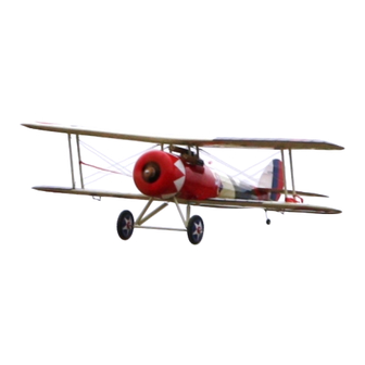
NOTE: Shown with windshield, WWI pilot figure,
scale machine guns, motor and propeller. These
optional items are not included with the ARF.
th
th
rd
, 95
and 103
Aero Pursuit Squadrons.
st
birthday, Lieutenant Roosevelt's Nieuport 28 was downed behind enemy
Page 1 of 17
2
8
A
R
F
2
8
A
R
F
E
L
A
I
R
P
L
A
N
E
E
L
A
I
R
P
L
A
N
E
N
U
A
L
N
U
A
L
Copyright 2015 - N28 / S160127
!
Advertisement
Table of Contents

Subscribe to Our Youtube Channel
Related Manuals for Maxford USA NIEUPORT 28 ARF


Summary of Contents for Maxford USA NIEUPORT 28 ARF
- Page 1 These optional items are not included with the ARF. Congratulations on your acquisition of Maxford USA’s Nieuport 28 ARF The Nieuport 28 was a French biplane fighter flown during World War I, designed by Gustave Delage and built by Nieuport, also known as Nieuport-Delage –...
-
Page 2: Table Of Contents
4. Throughout the lifetime of this model, use only the Maxford USA-recommended or same-sized engine or motor and a new or well-maintained radio control system and batteries recommended by the maker of your motor and radio system. -
Page 3: Warranty, Liability Waiver, And Return Policy
II. WARRANTY, LIABILITY WAIVER, AND RETURN POLICY Maxford USA guarantees this kit to be free from defects in material and workmanship at the time of purchase. All of our products have been inspected in our factory and are checked again when shipped from our warehouse. -
Page 4: Special Features Of This Nieuport 28 Model
3. Returned merchandise that is accepted by Maxford USA for credit is subject to a 10% to 20% restocking fee (the final amount will be determined by Maxford USA upon receipt and examination of the returned merchandise). -
Page 5: Assembly Photo-Instructions
2. Items included with this Nieuport 28: Precovered fuselage, upper and lower-wing panels and upper-wing’s center section, vertical and horizontal stabilizers, rudder and elevator halves, with all hinge openings precut. Prepainted fiberglass cowl. Rudder pull-pull cables and aileron and elevator pushrods. ... - Page 6 7. Using a total of 4 wheel collars, attach both main wheels to the landing gear’s axles with wheel collars and secure with threadlock. 8. Test-fit the hatch: (1) Lift the rear of the hatch above the magnet and toward the rear; (2) Lift the front and maneuver the hatch’s corners to clear the edge cockpit.
- Page 7 d. While continuing to direct the pushrod toward the tail, guide the straws and prongs straight back at the same time. (NOTE: Do attempt to pull the straws or the prongs outward, away from the PULL STRAIGHT BACKWARD fuselage.) (TOWARD THE TAIL) e.
- Page 8 24. Use epoxy to secure the vertical stabilizer into the opening in the horizontal stabilizer and to the vertical post at the rear of the fusealge. Use masking tape to securely hold the vertical stabilizer until the epoxy is cured fully. 25.
- Page 9 40. Using the preformed cabane mounting ‘pockets’ in the fuselage, test-fit the cabane struts Wooden cabane (packaged in plastic bags marked F for front and R for rear) and their corresponding front strut brace and rear metal mounting plates to the fuselage. (NOTE: Align the holes in the cabane mount- ing plates with the holes in the cabane struts and with openings for the blind nuts that have...
- Page 10 50. Slide the upper wing’s wing tubes midway through the upper wing’s center section, then slide the left and right upper wing panels onto their wing tubes. 51. Carefully guide the wing struts over their mounting tabs in the bottom of both left and right panels of the top wing. Use bolts and nuts to secure all four wing struts onto their tabs in the top and bottom wing panels.
- Page 11 Warning: As you guide the wing wires between the numbered anchor points, adjust the tension on each segment of the wire to ensure the wing panels do not become warped. Although these wing wires are mostly cosmetic, it is possible for uneven tension on the wing wires to warp the wings, causing the airplane to not be safely controllable in flight.
- Page 12 63. Cut and remove the excess wire. If necessary, adjust the clevises to ‘snug’ the wing wires. 64. With the wing wires positioned and the tension equally adjusted, secure each wing wire by ‘snugging’ the brass rod’s lock nut against its clevis, then secure each rod to its clevis by applying epoxy or CA adhesive onto the rod’s threads at each nut and inside each clevis.
- Page 13 71. If you are using a gas or glow engine, install the supplied fuel tank inside the engine mounting box. Route all appropriate fuel lines (such as the ‘clunk’ line to the carburetor, vent line, and a line to fill the tank). If you are using a gas engine, you may also install a safety ‘kill’...
- Page 14 82. When you are content with the size of the openings and fit of the dummy engine, secure the dummy engine inside the cowl with epoxy. 83. If you will install an optional windshield, free the windshield from its molding- flash, then test fit and trim the windshield to fit in front of the cockpit.
-
Page 15: Setup And Adjustments
As shown at the right, the dashboard’s openings are cut to fit Maxford USA’s heavy duty ‘DSC Switch with Charge Jack.’ (NOTE: This 8A switch includes a built-in charge jack, mounting plate, screws, wire leads and connectors. -
Page 16: Preparation For Transport And Field Setup
4. If you are using a Computer Radio: For initial flights set all linkages for near-max. possible deflections; then, soften the aileron’s and elevator’s control throws by selecting 60% or more exponential (use 30% exponential for the rudder). Initial settings if you are using a Non-Computer Radio: Low rates High rates Ailerons .... - Page 17 A T O Y PLEASE ENJOY YOUR HOBBY AND FLY SAFELY! Designed by: Maxford USA RC Model Mfg., Inc. Distributed by: Maxford USA RC Model Distribution, Inc. 15939 Illinois Avenue #C Telephone (voice) ..... (562) 529-3988 Paramount, CA 90723 Fax ........(562) 529-6988 Toll free (orders only) ..
Need help?
Do you have a question about the NIEUPORT 28 ARF and is the answer not in the manual?
Questions and answers