Table of Contents
Advertisement
Quick Links
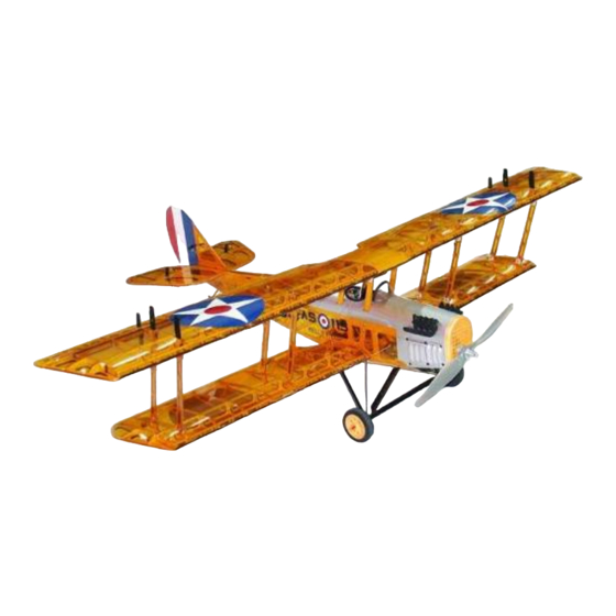
50" Curtis Jenny Electric Scale ARF
Instruction Manual
Specs:
Wing Span: 50"
Overall length: 33"
Wing area: 364 sq. in
Ready to fly weight: 34 oz
Motor/Engine:
Electric: Uranus-35425 brushless outrunner motor, Prop: EP 11x6, 12x6
Glow: .15-.21 glow engine, Prop: 8x4, 9x4, fuel tank: 100 ml (about 3.4 oz)
Radio required: 4ch, 4-5 mini servos
Advertisement
Table of Contents

Related Manuals for Maxford USA 50” Curtis Jenny ARF


Summary of Contents for Maxford USA 50” Curtis Jenny ARF
-
Page 1: Instruction Manual
50” Curtis Jenny Electric Scale ARF Instruction Manual Specs: Wing Span: 50" Overall length: 33" Wing area: 364 sq. in Ready to fly weight: 34 oz Motor/Engine: Electric: Uranus-35425 brushless outrunner motor, Prop: EP 11x6, 12x6 Glow: .15-.21 glow engine, Prop: 8x4, 9x4, fuel tank: 100 ml (about 3.4 oz) Radio required: 4ch, 4-5 mini servos... -
Page 2: Return Policy
Maxford USA provides high quality, thoroughly tested model airplane kits, but ultimately the quality and capability of your finished model airplane depends on how you build it. Maxford USA can NOT in any way guarantee the performance of your finished model airplane. -
Page 3: Lithium Battery Handling & Usage
3. Take time to build straight, TRUE and STRONG. 4. Maxford USA recommends that you use a good quality radio system and our recommended or same sized good quality motor and components throughout the building process. -
Page 4: Before You Begin
Before you begin: -Read the instructions completely before beginning assembly. -Don’t work when tired. Many aircraft (including full sized ones) have crashed because of errors made by tired builders. -Always work in a well ventilated and lighted area. ©2008 Maxford USA www.maxfordusa.com... - Page 5 Do not crush the wood under the screw. Place a small drop of thin CA at the end of the screw and nut. Rudder lines come through rear bulkhead. Elevator lines come through the edge of the closer bulkhead. ©2008 Maxford USA www.maxfordusa.com...
- Page 6 (pull back the spring to open the clevis). Each control line is inserted first through a narrow, 1cm-long crimp tube, then through the hole in the brass pullrod, iii. then back the other way through the crimp tube, ©2008 Maxford USA www.maxfordusa.com...
- Page 7 Prepare the elevator control lines per the control-line guidelines above. e) Tighten each of the lower elevator lines then crimp the tube over the line. f) Remove clamps and balsa from the elevators. Remove the shims or blocks holding the servo arm. ©2008 Maxford USA www.maxfordusa.com...
-
Page 8: Aileron Servo Installation
-Slide the e/z link onto the servo linkage. Carefully measure the linkage and make a 90° bend into the control horn. Insert the link into the control horn and the e/z link. Trim as needed. ©2008 Maxford USA www.maxfordusa.com... -
Page 9: Radio Installation
Mount the arm onto the servo. -Repeat for the elevator servo. Make sure the cables have clean runs inside the fuselage and are not tangled. -Attach the clevises to the elevator and rudder control horns. ©2008 Maxford USA www.maxfordusa.com... - Page 10 -It helps make the model look nice if y ou paint or stain the balsa in the cockpit area. ©2008 Maxford USA www.maxfordusa.com...
-
Page 11: Engine Attachment
-Carefully slide the fuselage through the wings from the back. It helps to turn the fuselage about 30° and straighten it when in position. -Temporarily insert and a ttach one nylon screw into the wing trailing edge attachment. Do not fully tighten yet. ©2008 Maxford USA www.maxfordusa.com... - Page 12 -Tighten all wing and cabane strut bolts. Put a drop of thread lock on t hem. -Attach the aileron servo leads to the aileron arness. -You may add two pilot figures if you want. ©2008 Maxford USA www.maxfordusa.com...
-
Page 13: Landing Gear
-Remove the wing root attachment screw you previously inserted during the wing/fuselage assembly. -Attach the landing gear using 4 nylon screws and tighten. ©2008 Maxford USA www.maxfordusa.com... - Page 14 (There should also be two small holes poked into the covering material.) -Insert the 2 carbon fiber ro ds into the blocks and glue the m into place. ©2008 Maxford USA www.maxfordusa.com...
-
Page 15: Final Check Before Flying
-If possible, have another modeler check your Jenny over. Smart pilots never mind a second opinion. Hopefully you will never need them, but for replacement parts check our web site at www.maxfordusa.com ©2008 Maxford USA www.maxfordusa.com... - Page 16 DBA: Green RC Models USA Address: 13909 Artesia Blvd., Cerritos, CA 90703 Tel: 562-802-0680 Fax: 562-802-0650 Web site: www.maxfordusa.com Special thanks for Thayer Syme, Managing Editor, Fly RC Magazine Steven Kessinger, Commercial Pilot Jim Fallon, Maxford USA value customer ©2008 Maxford USA www.maxfordusa.com...
Need help?
Do you have a question about the 50” Curtis Jenny ARF and is the answer not in the manual?
Questions and answers