Advertisement
Table of Contents
- 1 Table of Contents
- 2 Important Safety Precautions & Assembly Tips
- 3 Warranty, Liability Waiver, and Return Policy
- 4 Special Features of this Nieuport 28 Model
- 5 Specifications
- 6 Parts List
- 7 Assembly Photo-Instructions
- 8 Setup and Adjustments
- 9 Preparation for Transport and Field Setup
- 10 Preflight Checks
- Download this manual
1
1
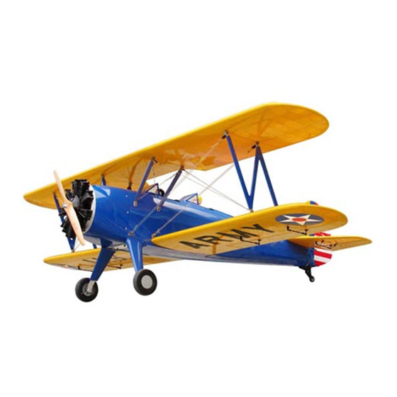
Shown with optional upgraded scale dummy
engine, electric motor and propeller.
Congratulations on your acquisition of a Maxford USA ARF PT-17 Stearman
The PT-17 is a biplane that was used as a military trainer by the US Army Air Corps during the 1930s and served throughout
WWII. The PT-17 is also widely known as the Stearman, Boeing Stearman, Boeing Model 75, or the Kaydet. At least 9,783 were
built and thousands of surplus PT-17s were sold on the civil market after the conflict.
This almost-ready-to-fly radio-control version of the PT-17 is based on the aircraft that is owned by John Mohr, who very
kindly sent us many detailed pictures of his personal aircraft. We also acknowledge and thank Jay Smith, editor or Model
Aviation, for his help and advice on this project.
This model is constructed mainly of laser-cut balsa and light plywood. As shown above, it is finished with a Mylar film
covering. It may also be special-ordered with a flat-finish Mylar or as a fabric-covered and prepainted ARF.
We invite you to enjoy the pride of ownership and the joy of flying your high-
quality balsa and light-ply almost-ready-to-fly version of this historic aircraft.
I.
II.
IV. Specifications ..................................................... 4
V.
Parts List ............................................................. 4
Entire contents - Copyright 2014
/
5
P
T
-
1
7
/
5
P
T
-
1
7
R
A
D
I
O
C
O
N
T
R
A
D
I
O
C
O
N
T
I
N
S
T
R
I
N
S
T
R
TABLE OF CONTENTS
S
T
E
A
R
M
S
T
E
A
R
M
R
O
L
L
E
D
M
O
D
E
R
O
L
L
E
D
M
O
D
E
U
C
T
I
O
N
M
A
U
C
T
I
O
N
M
A
VI.
Assembly photo-instructions .......................... 5
VII. Setup and adjustments .................................. 17
IX.
Preflight checks ............................................ 18
1
Page
of 18
A
N
A
R
F
A
N
A
R
F
L
A
I
R
P
L
A
N
E
L
A
I
R
P
L
A
N
E
N
U
A
L
N
U
A
L
Copyright 2015 - PT17 / S150209
!
Advertisement
Table of Contents

Related Manuals for Maxford USA 1/5 PT-17 STEARMAN ARF


Summary of Contents for Maxford USA 1/5 PT-17 STEARMAN ARF
-
Page 1: Table Of Contents
Congratulations on your acquisition of a Maxford USA ARF PT-17 Stearman The PT-17 is a biplane that was used as a military trainer by the US Army Air Corps during the 1930s and served throughout WWII. -
Page 2: Important Safety Precautions & Assembly Tips
4. Throughout the lifetime of this model, use only the Maxford USA-recommended or same-sized engine or motor and a new or well-maintained radio control system and batteries recommended by the maker of your motor and radio system. -
Page 3: Warranty, Liability Waiver, And Return Policy
II. WARRANTY, LIABILITY WAIVER, AND RETURN POLICY Maxford USA guarantees this kit to be free from defects in material and workmanship at the time of purchase. All of our products have been inspected in our factory and are checked again when shipped from our warehouse. -
Page 4: Special Features Of This Nieuport 28 Model
Pliers, Allen wrenches, a high speed rotary tool, scissors and masking tape. 90 to 120 glow engine, or an equivalent-powered motor system. (See http://www.maxfordusa.com/brushlessmotorandcontroller.aspx for detailed information about Maxford USA electric power systems.) Propeller. Five standard-sized servos (four standard servos if you use an electric power... -
Page 5: Assembly Photo-Instructions
2. Items included with this PT-17: Prepainted plastic dummy radial engine. Wing-rod joiners, preformed cabanes and struts, and all required control horns, hinges, linkages, Precovered fuselage, upper and lower-wing wing wires, tail braces and related hardware. panels, upper-wing‟s center section, vertical ... - Page 6 6. Test-fit the dummy engine over your electric Shown with an motor or glow engine and to the PT-17‟s nose electric motor and adjust the depth of the engine mounting box in the fuselage to position the propeller for a minimum of -inch clearance in front of the dummy engine as shown at the right.
- Page 7 Maxford USA servo-extension safety clip to secure the extension to your tailwheel servo‟s lead.) 26.
- Page 8 33. Ensure good wood-to-wood glueing surfaces between the vertical stabilizer and fuselage by removing the Mylar from the parts of the horizontal stabizer that will be captured inside this opening as pictured below. 34. Use 30 minute epoxy to secure the vertical stabilizer into its opening in the fusealge.
- Page 9 47. Use the hardware provided with a standard-sized servo to install your rudder servo in the front/lower opening of the servo tray as shown below. 48. Align the rudder to your elevator servo‟s output arm. Attach the rudder‟s pull-pull cables to the rudder servo using your choice of either of the methods described below: a) Draw the cables snug and use crimp tubes, as b) Draw the cables snug and use crimp tubes with threaded...
- Page 10 60. Hold your elevator at neutral (on the same level as the horizontal stabilizer) and tighten the EZ Link connector onto the elevator pushrod. 61. If necessary, cut off the portion of the elevator pushrod that extends excessively behind the elevator servo‟s EZ Link connector.
- Page 11 64. You may opt to connect a UBEC to your flight battery or carry a receiver battery to power your radio system. If you use a battery for your radio system and if you are not using the optional cockpit dashboards: Use scrap wood (such as popsicle sticks) to mount your radio-system‟s power switch where it is easily accessible from inside either of the cockpits.
- Page 12 72. Apply masking tape to hold each aileron aligned with its adjoining wing panel. 73. Select servo output arms long enough to extend fully beyond the outer surface of the aileron hatch covers as shown at the right. 74. Attach an EZ Link connector to the outermost hole in each servo output arm.
- Page 13 86. Securely attach the cabane struts to the sides of the fuselage with -inch (15mm) wood screws. 9/16 87. Slide the lower wing panels onto their wing rods. As each wing panel nears the fuselage: Connect an aileron-servo extension to the end of the aileron‟s Front (leading edge) of the Y-harness and guide the Maxlok tab at the wing panel‟s top wing’s center section...
- Page 14 95. Use wood screws to attach wing-wire anchors (#1 in the diagram shown below) near the fuselage at the leading edges of both lower wing panels. Apply thin CA adhesive to harden the holes for these wing-wire anchor Wing wire’s clevis connects at screws.
- Page 15 101. Attach a clevis and threaded rod at anchor point #6. Uses crimp tubes to install the remaining left-side wing wire(s) from anchor points 6 through 8. 102. In the same manner as used for the left-side wires, install wing wire(s) between the Plastic anchor point right side‟s wing panels.
- Page 16 112. Using the openings in the template (shown below), make 4 narrow cuts to receive the 4 tabs in each windshield. Set aside the template and test-fit a windshield in front of each cockpit. Template’s 4 slotted openings 113. Use epoxy or windshield adhesive to secure the windshields in position.
-
Page 17: Setup And Adjustments
122. As shown at the bottom of the preceding page, align each hubcap‟s round post to the round opening in the hub of each wheel. Press the retaining clip at the end of the two remaining posts into their rectangular openings in the hubs. (NOTE: A conservative modeler may also apply epoxy to ensure the hubcaps remain attached to their wheels.) 123. -
Page 18: Preflight Checks
A T O Y PLEASE ENJOY YOUR HOBBY AND FLY SAFELY! Designed by: Maxford USA RC Model Mfg., Inc. Distributed by: Maxford USA RC Model Distribution, Inc. 15939 Illinois Avenue #C Telephone (voice) ..... (562) 529-3988 Paramount, CA 90723 Fax ........(562) 529-6988 Toll free (orders only) ..
Need help?
Do you have a question about the 1/5 PT-17 STEARMAN ARF and is the answer not in the manual?
Questions and answers