Advertisement
Quick Links
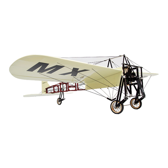
1/6 SPORT-SCALE ARF R/C MODEL AIRPLANE
I
N
S
T
I
N
S
T
The above photo shows an optional U35425 motor, propeller,
On July 25, 1909, French aviator, inventor and engineer Louis Charles Joseph Blériot (pictured at
below center) made the first flight across the English Channel in a heavier-than-air aircraft, a Blériot XI.
This historic achievement not only won Blériot a lasting place in history but assured the future of his
aircraft manufacturing business. The Blériot XI was eventually sold with various wingspans and as
single- and two-seat versions, marketed as trainers, sport/touring, military, and racing/exhibition
aircraft with several different types of engine, including the famous Anzani 3-cylinder fan (or semi-
radial) engine. Like its predecessor, it was a tractor-configuration monoplane, with a partially covered
box-girder fuselage built from ash with wire cross bracing.
Harriet Quimby (pictured at above right) was America's first licensed woman pilot. In 1912 she flew
a Blériot XI from England to France across the English Channel. The first Blériot XIs entered military
service in Italy and France in 1910, and a year later, some of those were used in action by Italy in North
Africa – the first use of an aircraft in a war – and in Mexico. The Royal Flying Corps received its first
Blériots in 1912. During the early stages of the First World War, eight French, six British and six Italian
squadrons operated various military versions of the aircraft, mainly in observation duties, but also as
trainers, and in the case of single-seaters, as light bombers with a bomb load of up to 25 kilograms, just
over 55 pounds in traditional American units.
Copyright 2013: Maxford USA
B
l
é
r
B
l
é
r
R
U
C
T
R
U
C
T
dummy engine and simulated vintage-style spoked wheels.
i
o
t
X
i
o
t
X
I
O
N
M
I
O
N
M
1
of 16
Page
I
I
A
N
U
A
A
N
U
A
Blériot XI: S130926
L
L
Advertisement

Subscribe to Our Youtube Channel
Related Manuals for Maxford USA Bleriot XI


Summary of Contents for Maxford USA Bleriot XI
- Page 1 25 kilograms, just over 55 pounds in traditional American units. of 16 Copyright 2013: Maxford USA Page Blériot XI: S130926...
- Page 2 4. Throughout the lifetime of this model, use only the Maxford USA-recommended power system and a new or well-maintained radio-control system.
- Page 3 Maxford USA from all current or future liability for any personal injury, property damage, or wrongful death, and if you (the buyer or user of this product) are involved in any claim or suit, you will not sue Maxford USA or any of its representatives.
- Page 4 3. Returned merchandise that is accepted by Maxford USA for credit is subject to a 10% to 20% restocking fee (the final amount will be determined by Maxford USA upon receipt and examination of the returned merchandise).
- Page 5 Right end of the horizontal tailplane. the horizontal tailplane. Right-side elevator’s torque rod of 16 Copyright 2013: Maxford USA Page Blériot XI: S130926...
- Page 6 (3 cm) long bolt, matching self-locking nuts and 3/16- approx. -inch (13 mm) tall plastic spacer. NOTE: Do not shorten the approx. 1 inch (3 cm) long bolt. 3/16- of 16 Copyright 2013: Maxford USA Page Blériot XI: S130926...
- Page 7 You may learn more about optional spoked wheels at http://www.maxfordusa.com/wheels.aspx.) 21. Twist a tailwheel steering horn fully onto the bolt on the tailwheel strut. of 16 Copyright 2013: Maxford USA Page Blériot XI: S130926...
- Page 8 CA adhesive is still wet, align and hold the rudder’s metal pushrod next to the tailwheel’s composite steering-control rod and slide the heat-shrink tubing back toward the tail, covering both pushrods. of 16 Copyright 2013: Maxford USA Page Blériot XI: S130926...
- Page 9 4. Select and install servo arms for your aileron servos that are long enough that servo arm travel will not be limited and attach an EZ Link connector to the outer hole on each aileron servo’s arm. Copyright 2013: Maxford USA Page of 16 Blériot XI: S130926...
- Page 10 -inch (1 cm) 5/16 screws. 20. Insert the ends of the upper wing- wire-mounting braces that have the smaller predrilled holes into the four slotted openings in the top of the fuselage. of 16 Copyright 2013: Maxford USA Page Blériot XI: S130926...
- Page 11 ESC. Guide the ESC’s battery connector toward the battery tray and guide the ESC’s servo-type connector into the cockpit in front of the rudder and elevator servos. Copyright 2013: Maxford USA Page of 16 Blériot XI: S130926...
- Page 12 Attach a spring to the same anchor point used for the already connected lower end of the landing-gear’s spring. Attach one end of a spring to anchor point at bottom of landing gear. Copyright 2013: Maxford USA Page of 16 Blériot XI: S130926...
- Page 13 Tie one end of the simulated wing wire to the free end of the spring at the rear left of the upper wing-wire-mounting brace (G in the diagram at the top of the following page). Copyright 2013: Maxford USA Page of 16 Blériot XI: S130926...
- Page 14 40 and exchanging the words ‘left’ and ‘right’ where necessary. 42. Ensure all nuts, screws and EZ Link connectors are securely tightened and apply threadlock compound to secure all metal-to-metal connections. Congratulations! Assembly is finished! Copyright 2013: Maxford USA Page of 16 Blériot XI: S130926...
- Page 15 3. Servo end-point adjustments: If you are using a Computer Radio, for initial flights set the elevator, rudder and aileron linkages for near-maximum-possible deflections and use your transmitter to add some ‘exponential’ to soften the control throws around center. of 16 Copyright 2013: Maxford USA Page Blériot XI: S130926...
- Page 16 Any testing, flying and use of this model airplane is done entirely at your own risk. PLEASE ENJOY YOUR HOBBY AND FLY SAFELY! Manufactured by: Maxford USA RC Model Mfg, Inc. Distributed by: Maxford USA RC Model Distribution, Inc. Telephone (voice) ......(562) 529-3988 15939 Illinois Avenue, #B-C Fax ..........
- Page 17 5-minute epoxy is used to secure the installation kit to the cockpit floor and the pilot seat to the top of the installation kit. If you did not purchase the pilot seat with a preinstalled Maxford USA pilot figure, glue the pilot figure of your choice in the seat.
- Page 18 Apply CA adhesive to securely anchor the knot in the cross-bracing wire at the hole in the rudder post. Trim off the loose ends of the cross-bracing wire at the knot. Copyright 2013: Maxford USA Page of 4 Blériot XI: S130926...
- Page 19 ‘wire’ up and through the hole on the right side of the top of the tail boom. l. Guide the ‘wire’ down into the hole in the right-rear of the horizontal tailplane. of 4 Copyright 2013: Maxford USA Page Blériot XI: S130926...
- Page 20 Insert the end of a ‘wire’ into the hole in the right-front of the horizontal tailplane. Pull the wire snug and form a knot ‘wire.’ v. Apply CA adhesive to the knots. Trim off the loose ends of excess ‘wire.’ of 4 Copyright 2013: Maxford USA Page Blériot XI: S130926...
Need help?
Do you have a question about the Bleriot XI and is the answer not in the manual?
Questions and answers