Table of Contents
Advertisement
2
2
V
.
V
.
E
R
E
R
S
E
N
S
E
N
S
P
O
R
T
-
S
S
P
O
R
T
-
S
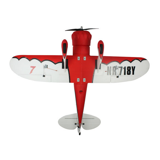
The Gee Bee Model Y Senior Sportster was one of the famous "Golden Age" racers created by
Granville Brothers Aircraft in the early 1930s. It was a low-wing, strut-and-wire-braced
monoplane with open cockpits. To a great extent, it was an enlarged, two-seat version of the
single-seat Sportster. Only two were ever built; both were unfortunately destroyed in accidents.
This radio-controlled almost-ready-to-fly (ARF) 27% sport-
scale model is based on the full-scale Gee Bee Model Y Senior
Sportster. It comes 99% preassembled by our factory, includes
a prepainted fiberglass cowl and wheel pants, and includes a
spring-loaded tail wheel to aid in ground handling.
We invite you to enjoy the pride of ownership and the joy of flying this beautiful ARF
sport-scale model aircraft.
Table of Contents:
......................................................
I.
II.
................................................................
III.
...................................................
IV.
V.
Copyright Maxford USA 2017
2
7
%
G
2
7
%
G
I
O
R
I
O
R
C
A
L
E
A
R
F
C
A
L
E
A
R
F
...................
...........
E
E
B
E
E
E
E
B
E
E
S
P
O
R
S
P
O
R
R
/
C
M
O
D
R
/
C
M
O
D
2
VI.
2
VII.
2
VIII.
3
IX.
3
X.
Page 1
of 14
M
O
D
E
M
O
D
E
T
S
T
E
T
S
T
E
E
L
A
I
R
P
L
E
L
A
I
R
P
L
..............................
............................................
L
Y
L
Y
R
R
A
N
E
A
N
E
........................
3
4
....
5
........................
6
13
S171108
Advertisement
Table of Contents

Subscribe to Our Youtube Channel
Related Manuals for Maxford USA Gee Bee Model Y Senior Sportster


Summary of Contents for Maxford USA Gee Bee Model Y Senior Sportster
-
Page 1: Table Of Contents
The Gee Bee Model Y Senior Sportster was one of the famous “Golden Age” racers created by Granville Brothers Aircraft in the early 1930s. It was a low-wing, strut-and-wire-braced monoplane with open cockpits. To a great extent, it was an enlarged, two-seat version of the single-seat Sportster. -
Page 2: Specifications
Propeller ................... 20- to 22-inch diameter by 8- to 10-inch pitch or as recommended by the maker of your power system (Dimensions and weights are approximate.) II. IMPROVEMENTS IN THIS NEW VERSION BY MAXFORD USA More robust landing-gear struts. -
Page 3: Special Features
Center the wing rod in the fuselage. Slide each wing panel toward the fuselage and reconnect the aileron servo extensions and optional Maxford USA servo-extension safety clips. If the top-side wing struts are not glued in, insert the upper wing struts into their openings in the top of the wing. Guide the upper wing struts into their slots on each side of the fuselage. -
Page 4: Safety Precautions & Assembly Tips
If you have any question or concern about the instructions, before you proceed with assembly of this product, contact your dealer or speak to a Maxford USA customer service representative at 562-529-3988 (Monday through Friday, except national holidays, 9 AM to 5 PM Pacific Time). -
Page 5: Limited Warranty, Liability Waiver & Return Policy
VIII. LIMITED WARRANTY, LIABILITY WAIVER & RETURN POLICY Maxford USA guarantees this ARF kit to be free from defects in material and workmanship at the time of purchase. Our products have been inspected in our factory and are checked again when shipped from our warehouse. -
Page 6: Photo Instructions And Assembly Notes
3. Returned merchandise that is accepted by Maxford USA for credit is subject to a 10% to 20% restocking fee (the final amount will be determined by Maxford USA upon receipt and examination of the returned merchandise). - Page 7 Align the slots in the outer surfaces of the wheel pants with the landing- gear’s struts, then gently guide and push the struts out through the slots as pictured at the far right. Copyright Maxford USA 2017 Page 7 of 14 S171108...
- Page 8 We recommend using optional Maxford USA servo-extension safety clips as pictured above.) Align the wing panels to their fairings on the fuselage and the alignment pins in the root ribs to their openings on the fuselage.
- Page 9 Connect the rudder’s and elevator’s servo exten- sions, secure these connections with optional Maxford USA servo-extension safety clips, guide the extensions forward through the fuselage, and Rudder-servo connect them to your receiver.
- Page 10 Reinforce the guide holes with thin CA adhesive and install three wood screws as pictured on the following page and adjust the screws and position the magnets as instructed below and on page 5 of this manual. Copyright Maxford USA 2017 Page 10 of 14...
- Page 11 Permanently glue the single-ended NOTE: Face the notches OUTWARD metal wing wire anchors into their toward the wing tips openings in the bottoms of the wing panels as pictured at the right. Copyright Maxford USA 2017 Page 11 of 14 S171108...
- Page 12 Guide the ends of the wire back into and fully through the crimp tube, then position the crimp tube approx. 1- to 2-inches from the spring. (Do NOT crimp the tubes at this time.) Copyright Maxford USA 2017 Page 12 of 14...
-
Page 13: Initial Setup & Adjustments
-inch (18 degrees) at the trailing edge, up & down from center. Rudder ....1-inch (18 degrees) at the trailing edge, left & right from center. (NOTE: If you mix rudder with your ailerons, begin with an aileron-to-rudder mix of 40 to 50%.) Copyright Maxford USA 2017 Page 13 of 14... - Page 14 RC hobby items online at www.maxfordusa.com. Maxford USA RC Model Mfg., Inc. is a rapidly growing importer and distributor of radio- controlled model airplanes. Our mission is to provide better RC products and services for our customers.
Need help?
Do you have a question about the Gee Bee Model Y Senior Sportster and is the answer not in the manual?
Questions and answers