Table of Contents
Advertisement
Quick Links
1
/
1
/
I
N
S
I
N
S
The Albatros D.III was a single-seat biplane used by the Imperial German Army Air Service and the Austro-Hungarian
Air Service during the First World War. It was heavily armed with twin synchronized, forward-firing 7.92 mm LMG
08/15 machine guns and powered by a 180 hp Mercedes 6-cylinder inline, water-cooled engine (unusual for the time), and
its streamlined radiator, mounted on the top wing, was offset slightly to starboard so that combat damage would not result
in scalding water being released over the pilot. The prototype first flew in August 1916 and was quickly recognized for its
outstanding maneuverability and rate of climb. Like most fighters, the Albatros was prone to spinning. However, its
recovery was straightforward, and German aces including Manfred von Richthofen, Ernst Udet, Erich Löwenhardt,
Kurt Wolff, and Karl Emil Schäfer credited the D.III as being both pleasant and easy to fly.
The Albatros D.Va was the final development of the Albatros D.I family, and the last Albatros fighter to see
operational service. The D.V entered service in May 1917 and, like the D.III before it, immediately began experiencing
structural failures of the lower wing. Indeed, anecdotal evidence suggests that the D.V was even more prone to wing
failures than the D.III. Albatros responded with the D.Va, which featured stronger wing spars, heavier wing ribs, and a
reinforced fuselage.
The Maxford USA 40-inch Albatros D.III was the 1
nd
Albatros D.Va is our 2
We invite you to enjoy the pride of ownership and the joy of flying this
beautiful ARF sport-scale model of the famous Albatros D.Va fighter.
Copyright 2014 Maxford USA
A
l
b
a
A
l
b
a
5
S
P
O
R
T
-
S
C
A
5
S
P
O
R
T
-
S
C
A
T
R
U
C
T
R
U
C
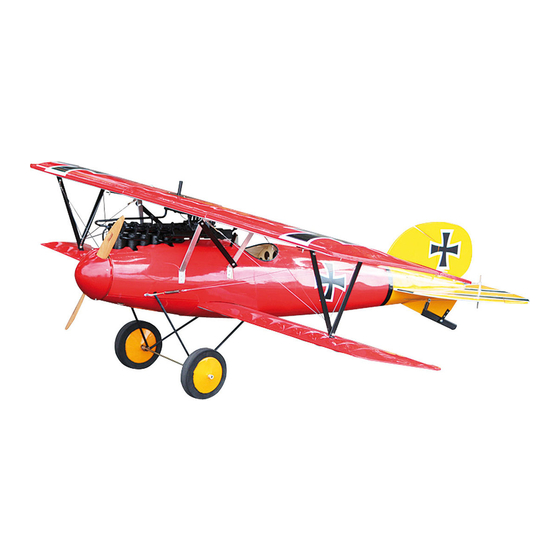
Shown with optional machine guns, Uranus 638109 motor and 18x8 wood propeller
ARF RC Albatros.
t
r
o
s
D
t
r
o
s
D
L
E
A
R
F
R
/
C
M
L
E
A
R
F
R
/
C
M
T
I
O
N
M
T
I
O
N
M
st
RC Albatros available in the RC world. This 1/5 sport scale
1
Page
of 18
.
V
a
.
V
a
O
D
E
L
A
I
R
P
L
A
N
O
D
E
L
A
I
R
P
L
A
N
A
N
U
A
A
N
U
A
E
E
L
L
#S140424
Advertisement
Table of Contents

Related Manuals for Maxford USA Albatros D.Va


Summary of Contents for Maxford USA Albatros D.Va
- Page 1 Kurt Wolff, and Karl Emil Schäfer credited the D.III as being both pleasant and easy to fly. The Albatros D.Va was the final development of the Albatros D.I family, and the last Albatros fighter to see operational service. The D.V entered service in May 1917 and, like the D.III before it, immediately began experiencing structural failures of the lower wing.
-
Page 2: Safety Precautions & Assembly Tips
4. Throughout the lifetime of this model, use only the Maxford USA-recommended power system and a new or well- maintained radio-control system. -
Page 3: Warranty, Liability Waiver & Return Policy
II. WARRANTY, LIABILITY WAIVER & RETURN POLICY Maxford USA guarantees this kit to be free from defects in material and workmanship at the time of purchase. All our products have been inspected in our factory and are checked again when shipped from our warehouse. However, Maxford USA cannot directly control the materials you may use or your final assembly process. -
Page 4: Specifications
ARF weight ............................... 9 pounds Flying weight ..........................14 to 15 pounds Power system ........0.90 to 1.20 2-stroke glow engine or Maxford USA U638109 motor with 100A HV ESC and 10S to 12S 3,000mAh or greater LiPo battery or equivalent Propeller ...... -
Page 5: Landing Gear
2 inner wheel collars to the axle. 6. Position both outer wheel collars so each wheel turns freely on its axle, then tighten the set screws to securely attach these 2 outer wheel collars to the axle. Copyright 2014 Maxford USA Page of 18 #S140424... -
Page 6: Tail Section
2. Use the guide holes to attach the lower radiator assembly to the bottom of the top wing‟s center section with four -inch (10mm) screws. Copyright 2014 Maxford USA Page of 18 #S140424... - Page 7 10. Attach the cabane struts to the fuselage with -inch (15mm) long wood screws as shown above. 9/16 11. Carefully remove and safely set aside the dummy engine and machine guns to avoid damage during the following assembly steps. Copyright 2014 Maxford USA Page of 18 #S140424...
- Page 8 5. Attach a 6-inch extension to each aileron servo. Bottom side of left (REMINDER: We recommend using optional Maxford USA wing panel is servo-extension safety clips to secure all servo extension and Y-cable connections.)
-
Page 9: Radio-Control System
4. As shown above, drill two -inch diameter holes at approx. 2 inches (5cm) from the end of the fuselage and 5/32 install elevator control horns behind where the elevator pull-pull cables exit the fuselage. Copyright 2014 Maxford USA Page of 18 #S140424... - Page 10 17. Pull the 2 pull-pull elevator cables that exit the top sides of the fuselage “snug” between the elevator servo‟s output arm and toward the control horns on the top sides of the elevator. Copyright 2014 Maxford USA Page of 18 #S140424...
-
Page 11: Power System
„more perfect fit.‟ The Maxford USA U638109 outer-rotor motor is a special design that is not only powerful, but is heavy enough to help achieve the correct CG for large WWI ARFs. A reasonable-sized motor such as this is much better than simply adding weight.) - Page 12 10. Use hook-and-loop material (not supplied) to secure your motor‟s battery in the compartment behind F-2. 11. With the Maxford USA 100A HV ESC you need to use a separate radio-system battery or UBEC (not included). We suggest you wait to position the radio-system‟s battery or UBEC until you check and/or adjust the CG.
-
Page 13: Glow Engine
(NOTE: A -inch open-ended wrench fits the propeller nut supplied with the Maxford USA U638109 motor.) 3. Test-fit the openings of the plastic dome-shaped front of the spinner around the propeller. Trim these openings if necessary. - Page 14 14. Drive a wood screw through the hole in each corner of the upper radiator and into the guide holes as shown below. Radiator’s vent tube Copyright 2014 Maxford USA Page of 18 #S140424...
- Page 15 B and C. (NOTE: If the cables are pulled unevenly or too tight, the wings may become warped – and warped wings might not be easily controllable in flight.) Spring, threaded rod and clevis Crimp tube NOTE: Illustrations are not drawn to scale Copyright 2014 Maxford USA Page of 18 #S140424...
- Page 16 Pull the cable snug between anchor points B and F, adjust the size of the wire loop, use pliers to crimp the tube securely onto the wire, snip off the excess wire with a pair of cutting pliers, and discard the excess. Copyright 2014 Maxford USA Page of 18...
-
Page 17: Setup And Adjustments
Congratulations! Assembly is finished! VII. SETUP & ADJUSTMENTS 1. Center of gravity (CG): For your initial flight we recommend your Albatros D.Va should balance when lifted at a point approx. 4 to 4 inches (100 to 110mm) behind the leading edge of the top wing. When correctly balanced, it will hang level, neither nose up nor nose down. -
Page 18: Storage, Field Setup & Preflight Checks
Transport and store your Albatros D.Va and its 2 sets of wing panels to await its next flight. e. Prepare for flight by reversing steps a through d, above.
Need help?
Do you have a question about the Albatros D.Va and is the answer not in the manual?
Questions and answers