Advertisement
Quick Links
C
C
U
U
SPORT-SCALE ARF R/C EP MODEL AIRPLANE
I N S T R U C T I O N M A N U A L
The Curtiss Model D was often called the Curtiss Pusher because practically all were built with their
propellers 'pushing' from behind their pilots. Much more importantly, since the Wright Brothers'
patents prevented Glenn Curtiss from using wing warping for lateral control, he designed his Model D
with ailerons, which turned out to be the far superior method for achieving lateral control. Early
examples of the Curtiss Pusher had an elevator at the front for pitch control with a horizontal stabilizer
at the rear. The front elevator was ultimately discovered to be unnecessary, resulting in the later
development of the Curtiss "Headless" Pusher.
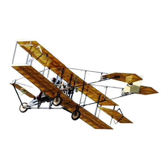
This sport-scale ARF R/C electric-powered Model D is based on the early-production "Headed"
Curtiss Pusher and is built to approx.
materials and comes prefinished with a two-color Mylar covering scheme.
Two flights of the Headed Curtiss Pusher formed the strong beginnings of a relationship between
Glenn Curtiss and the Navy that remained strong for decades: On November 14, 1910, test pilot
Eugene Ely took off from the USS Birmingham, which was the first time any aircraft successfully took
off and flew from a ship; then, on January 18, 1911, Eugene Ely performed the second precursor to
modern-day Navy aircraft-carrier air operations by landing a Model D aboard the USS Pennsylvania in
the first arrester-cable landing on a ship. In April 1911, the Navy purchased the Model D for use as an
airborne observation platform and the Aeronautical Division of the U.S. Army Signal Corps purchased
the Model D to use as a trainer. Consequently, the Curtiss Model D pusher became among the first
aircraft in the world to be built in any quantity.
We invite you to enjoy the pride of ownership and the joy of flying
this beautiful ARF sport-scale model of the famous Curtiss Pusher.
Copyright 2015 Maxford USA
R
T
I
S
S
R
T
I
S
scale. It is constructed from balsa, plywood and composite
1/9
P
P
U
S
S
U
S
Shown in flight with optional simulated pilot,
electric power system, receiver and servos.
Page 1
of 22 pages
H
E
R
H
E
R
#S150422
Advertisement

Subscribe to Our Youtube Channel
Related Manuals for Maxford USA Curtiss Pusher


Summary of Contents for Maxford USA Curtiss Pusher
- Page 1 Early examples of the Curtiss Pusher had an elevator at the front for pitch control with a horizontal stabilizer at the rear. The front elevator was ultimately discovered to be unnecessary, resulting in the later development of the Curtiss “Headless”...
- Page 2 4. Throughout the lifetime of this model, use only the Maxford USA-recommended power system and a new or well-maintained radio-control system.
- Page 3 Maxford USA from all current or future liability for any personal injury, property damage, or wrongful death, and if you (the buyer or user of this product) are involved in any claim or suit, you will not sue Maxford USA or any of its representatives.
- Page 4 3. Returned merchandise that is accepted by Maxford USA for credit is subject to a 10% to 20% restocking fee (the final amount will be determined by Maxford USA upon receipt and examination of the returned merchandise).
- Page 5 1 and 4. Learn about spoked at http://www.maxfordusa.com/vintagestyle3 spokedwheels.aspx.) Maxford USA 1/5 scale pilot figure. Servo extension safety clips. V. SPECIAL FEATURES Unique model of this historic pre-World War I aircraft.
- Page 6 8. Tighten all the 2mm dia. bolts into the nuts on both tail boom assemblies. Page 6 Copyright 2015 Maxford USA of 22 pages #S150422...
- Page 7 As shown at the right, the head of the front elevator’s hinge-bolt at the front end of each boom faces outward; the threaded ends of these bolts face each other.) Page 7 Copyright 2015 Maxford USA of 22 pages #S150422...
- Page 8 (NOTE: As shown at the left and on the next page, position the upper nose-wheel struts to of the vertical OUTSIDE REAR engine-mounting struts and to of the vertical INSIDE FRONT engine-mounting struts.) Page 8 Copyright 2015 Maxford USA of 22 pages #S150422...
- Page 9 Position the elevator’s metal joiner and attach the rudder’s hinge assembly to the center of the horizontal stabilizer with 2mm bolts and nuts as pictured at the top of the following page. Page 9 Copyright 2015 Maxford USA of 22 pages #S150422...
- Page 10 Holding the elevator ‘level’ (at the same angle as the horizontal stabilizer), snug the EZ-Link connector onto the elevator pushrod. Set both elevators to the same angle (neither 'up' nor 'down') as the horizontal stabilizer. Page 10 Copyright 2015 Maxford USA of 22 pages #S150422...
- Page 11 As pictured at the right, secure the extensions to the bottom of the lower wing’s center section with transparent tape. Page 11 Copyright 2015 Maxford USA of 22 pages #S150422...
- Page 12 Page 12 Copyright 2015 Maxford USA of 22 pages #S150422...
- Page 13 EZ-Link connector to an approx. -inch long servo arm NOTE: The photos on this page show supplied with your the 'standard' wheels for this ARF. servo. Page 13 Copyright 2015 Maxford USA of 22 pages #S150422...
- Page 14 Reverse either 2 of the 3 motor wires if your motor runs in the wrong direction. Page 14 Copyright 2015 Maxford USA of 22 pages #S150422...
- Page 15 45. Attach a 10-inch servo extension to each aileron servo. (NOTE: Help ensure the security of all servo connections by installing optional Maxford USA servo-extension safety clips.) 46. Guide the aileron servo extensions and servo leads into the servo bays, through the wing panels, and out through the root ribs of the upper wing panels.
- Page 16 (Do not apply glue at this time.) Outer-rear strut Inner-rear strut Preinstalled bolts and nuts at the middle of the rear struts. Page 16 Copyright 2015 Maxford USA of 22 pages #S150422...
- Page 17 65. Tighten the aileron pushrod-clamping bolt in each EZ-Link connector onto its pushrod. Once the ailerons have been adjusted, apply thin CA or threadlock compound to secure the clamping bolts. Page 17 Copyright 2015 Maxford USA of 22 pages #S150422...
- Page 18 If you choose to install the supplied string to simulate wing wires, guide the string between anchor points A through L and 1 through 4 pictured at the top of the following page. Page 18 Copyright 2015 Maxford USA of 22 pages #S150422...
- Page 19 Repeat the above process to install wires between the left pair of outer wing panels. Install wires between the center sections as shown below. Install wires between the swivels at the outside surfaces of the tail booms as shown below. Page 19 Copyright 2015 Maxford USA of 22 pages #S150422...
- Page 20 CA adhesive or Maxford USA servo-extension safety clips. 71. If you install an optional Maxford USA pilot figure, use hook-and-loop material or epoxy to attach the pilot figure to scrap wood and glue the wood across the arms of the pilot’s seat as pictured below.
- Page 21 5. Ensure the propeller is securely attached to your motor and remains undamaged and correctly balanced. 6. As with all radio-controlled model airplanes, your Curtiss Pusher must pass the radio-range ground check recommended by your radio’s manufacturer or you may not fly safely.
- Page 22 Any testing, flying and use of this model airplane is done entirely at your own risk. PLEASE ENJOY YOUR HOBBY AND FLY SAFELY! Manufactured by: Maxford USA RC Model Mfg, Inc. Distributed by: Maxford USA RC Model Distribution, Inc.
Need help?
Do you have a question about the Curtiss Pusher and is the answer not in the manual?
Questions and answers