Table of Contents
Advertisement
SPLIT-TYPE, HEAT PUMP AIR CONDITIONERS
TECHNICAL & SERVICE MANUAL
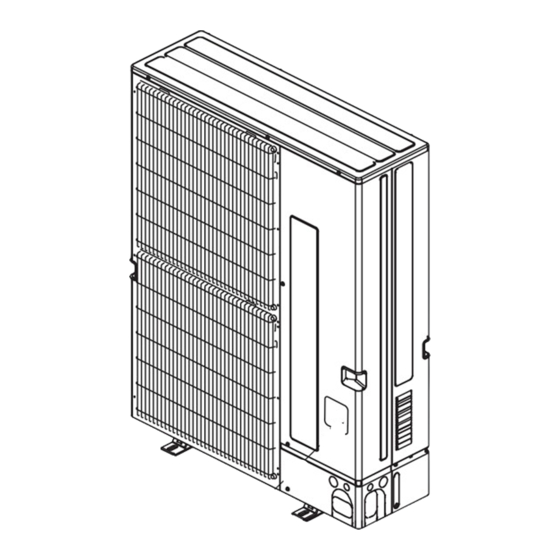
Outdoor unit
[Model Name]
[Service Ref.]
PUMY-P60NKMU
PUMY-P60NKMU
PUMY-P60NKMU-BS
PUMY-P60NKMU-BS
Model name
indication
OUTDOOR UNIT
CONTENTS
1. SAFETY PRECAUTION ................................... 2
2. OVERVIEW OF UNITS ..................................... 5
3. SPECIFICATIONS .......................................... 10
4. DATA ................................................................ 11
5. OUTLINES AND DIMENSIONS ..................... 17
6. WIRING DIAGRAM ......................................... 18
8. TROUBLESHOOTING .................................... 29
9. ELECTRICAL WIRING ................................. 100
10. REFRIGERANT PIPING TASKS .................. 103
11. DISASSEMBLY PROCEDURE ..................... 109
PARTS CATALOG (OCB502)
HFC
utilized
R410A
November 2013
No. OCH502
REVISED EDITION-C
Revision:
• Replaced troubleshooting
table with flow chart in
REVISED EDITION-C.
• Some descriptions have
been modified.
• Please void OCH502
REVISED EDITION-B.
Note :
• This service manual
describes technical data
of outdoor unit. As for
indoor units, refer to its
service manual.
Advertisement
Table of Contents

Related Manuals for Mitsubishi PUMY-P60NKMU


Summary of Contents for Mitsubishi PUMY-P60NKMU
- Page 1 November 2013 No. OCH502 REVISED EDITION-C TECHNICAL & SERVICE MANUAL Outdoor unit Revision: [Model Name] [Service Ref.] • Replaced troubleshooting PUMY-P60NKMU table with flow chart in REVISED EDITION-C. PUMY-P60NKMU • Some descriptions have been modified. PUMY-P60NKMU-BS PUMY-P60NKMU-BS • Please void OCH502 REVISED EDITION-B.
-
Page 2: Safety Precaution
SAFETY PRECAUTION CAUTIONS RELATED TO NEW REFRIGERANT Cautions for units utilizing refrigerant R410A Use a vacuum pump with a reverse flow check Use new refrigerant pipes. valve. Avoid using thin pipes. Vacuum pump oil may flow back into refrigerant cycle and that can cause deterioration of refrigerant oil etc. - Page 3 [1] Cautions for service (1) Perform service after recovering the refrigerant left in unit completely. (2) Do not release refrigerant in the air. (3) After completing service, charge the cycle with specified amount of refrigerant. (4) When performing service, install a filter drier simultaneously. Be sure to use a filter drier for new refrigerant.
- Page 4 Cautions for refrigerant piping work New refrigerant R410A is adopted for replacement inverter series. Although the refrigerant piping work for R410A is same as for R22, exclusive tools are necessary so as not to mix with different kind of refrigerant. Furthermore as the working pressure of R410A is 1.6 times higher than that of R22, their sizes of flared sections and flare nuts are different.
-
Page 5: Overview Of Units
OVERVIEW OF UNITS 2-1. Auxiliary HEATING ON/OFF CONTROL SET-UP (1) Auxiliary heating operation controls another heat source that depends on the main system's operations, which means the interlock operation shown in "b)" will be possible. Indoor unit must be R410A UL model for this function to operate. b) Different Indoor unit applications that can be applied: (2) Outdoor unit DIPSW5-4 for auxiliary heating control: Set DIPSW5-4 when power is turned off at unit. - Page 6 (4) Determine fan airflow setting during indoor thermo-OFF conditions: a) These settings are done within Indoor DIPSW1-7 and DIPSW1-8, see chart below for options. b) Recommended SW1-7 OFF and SW1-8 ON will determine airflow based on "Setting on the remote controller". Auxiliary heating Fan speed Fan speed...
- Page 7 (6) Locally procured wiring A basic connection method is shown. (i.e. interlocked operation with the electric heater with the fan speed setting on high) Indoor unit Outdoor unit Remote control Board Relay circuit Adapter control board control board Dip switch SW5-4 "ON"...
- Page 8 2-2. UNIT CONSTRUCTION Outdoor unit Type 06 ~ Type 72 Capacity Indoor unit that 1~ 12 unit Number of units can be connected 50% ~130% of outdoor unit capacity Total system wide capacity CMY-Y62-G-E CMY-Y64-G-E CMY-Y68-G-E Branching pipe Branch header Branch header Branch header components...
-
Page 9: Unit Specifications
2-3. UNIT SPECIFICATIONS (1) Method for identifying MULTI-S model ■ ■ Indoor unit < When using Model 30 > Outdoor unit <When using model 60 > P L F Y - P 30 N B M U - E PU M Y - P 60 N K M U -BS UL model Outdoor unit Refrigerant... -
Page 10: Specifications
SPECIFICATIONS Service Ref. Item PUMY-P60NKMU(-BS) Cooling Capacity Btu/h 60,000 Heating Capacity Btu/h 66,000 Input ( Cool ) 4.80 Input Current ( Cool ) 21.5 Power factor (Cool) 97.0 Input ( Heat ) 6.15 Input Current ( Heat ) 27.6 Power factor (Heat) 97.0... -
Page 11: Data
(2) Sample calculation System assembled from indoor and outdoor unit (in this example the total capacity of the indoor units is greater than that of the outdoor unit) • Outdoor unit PUMY-P60NKMU PKFY-P08NAMU-E o 2 , PLFY-P18NBMU-E o 3 • Indoor unit According to the conditions in 1, the total capacity of the indoor unit will be: 8 o 2 + 18 o 3 = 70 The following figures are obtained from the 52 total capacity row of the standard capacity table (4-2.):... - Page 12 4-2. STANDARD OPERATION DATA (REFERENCE DATA) Outdoor unit model Operation PUMY-P60NKMU(-BS) Indoor 26.7°C/19.4°C [80°F/67°F] 21.1°C/— [70°F/—] Ambient DB/WB temperature Outdoor 35°C/— [95°F/—] 8.3°C/6.1°C [47°F/43°F] No. of connected units Unit Indoor unit No. of units in operation Model — 06×2/24×2 Operating...
- Page 13 4-3. STANDARD CAPACITY DIAGRAM PUMY-P60NKMU PUMY-P60NKMU-BS Capacity Power consumption EER / COP Current (A) / 230V Current (A) / 208V Total capacity (Btu/h) (kW) of indoor units Cooling Heating Cooling Heating Cooling Heating Cooling Heating Cooling Heating 6000 7000 0.71 1.06...
- Page 14 4-4. CORRECTING COOLING AND HEATING CAPACITY 4-4-1. Correcting changes in air conditions (1) The performance curve charts (Figure 1, 2) show the ratio by the temperature condition change when the rated capacity (total capacity) and the rated input are presumed 1, under standard length (7.6 m [25 ft]) and standard temperature condition. •...
- Page 15 Figure 3 High heating performance curve :DB (°FDB) Ratio of heating capacity 15 (59) 21.1 (70) 25 (77) 27.2 (81) INDOOR Ratio of power input :DB (°FDB) 15 (59) 21.1 (70) 25 (77) 27.2 (81) INDOOR [°CWB] [°FWB] OUTDOOR 4-4-2. Correcting capacity for changes in the length of refrigerant piping (1) During cooling, obtain the ratio (and the equivalent piping length) of the outdoor units rated capacity and the total in-use indoor capacity, and find the capacity ratio corresponding to the standard piping length from Figure 3.
-
Page 16: Noise Criterion Curves
Correction factor diagram Outdoor Intake temperature (W.B.°F) Outdoor Intake temperature (W.B.°C) 0.98 0.89 0.88 0.89 0.95 0.95 0.95 Correction factor 4-5. NOISE CRITERION CURVES PUMY-P60NKMU SPL(dB) MODE LINE COOLING PUMY-P60NKMU-BS HEATING NC-70 MICROPHONE 1m [3.3 ft] UNIT NC-60 NC-50 1.5m... -
Page 17: Outlines And Dimensions
OUTLINES AND DIMENSIONS PUMY-P60NKMU Unit : mm <inch> PUMY-P60NKMU-BS OCH502C... -
Page 18: Wiring Diagram
WIRING DIAGRAM LEV-A LEV-B PUMY-P60NKMU 63LS 63HS TH7 TH6 TH3 TH4 TH2 The black square ( ) indicates a switch position. t° t° t° t° t° PUMY-P60NKMU-BS MULTI.B. CN3D CN3S CN3N SWU2 SWU1 CNF1 1 2 1 2 1 2... -
Page 19: Necessary Conditions For System Construction
NECESSARY CONDITIONS FOR SYSTEM CONSTRUCTION 7-1. TRANSMISSION SYSTEM SETUP OCH502C... -
Page 20: Refrigerant System Diagram
7-2. REFRIGERANT SYSTEM DIAGRAM PUMY-P60NKMU PUMY-P60NKMU-BS Unit: mm <inch> Service Check valve Thermistor (TH7) port (High pressure) Ball valve (Outdoor temperature) 4-way valve Refrigerant Gas pipe Solenoid Strainer <3/4> valve (SV1) Oil separator High pressure Check valve Strainer sensor (63HS) -
Page 21: System Control
7-3. SYSTEM CONTROL Example for the System • Example for wiring control cables, wiring method and address setting, permissible lengths, and the prohibited items are listed in the standard system with detailed explanation. The explanation for the system in this section : Use 1 single outdoor unit and multiple outdoor units for M-NET remote control system. - Page 22 • Name, Symbol and the Maximum Remote controller Units for Connection Name Symbol Maximum units for connection Outdoor unit — Indoor unit 1 OC unit can be connected to 1-12 IC units M-NET remote Maximum 2 RC for 1 indoor unit, Maximum 12 RC for 1 OC controller Permissible Lengths Prohibited items...
- Page 23 B. Example of a group operation system with 2 or more outdoor units and a M-NET remote controller. (Address settings are necessary.) (51) (01) (02) (05) (06) M1 M2 S M1 M2 S M1 M2 S M1 M2 S M1 M2 S M1 M2 S (105) (155)
- Page 24 • Name, Symbol, and the Maximum Units for Connection • Longest length via outdoor units : L [ 500 meters [1450 ft] (1.25 mm² [AWG16]) • Longest transmission cable length : L [ 200 meters [656 ft] (1.25 mm² [AWG16]) •...
- Page 25 C. Example of a MA remote controller system (address setting is not necessary.) NOTE : In the case of same group operation, need to set the address that is only main indoor unit. Example of wiring control cables Wiring Method and Address Setting 1.
- Page 26 Permissible Lengths Prohibited items The MA remote controller and the Longest transmission cable length M-NET remote controller cannot be [ 200 m [656 ft] (1.25 mm² used together with the indoor unit [AWG16]) of the same group. MA remote controller cable length [ 200 m [656 ft] (0.3 ~ 1.25 mm²...
- Page 27 D. Example of a group operation with 2 or more outdoor units and a MA remote controller. (Address settings are necessary.) (51) (01) (02) (05) (06) TB15 TB15 TB15 TB15 M1 M2 S M1 M2 S M1 M2 S M1 M2 S M1 M2 S M1 M2 S (53)
- Page 28 • Name, Symbol, and the Maximum Units for Connection Longest length via outdoor unit (M-NET cable): [ 500 m [1640 ft] (1.25 e [AWG16] or more) and L Longest transmission cable length (M-NET cable): [ 200 m [656 ft] (1.25 e [AWG16] or more) and L and L and L...
-
Page 29: Troubleshooting
TROUBLESHOOTING 8-1. CHECK POINTS FOR TEST RUN 8-1-1. Procedures of test run (1) Before a test run, make sure that the following work is completed. • Installation related : Make sure that the panel of cassette type and electrical wiring are done. Otherwise electrical functions like auto vane will not operate normally. - Page 30 8-1-2. Special Function Operation and Settings (for M-NET Remote Controller) • It is necessary to perform “group settings” and “paired settings” at making group settings of different refrigerant systems (multiple outdoor unit). (A) Group settings: Enter the indoor unit controlled by the remote controller, check the content of entries, and clear entries, etc.
- Page 31 (2) Address check: Refer to section (1) regarding address entry. a) In making group settings: • Turn off the remote controller: Press the remote controller's ON/OFF button to stop operation (the indicator light will go off). • Locate the indoor unit address display mode: Press the FILTER and k buttons on the remote controller simultaneously and hold for 2 seconds.
- Page 32 8-1-3. Countermeasures for Error During Test Run • If a problem occurs during test run, a code number will appear in the temperature display area on the remote controller (or LED on the outdoor unit), and the air conditioning system will automatically cease operating. Determine the nature of the abnormality and apply corrective measures.
- Page 33 Check code Serial commucication error 0403 Abnormal points and detection methods Causes and check points Abnormal if serial communication between the outdoor controller board Wire breakage or contact failure of connector CN2 or and outdoor power board is defective. Malfunction of power board communication circuit on outdoor controller board Malfunction of communication circuit on outdoor power board...
- Page 34 Check code Compressor temperature trouble 1102 Chart 1 of 2 Abnormal points and detection methods Causes and check points (1) Abnormal if TH4 falls into following temperature conditions; Malfunction of stop valve Over-heated compressor operation caused by ●exceeds 110 [230 °F]continuously for 5 minutes shortage of refrigerant ●exceeds 125 [257 °F]...
- Page 35 Check code Compressor temperature trouble 1102 Chart 2 of 2 ●Diagnosis of defectives Make sure to turn the power OFF before connecting/disconnecting any connectors, or replacing boards. Diagnosis Remedy Continued from the previous page Disconnect the thermistor wiring to check the resistance.
- Page 36 Check code Low pressure trouble 1300 Chart 1 of 3 Abnormal points and detection methods Causes and check points <63L equipped model (63LS non-equipped)> Defective operation of stop valve (not fully open) (1) Low pressure (63L is in operation) Clogged or broken pipe. Abnormal if 63L operates (under-0.03MPa) during compressor Malfunction or locked outdoor fan motor operation.
- Page 37 Check code Low pressure trouble 1300 Chart 2 of 3 ●Diagnosis of defectives Make sure to turn the power OFF before connecting/disconnecting any connectors, or replacing boards. Diagnosis Remedy Continued from the previous page Is there dirt on the indoor heat Wash the indoor heat exchanger.
- Page 38 Check code Low pressure trouble 1300 Chart 3 of 3 ●Diagnosis of defectives Make sure to turn the power OFF before connecting/disconnecting any connectors, or replacing boards. Diagnosis Remedy Continued from the previous page Check the resistance of SV1. Is there a resistance detected? Replace the SV1.
- Page 39 Check code High pressure trouble 1302 Chart 1 of 4 Abnormal points and detection methods Causes and check points <63H equipped model (63HS non-equipped)> Defective operation of stop valve (not fully open) (1) High pressure abnormality (63H operation) Clogged or broken pipe. Abnormal if 63H operates(*) during compressor operation.
- Page 40 Check code High pressure trouble 1302 Chart 2 of 4 ●Diagnosis of defectives Make sure to turn the power OFF before connecting/disconnecting any connectors, or replacing boards. Diagnosis Remedy Continued from the previous page Is the indoor unit fi lter clogged? Clean the fi...
- Page 41 Check code High pressure trouble 1302 Chart 3 of 4 ●Diagnosis of defectives Make sure to turn the power OFF before connecting/disconnecting any connectors, or replacing boards. Diagnosis Remedy Continued from the previous page Is there a resistance detected? Replace the TH7. Disconnect the indoor LEV wiring to check the resistance.
- Page 42 Check code High pressure trouble 1302 Chart 4 of 4 ●Diagnosis of defectives Make sure to turn the power OFF before connecting/disconnecting any connectors, or replacing boards. Diagnosis Remedy Continued from the previous page Is there a resistance detected? Replace the SV1. <63H equipped model (63HS non-equipped)>...
- Page 43 Check code Superheat due to low discharge temperature trouble 1500 Chart 1 of 2 Abnormal points and detection methods Causes and check points Abnormal if the discharge superheat is continuously detected less than Disconnection or loose connection of TH4 or equal to −15 [5 °F]* for 5 minutes even though the indoor LEV has Defective holder of TH4 minimum open pulse after the compressor starts operating for 10 minutes.
- Page 44 Check code Superheat due to low discharge temperature trouble 1500 Chart 2 of 2 ●Diagnosis of defectives Make sure to turn the power OFF before connecting/disconnecting any connectors, or replacing boards. Diagnosis Remedy Continued from the previous page Is there a resistance detected? Replace the indoor LEV.
- Page 45 Check code Refrigerant shortage trouble 1501 Chart 1 of 2 Abnormal points and detection methods Causes and check points (1) Abnormal when all of the following conditions are satisfi ed: Defective operation of stop valve (not fully open) 1. The compressor is operating in HEAT mode Defective thermistor 2.Discharge super heat is 80 [176 °F] or more.
- Page 46 Check code Refrigerant shortage trouble 1501 Chart 2 of 2 ●Diagnosis of defectives Make sure to turn the power OFF before connecting/disconnecting any connectors, or replacing boards. Diagnosis Remedy Continued from the previous page Is there a resistance detected? Replace the thermistor. Check the 63HS voltage.
-
Page 47: Blocked Valve In Cooling Mode
Check code Blocked valve in cooling mode 1501 Abnormal points and detection methods Causes and check points Abnormal if stop valve is blocked during cooling operation. Outdoor liquid/gas valve is blocked. Mulfunction of outdoor LEV (LEV1)(blockage) Abnormal when both of the follwing temperature condition is satisfi ed for 20 minutes or more during coling condition. -
Page 48: Way Valve Trouble In Heating Mode
Check code 4-way valve trouble in heating mode 1508 Abnormal points and detection methods Causes and check points Abnormal if 4-way valve does not operate during heating operation. 4-way valve failue Disconnection or failure of 4-way valve coil Abnormal when any of the following temperature condition is satisfi ed for 3 Clogged drain pipe min. - Page 49 Check code Compressor current interruption (Locked compressor) 4100 Chart 1 of 2 Abnormal points and detection methods Causes and check points Abnormal if overcurrent of DC bus or compressor is detected 30 seconds Closed stop valve after the compressor starts operating. Decrease of power supply voltage Looseness, disconnection or converse of compressor wiring connection...
- Page 50 Check code Compressor current interruption (Locked compressor) 4100 Chart 2 of 2 ●Diagnosis of defectives Make sure to turn the power OFF before connecting/disconnecting any connectors, or replacing boards. Diagnosis Remedy Continued from the previous page Set the model selection switch correctly, Are they set properly? then restart.
- Page 51 Check code Compressor overcurrent interruption 4210 Chart 1 of 2 Abnormal points and detection methods Causes and check points Abnormal if overcurrent of DC or the compressor is detected within 30 Closed outdoor stop valve seconds after the compressor starts operating. Decrease of power supply voltage Looseness, disconnection or reverse phase of compressor wiring connection...
- Page 52 Check code Compressor overcurrent interruption 4210 Chart 2 of 2 ●Diagnosis of defectives Make sure to turn the power OFF before connecting/disconnecting any connectors, or replacing boards. Diagnosis Remedy Continued from the previous page Connect the compressor wiring (U, V and W phase) properly, then turn the power Are they connected properly? back ON.
- Page 53 Check code Voltage shortage/Overvoltage/PAM error/T open-phase/ 4220 Power synchronization signal error Chart 1 of 2 Abnormal points and detection methods Causes and check points Abnormal if any of following symptoms are detected; Decrease/increase of power supply voltage, or T open-phase ●Decrease of DC bus voltage to 200V Disconnection of compressor wiring ●Increase of DC bus voltage to 400V...
- Page 54 Check code Voltage shortage/Overvoltage/PAM error/T open-phase/ 4220 Power synchronization signal error Chart 2 of 2 ●Diagnosis of defectives Make sure to turn the power OFF before connecting/disconnecting any connectors, or replacing boards. The black square (■) indicates a switch position. Diagnosis Remedy Continued from the previous page...
- Page 55 Check code Heatsink temperature trouble 4230 Abnormal points and detection methods Causes and check points Abnormal if TH8 detects a temperature outside the specifi ed range during Blocked outdoor fan compressor operation. Malfunction of outdoor fan motor Blocked airfl ow path TH8: Heatsink temperature thermistor Rise of ambient temperature Characteristic defect of thermistor...
- Page 56 Check code Power module trouble 4250 Abnormal points and detection methods Causes and check points Abnormal if overcurrent of DC bus or compressor is detected 30seconds Closed outdoor stop valve after the compressor starts operating. To determine the source of Decrease of power supply voltage abnormality, either the compressor or the power module, drive the power Disconnection, looseness or conversed connection...
- Page 57 Check code Rotational frequency of outdoor fan motor trouble 4400 Abnormal points and detection methods Causes and check points Abnormal if no rotational frequency is detected, or detected a value Malfunction of fan motor outside the specifi ed range during fan motor operation. Disconnection of CNF connector Defective outdoor controller board ●Diagnosis of defectives...
- Page 58 Check code Compressor temperature thermistor (TH4) open/short 5101 Abnormal points and detection methods Causes and check points Abnormal if TH4 detects to be open/short. Disconnection or contact failure of connectors (The open/short detection is disabled for 10 minutes after compressor Characteristic defect of thermistor starts, during defrosting operation, or for 10 minutes after returning from Defective outdoor controller board...
- Page 59 Check code Low-pressure saturated temperature thermistor (TH6) open/short 5102 Abnormal points and detection methods Causes and check points Abnormal if TH6 detects to be open/short. Disconnection or contact failure of connectors (The open/short detection is disabled during 10 sec. to 10 min. after Characteristic defect of thermistor compressor starts, during defrosting operation, or for 10 min.
- Page 60 Check code Piping temperature thermistor (TH3) open/short 5105 Abnormal points and detection methods Causes and check points Abnormal if TH3 detects to be open/short. Disconnection or contact failure of connectors (The open/short detection is disabled during 10 sec. to 10 min. after Characteristic defect of thermistor compressor starts, during defrosting operation, or for 10 min.
- Page 61 Check code Outdoor temperature thermistor (TH7) open/short 5106 Abnormal points and detection methods Causes and check points Abnormal if TH7 detects to be open/short Disconnection or contact failure of connectors Open: -40 [-40°F] or less Characteristic defect of thermistor Short: 90 [194°F] or more TH7: Outdoor temperature thermistor Defective outdoor controller board ●Diagnosis of defectives...
- Page 62 Check code HIC piping temperature thermistor (TH2) open/short 5109 Abnormal points and detection methods Causes and check points Abnormal if TH2 detects to be open/short. Disconnection or contact failure of connectors Open: -40 [-40°F] or less Characteristic defect of thermistor Short: 90 [194°F] or more TH2: HIC piping temperature thermistor Defective outdoor controller board...
- Page 63 Check code Heatsink temperature thermistor(TH8) open/short 5110 Abnormal points and detection methods Causes and check points Abnormal if TH8 detects to be open/short. Disconnection or contact failure of connectors P36/48 model Characteristic defect of thermistor Open: -102 [215.6°F] or less Defective outdoor controller board Short: 34.8 [-30.6°F] or more P60 model...
- Page 64 Check code High-pressure sensor (63HS) trouble 5201 Abnormal points and detection methods Causes and check points When the detected pressure in the high-pressure sensor is 1kgf/F or Defective high-pressure sensor less during operation, the compressor stops operation and enters into Decrease of internal pressure caused by gas an anti-restart mode for 3 minutes.
- Page 65 Check code Low-pressure sensor (63LS) trouble 5202 Abnormal points and detection methods Causes and check points When the detected pressure in the low-pressure sensor is -2.3kgf/F Defective low-pressure sensor or less, or 23.1kgf/F or more during operation, the compressor stops Decrease of internal pressure caused by gas operation with a check code <5202>.
- Page 66 Check code Primary current error 5300 Abnormal points and detection methods Causes and check points Abnormal if the detected current sensor input value (primary current) Decrease/ trouble of power supply voltage during compressor operation is outside the specifi ed range. Disconnection of compressor wiring Input sensor trouble on outdoor power board ●Diagnosis of defectives...
-
Page 67: Duplex Address Error
Check code Duplex address error 6600 Abnormal points and detection methods Causes and check points Abnormal if 2 or more units with the same address are exsisting. There are 2 units or more with the same address in their controller among outdoor unit, indoor unit, Fresh Master, Lossnay or remote controller Noise interference on indoor/outdoor connectors ●Diagnosis of defectives... - Page 68 Check code Transmission processor H/W error 6602 Abnormal points and detection methods Causes and check points Abnormal if the transmission line shows "1" although the transmission A transmitting data collision occurred because of a processor transmitted "0". wiring work or polarity change has performed while the power is ON on either of the indoor/outdoor unit, Fresh Master or Lossnay Malfunction of transmitting circuit on transmission...
-
Page 69: Transmission Bus Busy Error
Check code Transmission bus BUSY error 6603 Abnormal points and detection methods Causes and check points Over error by collision The transmission processor is unable to transmit due Abnormal if no-transmission status caused by a transmitting data to a short-cycle voltage such as noise is mixed on collision is consecutive for 8 to 10minutes. -
Page 70: Signal Communication Error With Transmission Processor
Check code Signal communication error with transmission processor 6606 Abnormal points and detection methods Causes and check points Abnormal if the data of unit/transmission processor were not normally Accidental disturbance such as noise or lightning transmitted. surge Hardware malfunction of transmission processor Abnormal if the address transmission from the unit processor was not normally transmitted. - Page 71 Check code No ACK error 6607 Chart 1 of 4 Abnormal points and detection methods Causes and check points Represents a common error detection The previous address unit does not exist since An abnormality detected by the sending side controller when receiving the address switch was changed while in electric no ACK from the receiving side, though signal was once sent.The continuity status.
- Page 72 Check code No ACK error 6607 Chart 2 of 4 Abnormal points and detection methods Causes and check points While the indoor unit is operating with multi refrigerant system Fresh Master, an abnormality The cause of displayed address and attribute is on the Fresh Master is detected when the indoor unit transmits signal side to the remote controller while the outdoor unit with...
- Page 73 Check code No ACK error 6607 Chart 3 of 4 ●Diagnosis of defectives Make sure to turn the power OFF before connecting/disconnecting any connectors, or replacing boards. Diagnosis Remedy Procedure 1: Turn the power OFF of indoor/outdoor unit, Fresh Master, Lossnay and remote controller simultaneously for 2 minutes or more, then turn the power back ON.
- Page 74 Check code No ACK error 6607 Chart 4 of 4 ●Diagnosis of defectives Make sure to turn the power OFF before connecting/disconnecting any connectors, or replacing boards. Diagnosis Remedy Continued from the previous page Apply the correct kind of transmission line, Is the correct kind of transmission then perform the procedure 1.
-
Page 75: No Response Frame Error
Check code No response frame error 6608 Abnormal points and detection methods Causes and check points Abnormal if receiving no response command while already received ACK. Continuous failure of transmission due to noise etc The sending side searches the error in 30 seconds interval for 6 times Decline of transmission voltage/signal caused by continuously. -
Page 76: Total Capacity Error
Check code Total capacity error 7100 Abnormal points and detection methods Causes and check points When the total of the number on connected indoor unit model names The total of number on connected indoor unit model exceeds the specifi ed capacity level (130% of the number on the outdoor names exceeds the specifi... -
Page 77: Capacity Code Error
Check code Capacity code error 7101 Abnormal points and detection methods Causes and check points When a connected indoor unit is incompatible, a check code <7101> is The model name of connected indoor unit (model code) displayed. is read as incompatible. The connectable indoor units are: ·P36/P48 model: P6 to P54 model (code3 to 28) ·P60 model: P15 to P140 model (code 4 to 28) - Page 78 Check code Connecting excessive number of units 7102 Abnormal points and detection methods Causes and check points When the connected AC unit exceeds the limit, a check code <7102> is Connecting more AC units than the limit displayed. Abnormal if connecting status does not comply with the following limit;...
-
Page 79: Address Setting Error
Check code Address setting error 7105 Abnormal points and detection methods Causes and check points The address setting of outdoor unit is wrong. Wrongly set address of indoor unit The outdoor unit is not set in 000, or in the range of 51 to 100. -
Page 80: Remote Controller Diagnosis
8-2. REMOTE CONTROLLER DIAGNOSIS · MA remote controller is equipped with the diagnosis function If the air conditioner cannot be operated from the remote controller, diagnose the remote controller as explained below. First, check that the power-on indicator is lit. If the correct voltage (DC12 V) is not supplied to the remote controller, the indicator will not light. - Page 81 8-3. REMOTE CONTROLLER TROUBLE CENTRALLY CONTROLLED 1Hr. ON OFF °C CLOCK CHECK FILTER CHECK MODE °C TEST RUN STAND BY ERROR CODE “ ” Indicator: appears when current is carried. NOT AVAILABLE FUNCTION DEFROST TEMP. ON/OFF FILTER CHECK TEST TIMER SET (M-NET Remote controller) (1) For M-NET remote controller systems Symptom or inspection code...
- Page 82 8-4. THE FOLLOWING SYMPTOM DO NOT REPRESENT TROUBLE (EMERGENCY) Display of remote controller CAUSE Symptom Even the cooling (heating) The indoor unit can not cool (Heat) if other indoor units are heating "Cooling (Heating)" blinks operation selection button (Cooling). is pressed, the indoor unit cannot be operated.
- Page 83 8-5. INTERNAL SWITCH FUNCTION TABLE PUMY-P60NKMU PUMY-P60NKMU-BS ■ The black square ( ) indicates a switch position. Operation in each switch setting Switch Step Function Remarks When to set <Initial settings> SWU1 1s digit Before turning the power on SWU2...
- Page 84 ■ The black square ( ) indicates a switch position. Operation in each switch setting Switch Step Function Remarks When to Set — — — — Switch of current limitation <Initial settings> Before turning the Enable Normal reading in a different way power on.
- Page 85 8-6. OUTDOOR UNIT INPUT/OUTPUT CONNECTOR State (CN51) Distant control board Lamp power supply Relay circuit Procure locally External output adapter (PAC-SA88HA-E) Max. 10m CN51 Outdoor unit control board : Error display lamp : Compressor operation lamp X, Y: Relay (Coil standard of 0.9W or less for DC 12V) X, Y: Relay (DC1mA) Auto change over (CN3N) Remote control panel...
- Page 86 8-7. HOW TO CHECK THE PARTS PUMY-P60NKMU PUMY-P60NKMU-BS Parts name Check points Thermistor (TH2) Disconnect the connector then measure the resistance with a tester. <HIC piping temp.> (At the ambient temperature 10:~30:) Thermistor (TH3) Normal Abnormal <Piping temp.> 160k"~410k" Thermistor (TH4) <Compressor>...
- Page 87 Check method of fan motor (fan motor/outdoor controller board) Notes · High voltage is applied to the connecter (CNF1, 2) for the fan motor. Pay attention to the service. · Do not pull out the connector (CNF1, 2) for the motor with the power supply on. (It causes trouble of the outdoor controller board and fan motor.) Self check...
- Page 88 8-8. HOW TO CHECK THE COMPONENTS <Thermistor feature chart> Low temperature thermistors • Thermistor <HIC pipe> (TH2) • Thermistor <Outdoor pipe> (TH3) • Thermistor <Low pressure saturated temperature> (TH6) • Thermistor <Outdoor> (TH7) Thermistor R0 = 15k' ± 3% B constant = 3480 ± 2% =15exp{3480( –...
- Page 89 8-9. TEST POINT DIAGRAM Outdoor controller board PUMY-P60NKMU PUMY-P60NKMU-BS <CAUTION> TEST POINT is high voltage. CN51 CN102 External signal Connect to the M-P.B Model select Pump down Test run Forced defrost Model select output (Transmission power board) CN40,CN41 Function switch...
- Page 90 Outdoor power board Brief check of POWER MODULE * Usually, each point is in a state of being short-circuited if they are broken. PUMY-P60NKMU Measure the resistance in the following points (connectors, etc.). PUMY-P60NKMU-BS If they are short-circuited, it means that they are broken.
- Page 91 Transmission power board PUMY-P60NKMU PUMY-P60NKMU-BS Connect to the outdoor multi controller board 1-2: 24–30V DC 3-4: 24–30V DC Connect to the outdoor noise filter circuit board 1–3 : 208/230V AC OCH502C...
- Page 92 SW:setting 0..OFF 8-10. OUTDOOR UNIT FUNCTIONS 1..ON OCH502C...
- Page 93 OCH502C...
- Page 94 OCH502C...
- Page 95 OCH502C...
- Page 96 OCH502C...
- Page 97 OCH502C...
- Page 98 OCH502C...
- Page 99 OCH502C...
-
Page 100: Electrical Wiring
ELECTRICAL WIRING This chapter provides an introduction to electrical wiring for the CITY MULTI-S series, together with notes concerning power wiring, wiring for control (transmission wires and remote controller wires), and the frequency converter. 9-1. OVERVIEW OF POWER WIRING Use a separate power supply for the outdoor unit and indoor unit. Bear in mind ambient conditions (ambient temperature, direct sunlight, rain water,etc.) when proceeding with the wiring and connections. - Page 101 9-3. DESIGN FOR CONTROL WIRING Please note that the types and numbers of control wires needed by the CITY MULTI-S series will depend on the remote con- trollers and whether they are linked with the system. 9-3-1. Selection number of control wires M-NET remote controller Remote controller used in system control operations.
- Page 102 9-6. METHOD FOR OBTAINING ELECTRICAL CHARACTERISTICS WHEN A CAPACITY AGREEMENT IS TO BE SIGNED WITH AN ELECTRIC POWER COMPANY The electrical characteristics of connected indoor unit system for air conditioning systems, including the MULTI-S series, will depend on the arrangement of the indoor and outdoor units. First read the data on the selected indoor and outdoor units and then use the following formulas to calculate the electrical char- acteristics before applying for a capacity agreement with the local electric power company.
-
Page 103: Refrigerant Piping Tasks
REFRIGERANT PIPING TASKS 10-1. REFRIGERANT PIPING SYSTEM Line-Branch Method Connection Examples (Connecting to 4 Indoor Units) Outdoor Unit First Branch Indoor unit Total Piping Length A+B+C+a+b+c+d 150m [492ft] Permissible Farthest Piping Length A+B+C+d 80m [262ft] Length Farthest Piping Length After First Branch B+C+d 30m [100ft] Permissible High/... - Page 104 Header-Branch Method Connection Examples (Connecting to 4 Indoor Units) Outdoor Unit First Branch Indoor unit Total Piping Length A+a+b+c+d 150m [492 ft] Permissible Farthest Piping Length 80m [262 ft] Length Farthest Piping Length After First Branch d is 30 meters[100 ft] or less High/Low Difference in Indoor/Outdoor Section 50 meters [164 ft] or less (If the outdoor unit is lower, 40 meters [131 ft] or less) Permissible High/...
- Page 105 Note: The total of downstream unit models in the table is the total of models as seen from point A in the figure above. Note: Pipe re-branching after the header branching is not possible. Method of Combined Branching of Lines and Headers Connection Examples (Connecting to 5 Indoor Units)
- Page 106 10-2. REFRIGERANT PIPE AIRTIGHT TESTING METHOD (1) Connect the testing tools. • Make sure the stop valves A B are closed and do not open them. • Add pressure to the refrigerant lines through the service port C of the liquid stop valve A and the stop valve B. (2) Do not add pressure to the specifi...
-
Page 107: Precautions Against Refrigerant Leakage
10-3. PRECAUTIONS AGAINST REFRIGERANT LEAKAGE The installer and system specialist shall secure safety against leakage according to local regulations or standards. The following standards may be applicable if local regulations are not available. 10-3-1. Introduction (2) Calculate room volumes (K[ft ]) and find the R410A refrigerant of this air conditioner is non-toxic and non- room with the smallest volume... - Page 108 10-4. REFRIGERANT COLLECTING (PUMP DOWN) Perform the following procedures to collect the refrigerant when moving the indoor unit or the outdoor unit. Turn off the circuit breaker. Connect the low pressure side of the gauge manifold to the service port of the gas side stop valve. Close the liquid stop value.
-
Page 109: Disassembly Procedure
DISASSEMBLY PROCEDURE PUMY-P60NKMU PUMY-P60NKMU-BS OPERATING PROCEDURE PHOTOS & ILLUSTRATION 1. Removing the front service panel and top panel Photo 1 Top panel fixing screws Top panel MF1 fan <Service panel> (1) Remove 3 front service panel fixing screws (5 × 12) - Page 110 OPERATING PROCEDURE PHOTOS & ILLUSTRATION Photo 5 (5) Remove the terminal cover and disconnect the compres- Electrical parts box sor lead wire. (6) Remove the thermistor (TH7) from the sensor holder. (7) Remove electrical parts box fixing screws (4 × 10) and Multi controller Electrical parts remove the electrical parts box by lifting it.
- Page 111 PHOTOS & ILLUSTRATION OPERATING PROCEDURE Photo 9 5. Removing the thermistor <Outdoor pipe> (TH3) and thermistor <Compressor> (TH4) (1) Remove the service panel. (See Photo 1) (2) Disconnect the connectors TH3 (white) and TH4 (white) from the multi controller board in the electrical parts box. (See Photos 9, 10) (3) Pull out the thermistor <Outdoor pipe>...
- Page 112 PHOTOS OPERATING PROCEDURE 8. Removing bypass valve coil (SV1) and bypass valve Photo 11 (1) Remove the service panel and the top panel. (See Photo 1) Thermistor Low pressure (2) Remove the electrical parts box (See Photos 4, 5) <Low pressure saturated temp.> sensor (63LS) (3) Remove 5 right side panel fixing screws (4: rear side, 1: (TH6)
- Page 113 OPERATING PROCEDURE PHOTOS Photo 13 12. Removing the compressor (MC) (1) Remove the service panel and the top panel. (See Photo 1) (2) Remove 2 front cover panel fixing screws (5 × 12) and remove the front cover panel. (See Photo 4) (3) Remove 4 rear cover panel fixing screws (5 ×...
- Page 114 HEAD OFFICE : TOKYO BLDG., 2-7-3, MARUNOUCHI, CHIYODA-KU, TOKYO100-8310, JAPAN cCopyright 2012 MITSUBISHI ELECTRIC CORPORATION Distributed in Nov. 2013 No.OCH502 REVISED EDITION-C Distributed in May 2013 No.OCH502 REVISED EDITION-B Distributed in Dec. 2012 No.OCH502 REVISED EDITION-A Distributed in Sep. 2012 No.OCH502 New publication, effective Nov.
Need help?
Do you have a question about the PUMY-P60NKMU and is the answer not in the manual?
Questions and answers