Table of Contents
Advertisement
Advertisement
Chapters
Table of Contents
Troubleshooting

Related Manuals for Mitsubishi PUHY-EP250


Summary of Contents for Mitsubishi PUHY-EP250
-
Page 2: Safety Precautions
Safety Precautions Please read the following safety precautions carefully before installing the unit to ensure safety. Indicates a risk of death or serious injury. Indicates a risk of serious injury or structural damage. Make sure that this manual is passed on to the end user to retain for future reference. Retain this manual for future reference. - Page 3 Always replace a fuse with one with the cor- To reduce the risk of injury from units falling rect current rating. The use of improperly or falling over, periodically check the instal- rated fuses or a substitution of fuses with lation base for damage.
- Page 4 Any additional parts must be installed by Plastic bags pose suffocation hazard to the dealer or qualified personnel. Only use children. the parts specified by Mitsubishi Electric. Installation by unauthorized personnel or All drainage work should be performed by use of unauthorized parts or accessories...
- Page 5 To reduce the risk of pipe damage, refriger- To prevent explosion, do not heat the unit ant leakage, and oxygen deprivation, use with refrigerant gas in the refrigerant circuit. pipes that meet the pipe thickness specifi- To reduce the risk of oxygen deprivation cations, which vary by the type of refriger- and gas poisoning, check for gas leakage ant used, pipe diameter, and pipe material.
- Page 6 Air conditioning Have a set of tools for exclusive use with system may also adversely affect the opera- R410A. Consult your nearest Mitsubishi tion of these types of equipment by creating Electric Dealer. electrical noise.
- Page 7 Use refrigerant piping and couplings that To reduce the risk of both the breaker on the meet the applicable standards. For refriger- product side and the upstream breaker from ant pipes, use pipes made of phosphorus tripping and causing problems, split the deoxidized copper.
-
Page 8: Table Of Contents
CONTENTS Chapter 1 Piping Work Preparation for Piping Work........................3 Handling and Characteristics of Piping Materials, Refrigerant, and Refrigerant Oil ....... 5 Working with Refrigerant Piping......................10 Chapter 2 Restrictions System Configurations ........................17 Types and Maximum Allowable Length of Cables ................18 Switch Settings............................. - Page 9 CONTENTS Chapter 8 Troubleshooting Based on Observed Symptoms MA Remote Controller Problems ...................... 207 ME remote Controller Problems ....................... 211 Refrigerant Control Problems ......................215 Checking Transmission Waveform and for Electrical Noise Interference ........220 Pressure Sensor Circuit Configuration and Troubleshooting Pressure Sensor Problems ..223 Troubleshooting Solenoid Valve Problems ..................
-
Page 10: Chapter 1 Piping Work
Chapter 1 Piping Work Preparation for Piping Work ........................ 3 1-1-1 Read before Servicing ..........................3 1-1-2 Tool Preparation ............................. 4 Handling and Characteristics of Piping Materials, Refrigerant, and Refrigerant Oil...... 5 1-2-1 Piping Materials ............................5 1-2-2 Storage of Piping Materials........................7 1-2-3 Pipe Processing ............................ - Page 11 - 2 - HWE12050...
-
Page 12: Preparation For Piping Work
[1-1 Preparation for Piping Work ] Preparation for Piping Work 1 Piping Work 1-1-1 Read before Servicing 1. Check the type of refrigerant used in the system to be serviced. Refrigerant Type Multi air conditioner for building application CITY MULTI YKM-A series R410A 2. -
Page 13: Tool Preparation
[1-1 Preparation for Piping Work ] 1-1-2 Tool Preparation Prepare the following tools and materials necessary for installing and servicing the unit. Tools for use with R410A (Adaptability of tools that are for use with R22 or R407C) 1. To be used exclusively with R410A (not to be used if used with R22 or R407C) Tools/Materials Notes Gauge Manifold... -
Page 14: Handling And Characteristics Of Piping Materials, Refrigerant, And Refrigerant Oil
[1-2 Handling and Characteristics of Piping Materials, Refrigerant, and Refrigerant Oil ] Handling and Characteristics of Piping Materials, Refrigerant, and Refrigerant Oil 1-2-1 Piping Materials Do not use the existing piping! 1. Copper pipe materials O-material (Annealed) Soft copper pipes (annealed copper pipes). They can easily be bent with hands. 1/2H-material (Drawn) Hard copper pipes (straight pipes). - Page 15 [1-2 Handling and Characteristics of Piping Materials, Refrigerant, and Refrigerant Oil ] 4. Thickness and refrigerant type indicated on the piping materials Ask the pipe manufacturer for the symbols indicated on the piping material for new refrigerant. 5. Flare processing (O-material (Annealed) and OL-material only) The flare processing dimensions for the pipes that are used in the R410A system are larger than those in the R22 system.
-
Page 16: Storage Of Piping Materials
[1-2 Handling and Characteristics of Piping Materials, Refrigerant, and Refrigerant Oil ] 1-2-2 Storage of Piping Materials 1. Storage location Store the pipes to be used indoors. (Warehouse at site or owner's warehouse) If they are left outdoors, dust, dirt, or moisture may infiltrate and contaminate the pipe. 2. -
Page 17: Characteristics Of The New And Conventional Refrigerants
[1-2 Handling and Characteristics of Piping Materials, Refrigerant, and Refrigerant Oil ] 1-2-4 Characteristics of the New and Conventional Refrigerants 1. Chemical property As with R22, the new refrigerant (R410A) is low in toxicity and chemically stable nonflammable refrigerant. However, because the specific gravity of vapor refrigerant is greater than that of air, leaked refrigerant in a closed room will accumulate at the bottom of the room and may cause hypoxia. -
Page 18: Refrigerant Oil
[1-2 Handling and Characteristics of Piping Materials, Refrigerant, and Refrigerant Oil ] 1-2-5 Refrigerant Oil 1. Refrigerating machine oil in the HFC refrigerant system HFC type refrigerants use a refrigerating machine oil different from that used in the R22 system. Note that the ester oil used in the system has properties that are different from commercially available ester oil. -
Page 19: Working With Refrigerant Piping
[1-3 Working with Refrigerant Piping ] Working with Refrigerant Piping 1-3-1 Pipe Brazing No changes have been made in the brazing procedures. Perform brazing with special care to keep foreign objects (such as oxide scale, water, and dust) out of the refrigerant system. Example: Inside the brazed connection Use of oxidized solder for brazing Use of non-oxidized solder for brazing... -
Page 20: Air Tightness Test
[1-3 Working with Refrigerant Piping ] 1-3-2 Air Tightness Test No changes have been made in the detection method. Note that a refrigerant leak detector for R22 will not detect an R410A leak. Halide torch R22 leakage detector 1. Items to be strictly observed Pressurize the equipment with nitrogen up to the design pressure (4.15MPa[601psi]), and then judge the equipment's air tight- ness, taking temperature variations into account. -
Page 21: Vacuum Drying
[1-3 Working with Refrigerant Piping ] 1-3-3 Vacuum Drying (Photo1) 15010H (Photo2) 14010 Recommended vacuum gauge: ROBINAIR 14010 Thermistor Vacuum Gauge 1. Vacuum pump with a reverse-flow check valve (Photo1) To prevent the vacuum pump oil from flowing into the refrigerant circuit during power OFF or power failure, use a vacuum pump with a reverse-flow check valve. -
Page 22: Refrigerant Charging
[1-3 Working with Refrigerant Piping ] 1-3-4 Refrigerant Charging Cylinder with a siphon Cylinder without a siphon Cylin- Cylin- Cylinder color R410A is pink. Refrigerant charging in the liquid state Valve Valve liquid liquid 1. Reasons R410A is a pseudo-azeotropic HFC blend (boiling point R32=-52°C[-62°F], R125=-49°C[-52°F]) and can almost be handled the same way as a single refrigerant, such as R22. - Page 23 [1-3 Working with Refrigerant Piping ] - 14 - HWE12050...
-
Page 24: Chapter 2 Restrictions
Chapter 2 Restrictions System Configurations........................17 Types and Maximum Allowable Length of Cables................18 Switch Settings ........................... 19 M-NET Address Settings ........................20 2-4-1 Address Settings List ..........................20 2-4-2 Outdoor Unit Power Jumper Connector Connection................21 2-4-3 Outdoor Unit Centralized Controller Switch Setting ................21 2-4-4 Room Temperature Detection Position Selection ................. - Page 25 - 16 - HWE12050...
-
Page 26: System Configurations
[2-1 System Configurations ] System Configurations 2 Restrictions 1. Table of compatible indoor units (1) High COP combinations The table below summarizes the types of indoor units that are compatible with different types of outdoor units. Outdoor units Composing units Maximum total Maximum Types of connectable... -
Page 27: Types And Maximum Allowable Length Of Cables
[2-2 Types and Maximum Allowable Length of Cables ] Types and Maximum Allowable Length of Cables 1. Wiring work (1) Notes 1) Have all electrical work performed by an authorized electrician according to the local regulations and instructions in this man- ual. -
Page 28: Switch Settings
[2-3 Switch Settings ] 2) Remote controller wiring MA remote controller ME remote controller Type Number of 2-core cable 2-core cable cores Cable type 2 *3 0.3 to 1.25mm 2 *3 *5 0.3 to 1.25mm [AWG22 to 16] Cable size [AWG22 to 16] (0.75 to 1.25mm [AWG18 to 16]... -
Page 29: M-Net Address Settings
[2-4 M-NET Address Settings ] M-NET Address Settings 2-4-1 Address Settings List 1. M-NET Address settings (1) Address settings table The need for address settings and the range of address setting depend on the configuration of the system. Unit or controller Address setting Setting method Facto-... -
Page 30: Outdoor Unit Power Jumper Connector Connection
[2-4 M-NET Address Settings ] 2-4-2 Outdoor Unit Power Jumper Connector Connection There are limitations on the total number of units that are connectable to each refrigerant system. Refer to the DATABOOK for details. System configu- Connection to Power supply unit Group operation Power supply switch connector connection ration... -
Page 31: Start/Stop Control Of Indoor Units
[2-4 M-NET Address Settings ] 2-4-5 Start/Stop Control of Indoor Units Each indoor unit (or group of indoor units) can be controlled individually by setting SW 1-9 and 1-10. *4 *5 Setting (SW1) Operation of the indoor unit when the operation is resumed after the unit was Function stopped Power ON/OFF by... -
Page 32: Various Control Methods Using The Signal Input/Output Connector On Outdoor Unit
[2-4 M-NET Address Settings ] 2-4-7 Various Control Methods Using the Signal Input/Output Connector on Outdoor Unit (1) Various connection options Terminal Type Usage Function to be Option used Input Prohibiting cooling/heating operation (thermo OFF) by an external DEMAND (level) CN3D Adapter for input to the outdoor unit. - Page 33 [2-4 M-NET Address Settings ] (2) Example of wiring connection CAUTION 1) Wiring should be covered by insulation tube with supplementary insulation. 2) Use relays or switches with IEC or equivalent standard. 3) The electric strength between accessible parts and control circuit should have 2750V or more. (1) CN51 (2) CN3S External input...
- Page 34 [2-4 M-NET Address Settings ] (5) CN3K External input Outdoor unit adapter Relay circuit control board CN3K Preparations in the field Maximum cable length is 10m X : Energy-saving mode command X : Relay Contact rating voltage >= DC15V Contact rating current >= 0.1A Minimum appicable load =<...
-
Page 35: Demand Control Overview
[2-5 Demand Control Overview ] Demand Control Overview (1) General outline of control Demand control is performed by using the external signal input to the 1-2 and 1-3 pins of CN3D on the outdoor units (OC, OS1, and OS2). Between 2 and 12 steps of demand control is possible by setting DIP SW6-8 on the outdoor units (OC, OS1, and OS2). DipSW6-8 Demand control switch Input to CN3D *2... - Page 36 [2-5 Demand Control Overview ] (*3) 2) When SW6-8 on one outdoor unit in one refrigerant circuit system is set to ON (4 levels of on-DEMAND) CN3D 1-2P CN3D 1-3P Open Short-circuit Open 100% (No DEMAND) Short-circuit 0% (Compressor OFF) *3.
-
Page 37: System Connection Example
[2-6 System Connection Example ] System Connection Example Examples of typical system connection are shown below. Refer to the Installation Manual that came with each device or controller for details. (1) An example of a system to which an MA remote controller is connected System Address start up for in- Connection to the system controller... - Page 38 [2-6 System Connection Example ] - 29 - HWE12050...
-
Page 39: Example System With An Ma Remote Controller
[2-7 Example System with an MA Remote Controller ] Example System with an MA Remote Controller 2-7-1 Single Refrigerant System (Automatic Indoor/Outdoor Address Startup) (1) Sample control wiring Interlock operation with the ventilation unit Leave the male Leave the male Leave the male Group Group... - Page 40 [2-7 Example System with an MA Remote Controller ] MA remote controller function selection or the installation (4) Wiring method manual for the MA remote controller for the setting meth- 1) Indoor/outdoor transmission line od.) Daisy-chain terminals M1 and M2 on the terminal block Group operation of indoor units for indoor-outdoor transmission line (TB3) on the outdoor To perform a group operation of indoor units (IC), daisy-...
-
Page 41: Single Refrigerant System With Two Or More Lossnay Units
[2-7 Example System with an MA Remote Controller ] 2-7-2 Single Refrigerant System with Two or More LOSSNAY Units (1) Sample control wiring Interlock operation with the ventilation unit Leave the male Leave the male Leave the male Group Group connector on connector on connector on... - Page 42 [2-7 Example System with an MA Remote Controller ] Connect terminals M1 and M2 on the terminal block (4) Wiring method (TB5) on the indoor unit (IC) to the appropriate terminals 1) Indoor/outdoor transmission line on the terminal block (TB5) on LOSSNAY (LC). (Non-po- larized two-wire) Same as 2-7-1 Interlock setting between the indoor units and LOSS-...
-
Page 43: Grouped Operation Of Units In Separate Refrigerant Circuits
[2-7 Example System with an MA Remote Controller ] 2-7-3 Grouped Operation of Units in Separate Refrigerant Circuits (1) Sample control wiring Interlock operation with the ventilation unit Move the male connector Leave the male Leave the male Group Group from CN41 to CN40. - Page 44 [2-7 Example System with an MA Remote Controller ] a power failure, daisy-chain TB7 of OC, OS1, and OS2. (4) Wiring method (If there is a problem with the outdoor unit whose power 1) Indoor/outdoor transmission line jumper was moved from CN41 to CN40, centralized con- trol is not possible, even if TB7's are daisy-chained).
-
Page 45: System With A Connection Of System Controller To Centralized Control Transmission Line
[2-7 Example System with an MA Remote Controller ] 2-7-4 System with a Connection of System Controller to Centralized Control Transmission Line (1) Sample control wiring An example of a system in which a system controller is connected to the transmission cable for the centralized control system and the power is supplied from the outdoor unit Interlock operation with the ventilation unit... - Page 46 [2-7 Example System with an MA Remote Controller ] jumper was moved from CN41 to CN40, centralized con- (4) Wiring method trol is not possible, even if TB7's are daisy-chained). 1) Indoor/outdoor transmission line c) When connecting TB7, only commence after checking that the voltage is below 20 VDC.
-
Page 47: System With A Connection Of System Controller To Indoor-Outdoor Transmission Line
[2-7 Example System with an MA Remote Controller ] 2-7-5 System with a Connection of System Controller to Indoor-Outdoor Transmission Line (1) Sample control wiring Interlock operation with the ventilation unit Move the male connector Leave the male Leave the male from CN41 to CN40. - Page 48 [2-7 Example System with an MA Remote Controller ] same refrigerant circuit, connect the transmission line for (4) Wiring method centralized control to TB7 on the OC (Note a). To maintain centralized control even during an OC failure or a power fail- 1) Indoor/outdoor transmission line ure, daisy-chain TB7 of OC, OS1, and OS2.
-
Page 49: Example System With An Me Remote Controller
[2-8 Example System with an ME Remote Controller ] Example System with an ME Remote Controller 2-8-1 System with a Connection of System Controller to Centralized Control Transmission Line (1) Sample control wiring Interlock operation with the ventilation unit Move the male connector Leave the male Leave the male from CN41 to CN40. - Page 50 [2-8 Example System with an ME Remote Controller ] When 2 remote controllers are connected to the sys- (4) Wiring method 1) Indoor/outdoor transmission line Refer to the section on Switch Setting. Same as 2-7-1 Performing a group operation (including the group Shielded cable connection operation of units in different refrigerant circuits).
-
Page 51: Example System With An Ma And An Me Remote Controller
[2-9 Example System with an MA and an ME Remote Controller ] Example System with an MA and an ME Remote Controller 2-9-1 System with a Connection of System Controller to Centralized Control Transmission Line (1) Sample control wiring Leave the male Leave the male Move the male connector connector on... - Page 52 [2-9 Example System with an MA and an ME Remote Controller ] Same as 2-7-1 (4) Wiring method Group operation of indoor units 1) Indoor/outdoor transmission line Same as 2-7-1 Same as 2-7-1 4) M-NET remote controller wiring Shielded cable connection Same as 2-7-1 Same as 2-7-1 When 2 remote controllers are connected to the sys-...
-
Page 53: 2-10 Restrictions On Refrigerant Pipes
[2-10 Restrictions on Refrigerant Pipes ] 2-10 Restrictions on Refrigerant Pipes 2-10-1 Restrictions on Refrigerant Pipe Length (1) EP200 - EP450YKM models Outdoor unit Branch header First branch (Branch joint) Indoor Indoor Indoor Branch joint Indoor Indoor Indoor Unit: m [ft] Allowable length of Operation Pipe sections... - Page 54 [2-10 Restrictions on Refrigerant Pipes ] (2) EP400 - EP900YSKM models Provide a trap on the pipe (gas pipe only) within 2 m from the Note1 Install the pipe that connects the branch pipe and the outdoor units in joint pipe if the total length of the pipe that connects the joint the way that it has a downward inclination toward the branch pipe.
-
Page 55: Restrictions On Refrigerant Pipe Size
[2-10 Restrictions on Refrigerant Pipes ] 2-10-2 Restrictions on Refrigerant Pipe Size (1) Diameter of the refrigerant pipe between the outdoor unit and the first branch (outdoor unit pipe size) Outdoor unit set name Liquid pipe size (mm) [inch] Gas pipe size (mm) [inch] (total capacity) 200 model ø9.52 [3/8"]... - Page 56 [2-10 Restrictions on Refrigerant Pipes ] (3) Size of the refrigerant pipe between the branches for connection to indoor units Total capacity of the Liquid pipe size (mm) [inch] Gas pipe size (mm) [inch] downstream units - 140 ø9.52 [3/8"] ø15.88 [5/8"] P141 - P200 ø9.52 [3/8"]...
- Page 57 [2-10 Restrictions on Refrigerant Pipes ] - 48 - HWE12050...
-
Page 58: Chapter 3 Major Components, Their Functions And Refrigerant Circuits
Chapter 3 Major Components, Their Functions and Refrigerant Circuits External Appearance and Refrigerant Circuit Components of Outdoor Unit........ 51 3-1-1 External Appearance of Outdoor Unit ....................51 3-1-2 Outdoor Unit Refrigerant Circuits......................53 Outdoor Unit Refrigerant Circuit Diagrams..................56 Functions of the Major Components of Outdoor Unit ..............57 Functions of the Major Components of Indoor Unit ................ - Page 59 - 50 - HWE12050...
-
Page 60: External Appearance And Refrigerant Circuit Components Of Outdoor Unit
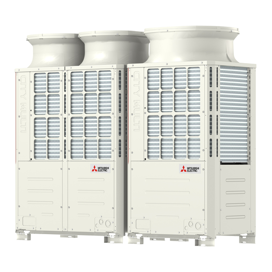
[3-1 External Appearance and Refrigerant Circuit Components of Outdoor Unit ] External Appearance and Refrigerant Circuit Components of 3 Major Components, Their Functions and Refrigerant Circuits Outdoor Unit 3-1-1 External Appearance of Outdoor Unit (1) PUHY-EP200, EP250YKM-A Fan guard Fan guard Fin guard Fin guard Control box... - Page 61 [3-1 External Appearance and Refrigerant Circuit Components of Outdoor Unit ] (2) PUHY-EP300, EP350, EP400, EP450YKM-A Fan guards Fan guards Fans Fans Side panel Side panel Fin guard Fin guard Control box Control box Fan box Fan box Heat exchanger Heat exchanger Side panel Side panel...
-
Page 62: Outdoor Unit Refrigerant Circuits
[3-1 External Appearance and Refrigerant Circuit Components of Outdoor Unit ] 3-1-2 Outdoor Unit Refrigerant Circuits (1) PUHY-EP200YKM-A High-pressure switch (63H1) Solenoid valve (SV2) High-pressure sensor (63HS1) Low-pressure sensor (63LS) Check valve Check valve 4-way valve (21S4a) Accumulator 4-way valve (21S4b) Low-pressure check joint Linear expansion valve... - Page 63 [3-1 External Appearance and Refrigerant Circuit Components of Outdoor Unit ] (2) PUHY-EP250YKM-A Solenoid valve (SV2) High-pressure switch (63H1) High-pressure sensor (63HS1) Check valve 4-way valve (21S4b) Low-pressure sensor (63LS) 4-way valve (21S4a) Check valve Low-pressure check joint Linear expansion valve (LEV1) High-pressure check joint Accumulator...
- Page 64 [3-1 External Appearance and Refrigerant Circuit Components of Outdoor Unit ] (3) PUHY-EP300, EP350, EP400, EP450YKM-A 4-way valve (21S4a) 4-way valve (21S4c) 2-way valve Linear expansion valve (SV5b) Low-pressure sensor (63LS) (LEV1) 4-way valve Linear expansion valve High-pressure sensor (63HS1) (21S4b) Solenoid (LEV2)
-
Page 65: Outdoor Unit Refrigerant Circuit Diagrams
[3-2 Outdoor Unit Refrigerant Circuit Diagrams ] Outdoor Unit Refrigerant Circuit Diagrams (1) PUHY-EP200, EP250 models 21S4b 21S4a 63H1 63HS1 63LS MOTOR SV1a Comp SV5b LEV1 LEV2 (2) PUHY-EP300, EP350, EP400, EP450 models 21S4c 21S4b HEX2 21S4a FAN2 (HEX2) 63LS MOTOR 63HS1 63H1... -
Page 66: Functions Of The Major Components Of Outdoor Unit
[3-3 Functions of the Major Components of Outdoor Unit ] Functions of the Major Components of Outdoor Unit Part Symbols Notes Usage Specifications Check method name (functions) Com- Adjusts the amount of circulating EP200, EP200 models pressor (Comp1) refrigerant by adjusting the operat- Low-pressure shell scroll ing frequency based on the oper- compressor... - Page 67 [3-3 Functions of the Major Components of Outdoor Unit ] Part Symbols Notes Usage Specifications Check method name (functions) Thermis- 1) Detects discharge air temper- Degrees Celsius Resistance check (Discharge) ature = 7.465k = 4057 2) Provides high-pressure pro- 25/120 tection 7.465 4057...
- Page 68 [3-3 Functions of the Major Components of Outdoor Unit ] Part Symbols Notes Usage Specifications Check method name (functions) Sole- SV1a 1) High/low pressure bypass at AC220-240V Continuity check noid Discharge- Open while being powered/ with a tester start-up and stopping, and valve suction closed while not being pow-...
-
Page 69: Functions Of The Major Components Of Indoor Unit
[3-4 Functions of the Major Components of Indoor Unit ] Functions of the Major Components of Indoor Unit Part Symbol Notes Usage Specification Check method Name (functions) Linear 1) Adjusts superheat at the DC12V Refer to the section expan- Opening of stepping motor "Continuity Test with a indoor heat exchanger sion valve... -
Page 70: Chapter 4 Electrical Components And Wiring Diagrams
Chapter 4 Electrical Components and Wiring Diagrams Outdoor Unit Circuit Board Arrangement..................63 4-1-1 Outdoor Unit Control Box........................63 4-1-2 Fan Box..............................64 Outdoor Unit Circuit Board Components ..................65 4-2-1 Control Board............................65 4-2-2 M-NET Board (Transmission Power Supply Board) ................66 4-2-3 INV Board ............................. - Page 71 - 62 - HWE12050...
-
Page 72: Outdoor Unit Circuit Board Arrangement
[4-1 Outdoor Unit Circuit Board Arrangement ] Outdoor Unit Circuit Board Arrangement 4 Electrical Components and Wiring Diagrams 4-1-1 Outdoor Unit Control Box <HIGH VOLTAGE WARNING> Control box houses high-voltage parts. When opening or closing the front panel of the control box, do not let it come into contact with any of the internal components. -
Page 73: Fan Box
[4-1 Outdoor Unit Circuit Board Arrangement ] 4-1-2 Fan Box (1) PUHY-EP300, EP350, EP400, EP450YKM-A FAN board Connect board Note 1) 1. Handle the fan box with care. If the front or the bottom panel becomes damaged, water or dust may enter the fan box, dam- aging its internal parts. -
Page 74: Outdoor Unit Circuit Board Components
[4-2 Outdoor Unit Circuit Board Components ] Outdoor Unit Circuit Board Components 4-2-1 Control Board *For information about the display of SW4 function settings, refer to the following page(s). [5-1-1 Outdoor Unit Switch Func- tions and Factory Settings](page 77) - 65 - HWE12050... -
Page 75: M-Net Board (Transmission Power Supply Board)
[4-2 Outdoor Unit Circuit Board Components ] 4-2-2 M-NET Board (Transmission Power Supply Board) CNS2 CNIT Transmission line input/output for 12VDC input CN04 centralized control system CN102 Bus voltage input 5VDC input Power supply output for centralized control system Power supply detection output Indoor/outdoor transmission line input/output Power supply ON/OFF Grounding... -
Page 76: Inv Board
[4-2 Outdoor Unit Circuit Board Components ] 4-2-3 INV Board 1) When opening or closing the front panel of the control box, do not let it come into contact with any of the internal components. Before inspecting the inside of the control box, turn off the power, keep the unit off for at least 10 minutes, and confirm that the capacitor voltage (inverter main circuit) has dropped to 20 VDC or less. -
Page 77: Fan Board
[4-2 Outdoor Unit Circuit Board Components ] 4-2-4 Fan Board 1) When opening or closing the front panel of the control box, do not let it come into contact with any of the internal components. Before inspecting the inside of the control box, turn off the power, keep the unit off for at least 10 minutes, and confirm that the capacitor voltage (inverter main circuit) has dropped to 20 VDC or less. -
Page 78: Noise Filter
[4-2 Outdoor Unit Circuit Board Components ] 4-2-5 Noise Filter Output Output (Rectified L2-N current) (Rectified L2-N current) Surge absorber circuit Surge absorber circuit Short circuit Short circuit Grounding F1,F2,F3,F4 Fuse 250VAC 6.3A Output Grounding CN1A Input CN1B TB21 TB22 TB23 TB24 Input... -
Page 79: Connect Board
[4-2 Outdoor Unit Circuit Board Components ] 4-2-6 Connect Board (1) PUHY-EP300, EP350, EP400, EP450YKM-A 1) When opening or closing the front panel of the control box, do not let it come into contact with any of the internal components. Before inspecting the inside of the control box, turn off the power, keep the unit off for at least 10 minutes, and confirm that the capacitor voltage (inverter main circuit) has dropped to 20 VDC or less. -
Page 80: Outdoor Unit Electrical Wiring Diagrams
[4-3 Outdoor Unit Electrical Wiring Diagrams ] Outdoor Unit Electrical Wiring Diagrams (1) PUHY-EP200, EP250 models - 71 - HWE12050... - Page 81 [4-3 Outdoor Unit Electrical Wiring Diagrams ] (2) PUHY-EP300, EP350, EP400, EP450 models - 72 - HWE12050...
-
Page 82: Transmission Booster Electrical Wiring Diagrams
[4-4 Transmission Booster Electrical Wiring Diagrams ] Transmission Booster Electrical Wiring Diagrams Terminal block for power supply (TB1) 250V 5A Red Red Red Black White White Green/Yellow 220 - 240VAC Varistor Noise filter Black White White White White Varistor Green Black Stabilized power supply Blue... - Page 83 [4-4 Transmission Booster Electrical Wiring Diagrams ] - 74 - HWE12050...
-
Page 84: Chapter 5 Control
Chapter 5 Control Dipswitch Functions and Factory Settings ..................77 5-1-1 Outdoor Unit Switch Functions and Factory Settings ................77 5-1-2 Indoor Unit Switch Functions and Factory Settings ................80 5-1-3 Remote Controller Switch Functions and Factory Settings..............81 Outdoor Unit Control .......................... 83 5-2-1 Overview ............................... - Page 85 - 76 - HWE12050...
-
Page 86: Dipswitch Functions And Factory Settings
[5-1 Dipswitch Functions and Factory Settings ] Dipswitch Functions and Factory Settings 5 Control 5-1-1 Outdoor Unit Switch Functions and Factory Settings (1) Control board Function according to switch setting Units that require Switch Function Switch setting timing switch setting (Note 2) Unit address set- Set to 00 or 51-100 with the dial switch... - Page 87 [5-1 Dipswitch Functions and Factory Settings ] Function according to switch setting Units that require Switch Function Switch setting timing switch setting OFF (LED3 Unlit) ON (LED3 Lit) (Note 2) Refer to the following page(s). [9 LED Sta- 1-10 Self-diagnosis/operation SW6-10: tus Indicators on the Outdoor Unit Circuit Anytime after power on...
- Page 88 [5-1 Dipswitch Functions and Factory Settings ] (2) INV board Functions are switched with the following connector. Function according to connec- Connector Function Setting timing Enabled Disabled CN6 short- Enabling/disabling the following error Error detec- Error detec- Anytime after power on circuit con- detection functions;...
-
Page 89: Indoor Unit Switch Functions And Factory Settings
[5-1 Dipswitch Functions and Factory Settings ] 5-1-2 Indoor Unit Switch Functions and Factory Settings (1) Dipswitches 1) SW1,3 Function according to switch setting Switch setting timing Switch Function Notes Set to ON (built-in sensor on the remote controller) Room temperature Built-in sensor on Indoor unit inlet on All Fresh (PEFY-VMH-F) model units... -
Page 90: Remote Controller Switch Functions And Factory Settings
[5-1 Dipswitch Functions and Factory Settings ] (2) Address switch Actual indoor unit address setting varies in different systems. Refer to the installation manual for the outdoor unit for details on how to make the address setting. Each address is set with a combination of the settings for the 10's digit and 1's digit. (Example) When setting the address to "3", set the 1's digit to 3, and the 10's digit to 0. - Page 91 [5-1 Dipswitch Functions and Factory Settings ] (2) ME remote controller (PAR-F27MEA) Set the address of the remote controller with the rotary switch. Rotary switch 10's digit 1's digit (left) (right) Remote controller unit Example: In case of address 108 Address setting range Setting method Main remote controller...
-
Page 92: Outdoor Unit Control
[5-2 Outdoor Unit Control ] Outdoor Unit Control 5-2-1 Overview The outdoor units are designated as OC, OS1 and OS2 in the order of capacity from large to small (if two or more units have the same capacity, in the order of address from small to large). The setting of outdoor unit can be verified by using the self-diagnosis switch (SW4). -
Page 93: Refrigerant Bypass Control
[5-2 Outdoor Unit Control ] 5-2-5 Refrigerant Bypass Control Bypass solenoid valves (SV1a), which bypass the high- and low- pressure sides, perform the following functions. (1) Bypass solenoid valve (SV1a) (ON = Open), (SV9) (ON = Open), (SV2) (ON = Open) SV1a Operation When starting-up the compressor of each... -
Page 94: Frequency Control
[5-2 Outdoor Unit Control ] 5-2-6 Frequency Control Depending on the capacity required, the frequency of the compressor is controlled to keep constant evaporation temperature (0°C [32°F] = 0.71 MPa [103 psi]) during cooling operation, and condensing temperature (49°C [120°F] = 2.88 MPa [418 psi]) during heating operation. -
Page 95: Defrost Operation Control
[5-2 Outdoor Unit Control ] 5-2-7 Defrost Operation Control (1) Starting the defrost operation The defrost cycle will start when all of the three conditions (outside temperature, cumulative compressor operation time, and pipe temperature) under <Condition 1>, <Condition 2>, or <Condition 3> are met. Condition 1 Condition 2 Condition 3... - Page 96 [5-2 Outdoor Unit Control ] (3) Stopping the defrost operation The defrost cycle ends when 12 minutes have passed since the beginning of the cycle, or when the pipe temperature (TH3) has been continuously detected for 4 minutes (when SW4 (916) is set to OFF) or 2 minutes (when SW4 (916) is set to ON) that exceeds the values in the table below.
-
Page 97: Refrigerant Recovery Control
[5-2 Outdoor Unit Control ] 5-2-8 Refrigerant Recovery Control Recovery of refrigerant is performed during heating operation to prevent the refrigerant from accumulating inside the unit while it is stopped (unit in fan mode), or inside the indoor unit that is in cooling mode or in heating mode with thermo off. It is also performed during cooling operation to prevent an excessive amount of refrigerant from accumulating in the outdoor heat ex- changer. -
Page 98: Outdoor Unit Fan Control
[5-2 Outdoor Unit Control ] 5-2-9 Outdoor Unit Fan Control (1) Control method Depending on the capacity required, the rotation speed of the outdoor unit fan is controlled by the inverter, targeting a constant evaporation temperature of (0°C [32°F]= 0.71 MPa [103 psi]) during cooling operation and constant condensing temperature of (49°C [120°F]= 2.88 MPa [418 psi]) during heating operation. - Page 99 [5-2 Outdoor Unit Control ] (2) EP400 - EP600YSKM models Initial startup mode starts. The compressor on the OC starts up. 60Hz The total operating load of the indoor unit after 5 minutes of operation is P250 or above. (*1 Qj The compressor on the OC starts up.
- Page 100 [5-2 Outdoor Unit Control ] (3) EP650 - EP900YSKM models Initial startup mode starts. The compressor on the OC starts up. 60Hz The total operating load of the indoor unit after 5 minutes of operation is P250 or above. ( *1 The total operating load of the indoor unit after 5 minutes of operation is between P250 and P1000.
-
Page 101: Emergency Operation Mode
[5-2 Outdoor Unit Control ] 5-2-13 Emergency Operation Mode 1. Problems with the outdoor unit Emergency operation mode is a mode in which outdoor units that are operating normally take over the operation of the out- door units that are experiencing problems. (EP400-EP600YSKM models go into an emergency operation mode when one outdoor unit is in trouble, and EP650-EP900YSKM models go into an emergency operation mode when one or two outdoor units are in trouble.) This mode can be started by performing an error reset via the remote controller. - Page 102 [5-2 Outdoor Unit Control ] (2) Ending the emergency operation 1) End conditions When one of the following conditions is met, emergency operation stops, and the unit makes an error stop. When the integrated operation time of compressor in cooling mode has reached four hours. When the integrated operation time of compressor in heating mode has reached two hours.
- Page 103 [5-2 Outdoor Unit Control ] Emergency operation pattern (2 outdoor units) OC failure OS failure pattern pattern Trouble Normal Normal Trouble Cooling Emergency Permitted Permitted operation Heating Permitted Permitted Capacity that matches Maximum total capacity the total capacity of the of indoor units (Note 1) operable outdoor units Emergency operation pattern (3 outdoor units)
-
Page 104: Operation Mode
[5-2 Outdoor Unit Control ] 5-2-14 Operation Mode (1) Indoor unit operation mode The operation mode can be selected from the following 5 modes using the remote controller. Cooling mode Heating mode Dry mode Fan mode Stopping mode (2) Outdoor unit operation mode Cooling mode All indoor units in operation are in cooling mode. -
Page 105: Operation Flowcharts
[5-3 Operation Flowcharts ] Operation Flowcharts 5-3-1 Operation Sequence Flowchart (1) Indoor unit (cooling, heating, dry, fan mode) Start Normal operation Error Breaker Unit in the stopped state turned on From outdoor unit Operation SW turned on 1. Protection function self-holding cancelled. - Page 106 [5-3 Operation Flowcharts ] (2) Outdoor unit (cooling and heating modes) Start Normal operation Error Breaker Unit in the stopped state turned on "HO" / "PLEASE WAIT" blinks on the remote controller *Note 1 Indoor units registered to the remote controller From indoor unit Operation command...
-
Page 107: Actions Performed In Different Modes
[5-3 Operation Flowcharts ] 5-3-2 Actions Performed in Different Modes (1) Cooling operation Cooling operation Normal operation During test run mode 4-way valve OFF Unit in the stopped state Indoor unit fan *Note 1 operation Test run mode Thermostat ON 3-minute restart prevention 1. - Page 108 [5-3 Operation Flowcharts ] (2) Heating operation Normal operation Defrost operation Heating operation Unit in the stopped state *Note 1,2 During test run mode Defrost operation 4-way valve ON 4-way valve OFF 1. Indoor unit fan stops 2. Inverter defrost frequency control Test run mode 3.
- Page 109 [5-3 Operation Flowcharts ] (3) Dry operation Dry operation Normal operation Thermostat ON 4-way valve OFF Unit in the stopped state Test run mode *Note 2 Thermostat ON Suction temperature 18°C[64°F] *Note 1 1. Indoor unit fan stop 1. Outdoor unit (compressor) 2.
-
Page 110: Chapter 6 Test Run
Chapter 6 Test Run Read before Test Run........................103 MA and ME Remote Controller Functions and Specifications ............. 104 6-2-1 Function/Specification Comparison ....................104 6-2-2 Local Remote Controller Selection Tips....................104 Making the Group and Interlock Settings from an ME Remote Controller ........105 6-3-1 Overview ............................. - Page 111 - 102 - HWE12050...
-
Page 112: Read Before Test Run
[6-1 Read before Test Run ] Read before Test Run 6 Test Run (1) Check for refrigerant leak and loose cables and connectors. (2) When opening or closing the front panel of the control box, do not let it come into contact with any of the internal components. -
Page 113: Ma And Me Remote Controller Functions And Specifications
[6-2 MA and ME Remote Controller Functions and Specifications ] MA and ME Remote Controller Functions and Specifications There are two types of remote controllers: ME remote controller, which is connected on the indoor-outdoor transmission line, and MA remote controller, which is connected to each indoor unit. 6-2-1 Function/Specification Comparison *1*2... -
Page 114: Making The Group And Interlock Settings From An Me Remote Controller
[6-3 Making the Group and Interlock Settings from an ME Remote Controller ] Making the Group and Interlock Settings from an ME Remote Controller 6-3-1 Overview Make the following settings to perform a group operation of units that are connected to different outdoor units or to manually set up the indoor/outdoor unit address. - Page 115 [6-3 Making the Group and Interlock Settings from an ME Remote Controller ] (A) Group Settings (B) Interlock Settings Bring up the Group Setting window. Bring up the Interlock Setting window. -Press and hold buttons [FILTER] and -Press button ] to bring up the following display. simultaneously for 2 seconds to bring up the display as Press again to go back to the Group Setting window as shown shown below.
-
Page 116: Address Search
[6-3 Making the Group and Interlock Settings from an ME Remote Controller ] 6-3-3 Address Search To search for the address of indoor units that have been entered into the remote controller, follow steps (A) To search group settings (B) Interlock setting search After performing step , proceed as follows: Bring up the Group Setting window. -
Page 117: Address Deletion
[6-3 Making the Group and Interlock Settings from an ME Remote Controller ] 6-3-4 Address Deletion The addresses of the indoor units that have been entered into the remote controller can be deleted by deleting the group settings. The interlock settings between units can be deleted by deleting the interlock settings. Follow the steps in section 6-3-3 Address Search to find the address to be deleted and perform deletion with the address being displayed in the display window. -
Page 118: Selecting Remote Controller Functions From An Me Remote Controller
[6-4 Selecting Remote Controller Functions from an ME Remote Controller ] Selecting Remote Controller Functions from an ME Remote Controller In the remote controller function selection mode, the settings for four types of functions can be made or changed as necessary. 1) Skip-Auto-Mode setting The automatic operation mode that is supported by some simultaneous cooling/heating type units can be made unselectable via the ME remote controller. - Page 119 [6-4 Selecting Remote Controller Functions from an ME Remote Controller ] [Operation Procedures] 1. Press the [ON/OFF] button on the remote controller to bring the unit to a stop. The display will appear as shown in the previous page (Normal display).
-
Page 120: Making Interlock Settings From An Ma Remote Controller
[6-5 Making Interlock Settings from an MA Remote Controller ] Making Interlock Settings from an MA Remote Controller LOSSNAY interlock setting (Make this setting only when necessary.) 6-5-1 MA Remote Controller (PAR-31MAA) This setting is required only when the operation of City Multi units is interlocked with LOSSNAY units. This setting is not available for the Mr. -
Page 121: Ma Remote Controller (Par-21Maa)
[6-5 Making Interlock Settings from an MA Remote Controller ] 6-5-2 MA Remote Controller (PAR-21MAA) * When the upper controller is connected, make the setting using the upper controller. NOTE: When using LOSSNAY units in conjunction, interlock the addresses of all indoor units within the group and address of LOSSNAY units. Perform this operation to enter the interlock setting between the LOSSNAY and the indoor units to which the remote controller is connected, or to search and delete registered information. - Page 122 [6-5 Making Interlock Settings from an MA Remote Controller ] < 2. Search Procedures > To search for the LOSSNAY unit that is interlocked with a particular indoor unit, enter the address of the indoor unit into the remote controller that is connected to it.
-
Page 123: Ma Simple Remote Controller
[6-5 Making Interlock Settings from an MA Remote Controller ] 6-5-3 MA Simple Remote Controller Make this setting only when interlocked operation with LOSSNAY is necessary with CITY MULTI models. Perform this operation when you want to register the LOSSNAY, confirm the registered units, or delete the registered units controlled by the remote controller. - Page 124 [6-5 Making Interlock Settings from an MA Remote Controller ] <1. Registration procedure> Set the address of the indoor unit to be interlocked with the LOSSNAY unit using the buttons. (01 to 50) After setting, press the button and set the Lossnay address you want to register by operating the buttons.
- Page 125 [6-5 Making Interlock Settings from an MA Remote Controller ] <2. Confirmation procedure> Set the address of the indoor unit connected by the remote controller whose LOSSNAY you want to confirm using the buttons. (01 to 50) Press the button and button simultaneously for 2 seconds, and check the LOSSNAY address registered at the set indoor unit address.
-
Page 126: Changing The Room Temperature Detection Position
[6-6 Changing the Room Temperature Detection Position ] Changing the Room Temperature Detection Position 1. Selecting the position of temperature detection (Factory setting: SW1-1 on the controller board on the indoor unit is set to OFF.) To use the built-in sensor on the remote controller, set the SW1-1 on the controller board on the indoor unit to ON. Some models of remote controllers are not equipped with a built-in temperature sensor. -
Page 127: Test Run Method
[6-7 Test Run Method ] Test Run Method 6-7-1 MA Remote Controller (PAR-31MAA) (1) Remote controller button functions Function button The assignment of the function buttons varies depending on the screen. Follow the guide screen that will appear at the bottom of the screen (from the left, F1, F2, F3, and F4). - Page 128 [6-7 Test Run Method ] (3) Entering the maintenance information Model name, serial number, and dealer's phone number can be registered to the remote controller to be displayed on the screen when an error occurs. Step 1: Switching the remote controller screen to "Maintenance information" (Requires the maintenance password.
-
Page 129: Ma Remote Controller (Par-21Maa)
[6-7 Test Run Method ] 6-7-2 MA Remote Controller (PAR-21MAA) The figure shows an MA remote controller (PAR-21MAA). ON/OFF button Set Temperature buttons Down Fan Speed button TIME SUN MON TUE WED THU FRI SAT TIMER AFTER AFTER ERROR CODE FUNCTION FILTER WEEKLY... -
Page 130: Operation Characteristics And Refrigerant Charge
[6-8 Operation Characteristics and Refrigerant Charge ] Operation Characteristics and Refrigerant Charge It is important to have a clear understanding of the characteristics of refrigerant and the operating characteristics of air conditioners before attempting to adjust the refrigerant amount in a given system. The following table shows items of particular importance. -
Page 131: The Amount Of Refrigerant To Be Added
[6-9 Evaluating and Adjusting Refrigerant Charge ] 6-9-3 The Amount of Refrigerant to Be Added The amount of refrigerant that is shown in the table below is factory-charged to the outdoor units. The amount necessary for extended pipe (field piping) is not included and must be added on site. Outdoor unit model EP200 EP250... - Page 132 [6-9 Evaluating and Adjusting Refrigerant Charge ] 1) Maximum refrigerant charge There is a limit to the amount of refrigerant that can be charged into a unit. Regardless of the amount yielded by the formula above, observe the maximum refrigerant charge in the table below. Total index of the outdoor units EP200 EP250...
- Page 133 [6-9 Evaluating and Adjusting Refrigerant Charge ] (2) Example: PUHY-EP450YSKM-A 9.52 9.52 (3 m) (1 m) 9.52 (10 m) 15.88 (10 m) × Liquid separator 9.52 9.52 9.52 9.52 6.35 (10 m) (20 m) (10 m) (10 m) (10 m) 15.88 (30 m) model model...
-
Page 134: Refrigerant Charge Adjustment Mode
[6-9 Evaluating and Adjusting Refrigerant Charge ] 6-9-4 Refrigerant Charge Adjustment Mode Follow the procedures below to add or extract refrigerant as necessary depending on the operation mode. When the function switch (SW4 (922)) on the main board on the outdoor unit (OC only) is turned to ON, the unit goes into the refrigerant amount adjust mode, and the following sequence is followed. - Page 135 [6-9 Evaluating and Adjusting Refrigerant Charge ] Start Turn on SW4 (922) on the OC. Put all indoor units in the test run mode *Refer to the previous page for *Notes 1-4 in the chart. and run the units in cooling mode. Has the initial start-up mode been completed? Has it been at least...
-
Page 136: 6-10 The Following Symptoms Are Normal
[6-10 The Following Symptoms Are Normal ] 6-10 The Following Symptoms Are Normal Remote controller Symptoms Cause display The indoor unit does not start "Cooling (heating)" The unit cannot perform a heating (cooling) operation when other indoor after starting cooling (heating) icon blinks on the units on the same refrigerant system, are performing a cooling (heating) operation. -
Page 137: Standard Operation Data (Reference Data)
[6-11 Standard Operation Data (Reference Data) ] 6-11 Standard Operation Data (Reference Data) 6-11-1 Single Unit (High COP Unit) Outdoor unit model PUHY-EP200YKM-A PUHY-EP250YKM-A Indoor 26.7°C/19.4°C [80°F/67°F] 26.7°C/19.4°C [80°F/67°F] Ambient temperature DB/WB (cooling) Outdoor 35°C/- [95°F/-] 35°C/- [95°F/-] Indoor 21.1°C/- [70°F/-] 21.1°C/- [70°F/-] Ambient temperature DB/WB... - Page 138 [6-11 Standard Operation Data (Reference Data) ] Outdoor unit model PUHY-EP300YKM-A PUHY-EP350YKM-A Indoor 26.7°C/19.4°C [80°F/67°F] 26.7°C/19.4°C [80°F/67°F] Ambient temperature DB/WB (cooling) Outdoor 35°C/- [95°F/-] 35°C/- [95°F/-] Indoor 21.1°C/- [70°F/-] 21.1°C/- [70°F/-] Ambient temperature DB/WB (heating) Outdoor 8.3°C/6.1°C [47°F/43°F] 8.3°C/6.1°C [47°F/43°F] Number of units connected Unit Indoor unit...
- Page 139 [6-11 Standard Operation Data (Reference Data) ] Outdoor unit model PUHY-EP400YKM-A PUHY-EP450YKM-A Indoor 26.7°C/19.4°C [80°F/67°F] 26.7°C/19.4°C [80°F/67°F] Ambient temperature DB/WB (cooling) Outdoor 35°C/- [95°F/-] 35°C/- [95°F/-] Indoor 21.1°C/- [70°F/-] 21.1°C/- [70°F/-] Ambient temperature DB/WB (heating) Outdoor 8.3°C/6.1°C [47°F/43°F] 8.3°C/6.1°C [47°F/43°F] Number of units connected Unit Indoor unit...
-
Page 140: Dual Unit Combination (High Cop Unit)
[6-11 Standard Operation Data (Reference Data) ] 6-11-2 Dual Unit Combination (High COP Unit) Packaged unit model PUHY-EP400YSKM-A Outdoor unit model PUHY-EP200YKM-A PUHY-EP200YKM-A Indoor 26.7°C/19.4°C [80°F/67°F] Ambient temperature DB/WB (cooling) Outdoor 35°C/- [95°F/-] Indoor 21.1°C/- [70°F/-] Ambient temperature DB/WB (heating) Outdoor 8.3°C/6.1°C [47°F/43°F] Number of units connected... - Page 141 [6-11 Standard Operation Data (Reference Data) ] Packaged unit model PUHY-EP450YSKM-A Outdoor unit model PUHY-EP200YKM-A PUHY-EP250YKM-A Indoor 26.7°C/19.4°C [80°F/67°F] Ambient temperature DB/WB (cooling) Outdoor 35°C/- [95°F/-] Indoor 21.1°C/- [70°F/-] Ambient temperature DB/WB (heating) Outdoor 8.3°C/6.1°C [47°F/43°F] Number of units connected Unit Indoor unit Number of units in operation...
- Page 142 [6-11 Standard Operation Data (Reference Data) ] Packaged unit model PUHY-EP500YSKM-A Outdoor unit model PUHY-EP200YKM-A PUHY-EP300YKM-A Indoor 26.7°C/19.4°C [80°F/67°F] Ambient temperature DB/WB (cooling) Outdoor 35°C/- [95°F/-] Indoor 21.1°C/- [70°F/-] Ambient temperature DB/WB (heating) Outdoor 8.3°C/6.1°C [47°F/43°F] Number of units connected Unit Indoor unit Number of units in operation...
- Page 143 [6-11 Standard Operation Data (Reference Data) ] Packaged unit model PUHY-EP550YSKM-A Outdoor unit model PUHY-EP250YKM-A PUHY-EP300YKM-A Indoor 26.7°C/19.4°C [80°F/67°F] Ambient temperature DB/WB (cooling) Outdoor 35°C/- [95°F/-] Indoor 21.1°C/- [70°F/-] Ambient temperature DB/WB (heating) Outdoor 8.3°C/6.1°C [47°F/43°F] Number of units connected Unit Indoor unit Number of units in operation...
- Page 144 [6-11 Standard Operation Data (Reference Data) ] Packaged unit model PUHY-EP600YSKM-A Outdoor unit model PUHY-EP300YKM-A PUHY-EP300YKM-A Indoor 26.7°C/19.4°C [80°F/67°F] Ambient temperature DB/WB (cooling) Outdoor 35°C/- [95°F/-] Indoor 21.1°C/- [70°F/-] Ambient temperature DB/WB (heating) Outdoor 8.3°C/6.1°C [47°F/43°F] Number of units connected Unit Indoor unit Number of units in operation...
-
Page 145: Triple Unit Combination (High Cop Unit)
[6-11 Standard Operation Data (Reference Data) ] 6-11-3 Triple Unit Combination (High COP Unit) Packaged unit model PUHY-EP650YSKM-A Outdoor unit model PUHY-EP200YKM-A PUHY-EP200YKM-A PUHY-EP250YKM-A Indoor 26.7°C/19.4°C [80°F/67°F] Ambient temperature DB/WB (cooling) Outdoor 35°C/- [95°F/-] Indoor 21.1°C/- [70°F/-] Ambient temperature DB/WB (heating) Outdoor 8.3°C/6.1°C... - Page 146 [6-11 Standard Operation Data (Reference Data) ] Packaged unit model PUHY-EP700YSKM-A Outdoor unit model PUHY-EP200YKM-A PUHY-EP200YKM-A PUHY-EP300YKM-A Indoor 26.7°C/19.4°C [80°F/67°F] Ambient temperature DB/WB (cooling) Outdoor 35°C/- [95°F/-] Indoor 21.1°C/- [70°F/-] Ambient temperature DB/WB (heating) Outdoor 8.3°C/6.1°C [47°F/43°F] Number of units connected Unit Indoor unit Number of units in operation...
- Page 147 [6-11 Standard Operation Data (Reference Data) ] Packaged unit model PUHY-EP750YSKM-A Outdoor unit model PUHY-EP200YKM-A PUHY-EP250YKM-A PUHY-EP300YKM-A Indoor 26.7°C/19.4°C [80°F/67°F] Ambient temperature DB/WB (cooling) Outdoor 35°C/- [95°F/-] Indoor 21.1°C/- [70°F/-] Ambient temperature DB/WB (heating) Outdoor 8.3°C/6.1°C [47°F/43°F] Number of units connected Unit Indoor unit Number of units in operation...
- Page 148 [6-11 Standard Operation Data (Reference Data) ] Packaged unit model PUHY-EP800YSKM-A Outdoor unit model PUHY-EP200YKM-A PUHY-EP300YKM-A PUHY-EP300YKM-A Indoor 26.7°C/19.4°C [80°F/67°F] Ambient temperature DB/WB (cooling) Outdoor 35°C/- [95°F/-] Indoor 21.1°C/- [70°F/-] Ambient temperature DB/WB (heating) Outdoor 8.3°C/6.1°C [47°F/43°F] Number of units connected Unit Indoor unit Number of units in operation...
- Page 149 [6-11 Standard Operation Data (Reference Data) ] Packaged unit model PUHY-EP850YSKM-A Outdoor unit model PUHY-EP250YKM-A PUHY-EP300YKM-A PUHY-EP300YKM-A Indoor 26.7°C/19.4°C [80°F/67°F] Ambient temperature DB/WB (cooling) Outdoor 35°C/- [95°F/-] Indoor 21.1°C/- [70°F/-] Ambient temperature DB/WB (heating) Outdoor 8.3°C/6.1°C [47°F/43°F] Number of units connected Unit Indoor unit Number of units in operation...
- Page 150 [6-11 Standard Operation Data (Reference Data) ] Packaged unit model PUHY-EP900YSKM-A Outdoor unit model PUHY-EP300YKM-A PUHY-EP300YKM-A PUHY-EP300YKM-A Indoor 26.7°C/19.4°C [80°F/67°F] Ambient temperature DB/WB (cooling) Outdoor 35°C/- [95°F/-] Indoor 21.1°C/- [70°F/-] Ambient temperature DB/WB (heating) Outdoor 8.3°C/6.1°C [47°F/43°F] Number of units connected Unit Indoor unit Number of units in operation...
- Page 151 [6-11 Standard Operation Data (Reference Data) ] - 142 - HWE12050...
-
Page 152: Chapter 7 Troubleshooting Using Error Codes
Chapter 7 Troubleshooting Using Error Codes Error Code and Preliminary Error Code Lists ................145 Error Code Definitions and Solutions: Codes [0 - 999] ..............148 7-2-1 Error Code [0403] ..........................148 Error Code Definitions and Solutions: Codes [1000 - 1999] ............149 7-3-1 Error Code [1102] .......................... - Page 153 7-7-10 Error Codes [5305, 5306] Detail Code 133..................178 7-7-11 Error Codes [5305, 5306] Detail Code 134..................179 7-7-12 Error Code [5701] ..........................179 Error Code Definitions and Solutions: Codes [6000 - 6999] ............180 7-8-1 Error Code [6201] ..........................180 7-8-2 Error Code [6202] ..........................
-
Page 154: Error Code And Preliminary Error Code Lists
[7-1 Error Code and Preliminary Error Code Lists ] Error Code and Preliminary Error Code Lists 7 Troubleshooting Using Error Codes Searched unit Error Prelimi- (prelim- Error nary inary) Error code definition Notes Code error detail code code 4300 0403 4305 Serial communication error/Panel communication error (page 148) - Page 155 [7-1 Error Code and Preliminary Error Code Lists ] Searched unit Error Prelimi- (prelim- Error nary inary) Error code definition Notes Code error detail code code Return air temperature (page 173) (TH21) 5101 1202 Temperature sensor fault OA processing unit inlet (page 173) temperature (TH4) Indoor unit pipe tempera-...
- Page 156 [7-1 Error Code and Preliminary Error Code Lists ] Searched unit Error Prelimi- (prelim- Error nary inary) Error code definition Notes Code error detail code code 6202 Remote controller board fault (clock IC error) (page 180) 6600 Address overlap (page 181) 6601 Polarity setting error (page 181)
-
Page 157: Error Code Definitions And Solutions: Codes [0 - 999]
[7-2 Error Code Definitions and Solutions: Codes [0 - 999] ] Error Code Definitions and Solutions: Codes [0 - 999] 7-2-1 Error Code [0403] 1. Error code definition Serial communication error 2. Error definition and error detection method Serial communication error between the control board and the INV board on the compressor, and between the control board and the Fan board Detail code 1: Between the control board and the INV board Detail code 5, 6: Between the control board and the Fan board... -
Page 158: Error Code Definitions And Solutions: Codes [1000 - 1999]
[7-3 Error Code Definitions and Solutions: Codes [1000 - 1999] ] Error Code Definitions and Solutions: Codes [1000 - 1999] 7-3-1 Error Code [1102] 1. Error code definition Discharge temperature fault 2. Error definition and error detection method 1) If the discharge temperature of 120 °C [248°F] or more is detected during the above operation (the first detection), the outdoor unit stops once, turns to anti-restart mode for 3 minutes, and restarts after 3 minutes automatically. -
Page 159: Error Code [1301]
[7-3 Error Code Definitions and Solutions: Codes [1000 - 1999] ] 7-3-2 Error Code [1301] 1. Error code definition Low pressure fault 2. Error definition and error detection method When starting the compressor from Stop Mode for the first time if low pressure reads 0.098MPa [14psi] immediately before start-up, the operation immediately stops. -
Page 160: Error Code [1302] (During Operation)
[7-3 Error Code Definitions and Solutions: Codes [1000 - 1999] ] 7-3-3 Error Code [1302] (during operation) 1. Error code definition High pressure fault 1 (Outdoor unit) 2. Error definition and error detection method 1) If the pressure of 3.78MPa [548psi] or higher is detected by the pressure sensor during operation (the first detection), the out- door stops once, turns to antirestart mode for 3 minutes, and restarts after 3 minutes automatically. -
Page 161: Error Code [1302] (At Startup)
[7-3 Error Code Definitions and Solutions: Codes [1000 - 1999] ] 7-3-4 Error Code [1302] (at startup) 1. Error code definition High pressure fault 2 (Outdoor unit) 2. Error definition and error detection method If the pressure of 0.098MPa [14psi] or lower is registered on the pressure sensor immediately before start-up, it will trigger an abnormal stop, and error code "1302"... -
Page 162: Error Code Definitions And Solutions: Codes [2000 - 2999]
[7-4 Error Code Definitions and Solutions: Codes [2000 - 2999] ] Error Code Definitions and Solutions: Codes [2000 - 2999] 7-4-1 Error Code [2500] (Models with a drain sensor) 1. Error code definition Drain sensor submergence 2. Error definition and error detection method 1) If an immersion of the drain sensor in the water is detected while the unit is in any mode other than the Cool/Dry mode and when the drain pump goes from OFF to ON, this condition is considered preliminary water leakage. -
Page 163: Error Code [2500] (Models With A Float Switch)
[7-4 Error Code Definitions and Solutions: Codes [2000 - 2999] ] 7-4-2 Error Code [2500] (Models with a float switch) 1. Error code definition Drain sensor submergence 2. Error definition and error detection method 1) If an immersion of the float switch in the water is detected while the unit is in any mode other than the Cool/Dry mode and when the drain pump goes from OFF to ON, this condition is considered preliminary water leakage. -
Page 164: Error Code [2502] (Models With A Drain Sensor)
[7-4 Error Code Definitions and Solutions: Codes [2000 - 2999] ] 7-4-3 Error Code [2502] (Models with a drain sensor) 1. Error code definition Drain pump fault 2. Error definition and error detection method 1) Make the drain sensor thermistor self-heat. If the temperature rise is small, it is interpreted that the sensor is immersed in water. -
Page 165: Error Code [2502] (Models With A Float Switch)
[7-4 Error Code Definitions and Solutions: Codes [2000 - 2999] ] 7-4-4 Error Code [2502] (Models with a float switch) 1. Error code definition Drain pump fault 2. Error definition and error detection method 1) The immersion of sensor tip in water is detected by the ON/OFF signal from the float switch. ∗Submergence of the sensor When it is detected that the float switch has been ON for 15 seconds, it is interpreted that the sensor tip is immersed in water. -
Page 166: Error Code [2503]
[7-4 Error Code Definitions and Solutions: Codes [2000 - 2999] ] 7-4-5 Error Code [2503] 1. Error code definition Drain sensor (Thd) fault 2. Error definition and error detection method If the open or short circuit of the thermistor has been detected for 30 seconds, this condition is considered to be a preliminary error, and the unit goes into the 3-minute restart delay mode. -
Page 167: Error Code [2600]
[7-4 Error Code Definitions and Solutions: Codes [2000 - 2999] ] 7-4-6 Error Code [2600] 1. Error code definition Water leakage 2. Cause, check method and remedy Check that water does not leak from the pipes in such as the humidifier. 7-4-7 Error Code [2601] 1. -
Page 168: Error Code Definitions And Solutions: Codes [3000 - 3999]
[7-5 Error Code Definitions and Solutions: Codes [3000 - 3999] ] Error Code Definitions and Solutions: Codes [3000 - 3999] 7-5-1 Error Code [3121] 1. Error code definition Out-of-range outside air temperature 2. Error definition and error detection method When the thermistor temperature of -28°C[-18°F] or below has continuously been detected for 3 minutes during heating op- eration (during compressor operation), the unit makes an error stop and "3121"... -
Page 169: Error Code Definitions And Solutions: Codes [4000 - 4999]
[7-6 Error Code Definitions and Solutions: Codes [4000 - 4999] ] Error Code Definitions and Solutions: Codes [4000 - 4999] 7-6-1 Error Code [4102] 1. Error code definition Open phase 2. Error definition and error detection method An open phase of the power supply (L1 phase, N phase) was detected at power on. The L3 phase current is outside of the specified range. -
Page 170: Error Code [4106]
[7-6 Error Code Definitions and Solutions: Codes [4000 - 4999] ] 7-6-2 Error Code [4106] 1. Error code definition <Transmission power supply fault Error detail code FF (Outdoor unit)> 2. Error definition and error detection method Transmission power output failure 3. -
Page 171: Error Code [4115]
[7-6 Error Code Definitions and Solutions: Codes [4000 - 4999] ] 7-6-4 Error Code [4115] 1. Error code definition Power supply signal sync error 2. Error definition and error detection method The frequency cannot be determined when the power is switched on. 3. -
Page 172: Error Code [4121]
[7-6 Error Code Definitions and Solutions: Codes [4000 - 4999] ] 7-6-6 Error Code [4121] 1. Error code definition Function setting error 2. Error source, cause, check method and remedy Error source Cause Check method and remedy Outdoor unit (1) Dip switch setting error on the control board Check the SW6-1 setting on the control board (2) Connector connection error on the control Check that nothing is connected to the connector... -
Page 173: Error Codes [4220, 4225, 4226] Detail Code 108
[7-6 Error Code Definitions and Solutions: Codes [4000 - 4999] ] 7-6-7 Error Codes [4220, 4225, 4226] Detail Code 108 1. Error code definition Abnormal bus voltage drop (Detail code 108) 2. Error definition and error detection method If Vdc 289V or less is detected during Inverter operation. (S/W detection) 3. - Page 174 [7-6 Error Code Definitions and Solutions: Codes [4000 - 4999] ] In case of 4226 (On the EP300, EP350, EP400, and EP450 models, this error code relates to the fan board in the fan box.) Check the voltage at CNVDC on the Fan board while the inverter is stopped and if it is 420 V or above, check the following items.
-
Page 175: Error Codes [4220, 4225, 4226] Detail Code 109
[7-6 Error Code Definitions and Solutions: Codes [4000 - 4999] ] 7-6-8 Error Codes [4220, 4225, 4226] Detail Code 109 1. Error code definition Abnormal bus voltage rise (Detail code 109) 2. Error definition and error detection method If Vdc 830V is detected during inverter operation. -
Page 176: Error Codes [4220, 4225, 4226] Detail Code 131
[7-6 Error Code Definitions and Solutions: Codes [4000 - 4999] ] 7-6-10 Error Codes [4220, 4225, 4226] Detail Code 131 1. Error code definition Low bus voltage at startup (Detail code 131) 2. Error definition and error detection method When Vdc 160 V is detected just before the inverter operation. -
Page 177: Error Code [4240]
[7-6 Error Code Definitions and Solutions: Codes [4000 - 4999] ] 7-6-12 Error Code [4240] 1. Error code definition Overload protection 2. Error definition and error detection method If the output current of "(Iac) >Imax (Arms)" or "THHS > 100°C [212°F] " is continuously detected for 10 minutes or more during inverter operation. -
Page 178: Error Codes [4250, 4255, 4256] Detail Code 101
[7-6 Error Code Definitions and Solutions: Codes [4000 - 4999] ] 7-6-13 Error Codes [4250, 4255, 4256] Detail Code 101 1. Error code definition IPM error (Detail code 101) 2. Error definition and error detection method In the case of 4250 Overcurrent is detected by the overcurrent detection resistor (RSH) on the INV board. -
Page 179: Error Code [4250] Detail Codes 106 And 107
[7-6 Error Code Definitions and Solutions: Codes [4000 - 4999] ] 7-6-14 Error Code [4250] Detail Codes 106 and 107 1. Error code definition Instantaneous overcurrent (Detail code 106) Overcurrent (effective value) (Detail code 107) 2. Error definition and error detection method EP200 and EP250 models Overcurrent 38 Apeak or 23 Arms and above is detected by the current sensor. -
Page 180: Error Codes [4250, 4255, 4256] Detail Code 104
[7-6 Error Code Definitions and Solutions: Codes [4000 - 4999] ] 7-6-15 Error Codes [4250, 4255, 4256] Detail Code 104 1. Error code definition Short-circuited IPM/Ground fault (Detail code 104) 2. Error definition and error detection method When IPM/IGBT short damage or grounding on the load side is detected just before starting the inverter. 3. -
Page 181: Error Codes [4250, 4255, 4256] Detail Code 105
[7-6 Error Code Definitions and Solutions: Codes [4000 - 4999] ] 7-6-16 Error Codes [4250, 4255, 4256] Detail Code 105 1. Error code definition Overcurrent error due to short-circuited motor (Detail code 105) 2. Error definition and error detection method When a short is detected on the load side just before starting the inverter operation. -
Page 182: Error Code Definitions And Solutions: Codes [5000 - 5999]
[7-7 Error Code Definitions and Solutions: Codes [5000 - 5999] ] Error Code Definitions and Solutions: Codes [5000 - 5999] 7-7-1 Error Codes [5101, 5102, 5103 5104] 1. Error code definition 5101 Return air temperature sensor (TH21) fault (Indoor unit) Return air temperature sensor (TH4) fault (OA processing unit) 5102 Pipe temperature sensor (TH22) fault (Indoor unit) -
Page 183: Error Codes [5102, 5103, 5104, 5105, 5106, 5107]
[7-7 Error Code Definitions and Solutions: Codes [5000 - 5999] ] 7-7-2 Error Codes [5102, 5103, 5104, 5105, 5106, 5107] 1. Error code definition 5102 HIC bypass circuit outlet temperature sensor (TH2) fault (Outdoor unit) 5103 Heat exchanger outlet temperature sensor (TH3) fault (Outdoor unit) 5104 Discharge temperature sensor (TH4) fault (Outdoor unit) 5105... -
Page 184: Error Code [5110]
[7-7 Error Code Definitions and Solutions: Codes [5000 - 5999] ] 7-7-3 Error Code [5110] 1. Error code definition Heatsink temperature sensor (THHS) fault (Detail code 01) 2. Error definition and error detection method When a short or an open of THHS is detected just before or during the inverter operation. 3. -
Page 185: Error Code [5301] Detail Code 115
[7-7 Error Code Definitions and Solutions: Codes [5000 - 5999] ] 7-7-5 Error Code [5301] Detail Code 115 1. Error code definition ACCT sensor fault (Detail code 115) 2. Error definition and error detection method When the formula "output current < 1.5 Arms" remains satisfied for 10 seconds while the inverter is in operation. 3. -
Page 186: Error Code [5301] Detail Code 119
[7-7 Error Code Definitions and Solutions: Codes [5000 - 5999] ] 7-7-7 Error Code [5301] Detail Code 119 1. Error code definition Open-circuited IPM/Loose ACCT connector (Detail code 119) 2. Error definition and error detection method Presence of enough current cannot be detected during the self-diagnostic operation immediately before inverter startup. 3. -
Page 187: Error Codes [5305, 5306] Detail Code 132
[7-7 Error Code Definitions and Solutions: Codes [5000 - 5999] ] 7-7-9 Error Codes [5305, 5306] Detail Code 132 1. Error code definition Position detection error at startup (Detail code 132) 2. Error definition and error detection method When a motor sensor has detected an error within 10 seconds after the fan motor has gone into operation. 3. -
Page 188: Error Codes [5305, 5306] Detail Code 134
[7-7 Error Code Definitions and Solutions: Codes [5000 - 5999] ] 7-7-11 Error Codes [5305, 5306] Detail Code 134 1. Error code definition RPM error before start up (Detail code 134) 2. Error definition and error detection method The fan RPM will not drop to the set RPM. 3. -
Page 189: Error Code Definitions And Solutions: Codes [6000 - 6999]
[7-8 Error Code Definitions and Solutions: Codes [6000 - 6999] ] Error Code Definitions and Solutions: Codes [6000 - 6999] 7-8-1 Error Code [6201] 1. Error code definition Remote controller board fault (nonvolatile memory error) 2. Error definition and error detection method This error is detected when the data cannot be read out from the built-in nonvolatile memory on the remote controller. -
Page 190: Error Code [6600]
[7-8 Error Code Definitions and Solutions: Codes [6000 - 6999] ] 7-8-3 Error Code [6600] 1. Error code definition Address overlap 2. Error definition and error detection method An error in which signals from more than one indoor units with the same address are received The address and attribute that appear on the remote controller indicate the controller that detected the error. -
Page 191: Error Code [6602]
[7-8 Error Code Definitions and Solutions: Codes [6000 - 6999] ] 7-8-5 Error Code [6602] 1. Error code definition Transmission processor hardware error 2. Error definition and error detection method Although "0" was surely transmitted by the transmission processor, "1" is displayed on the transmission line. The address/attribute appeared on the display on the remote controller indicates the controller where an error oc- curred. -
Page 192: Error Code [6603]
[7-8 Error Code Definitions and Solutions: Codes [6000 - 6999] ] 7-8-6 Error Code [6603] 1. Error code definition Transmission line bus busy error 2. Error definition and error detection method Generated error when the command cannot be transmitted for 4-10 minutes in a row due to bus-busy Generated error when the command cannot be transmitted to the transmission line for 4-10 minutes in a row due to noise The address/attribute appeared on the display on the remote controller indicates the controller where an error oc- curred. -
Page 193: Error Code [6607] Error Source Address = Outdoor Unit (Oc)
[7-8 Error Code Definitions and Solutions: Codes [6000 - 6999] ] 7-8-8 Error Code [6607] Error Source Address = Outdoor Unit (OC) 1. Error code definition No ACK error 2. Error definition and error detection method The error is detected when no acknowledgement (ACK signal) is received after the transmission. (eg. When the data is trans- mitted six times in a row with 30 seconds interval, the error is detected on the transmission side.) The address/attribute appeared on the display on the remote controller indicates the controller which did not provide the response (ACK). -
Page 194: Error Code [6607] Error Source Address = Indoor Unit (Ic)
[7-8 Error Code Definitions and Solutions: Codes [6000 - 6999] ] 7-8-9 Error Code [6607] Error Source Address = Indoor Unit (IC) 1. Error code definition No ACK error 2. Error definition and error detection method The error is detected when no acknowledgement (ACK signal) is received after the transmission. (eg. When the data is trans- mitted six times in a row with 30 seconds interval, the error is detected on the transmission side.) The address/attribute appeared on the display on the remote controller indicates the controller which did not provide the response (ACK). -
Page 195: Error Code [6607] Error Source Address = Lossnay (Lc)
[7-8 Error Code Definitions and Solutions: Codes [6000 - 6999] ] 7-8-10 Error Code [6607] Error Source Address = LOSSNAY (LC) 1. Error code definition No ACK error 2. Error definition and error detection method The error is detected when no acknowledgement (ACK signal) is received after the transmission. (eg. When the data is trans- mitted six times in a row with 30 seconds interval, the error is detected on the transmission side.) The address/attribute appeared on the display on the remote controller indicates the controller which did not provide the response (ACK). -
Page 196: Error Code [6607] Error Source Address = Me Remote Controller
[7-8 Error Code Definitions and Solutions: Codes [6000 - 6999] ] 7-8-11 Error Code [6607] Error Source Address = ME Remote Controller 1. Error code definition No ACK error 2. Error definition and error detection method The error is detected when no acknowledgement (ACK signal) is received after the transmission. (eg. When the data is trans- mitted six times in a row with 30 seconds interval, the error is detected on the transmission side.) The address/attribute appeared on the display on the remote controller indicates the controller which did not provide the response (ACK). -
Page 197: Error Code [6607] Error Source Address = System Controller
[7-8 Error Code Definitions and Solutions: Codes [6000 - 6999] ] 7-8-12 Error Code [6607] Error Source Address = System Controller 1. Error code definition No ACK error 2. Error definition and error detection method The error is detected when no acknowledgement (ACK signal) is received after the transmission. (eg. When the data is trans- mitted six times in a row with 30 seconds interval, the error is detected on the transmission side.) The address/attribute appeared on the display on the remote controller indicates the controller which did not provide the response (ACK). -
Page 198: Error Code [6607] All Error Source Addresses
[7-8 Error Code Definitions and Solutions: Codes [6000 - 6999] ] 7-8-13 Error Code [6607] All Error Source Addresses 1. Error code definition No ACK error 2. Error definition and error detection method The error is detected when no acknowledgement (ACK signal) is received after the transmission. (eg. When the data is trans- mitted six times in a row with 30 seconds interval, the error is detected on the transmission side.) The address/attribute appeared on the display on the remote controller indicates the controller which did not provide the response (ACK). -
Page 199: Error Code [6607] No Error Source Address
[7-8 Error Code Definitions and Solutions: Codes [6000 - 6999] ] 7-8-14 Error Code [6607] No Error Source Address 1. Error code definition No ACK error 2. Error definition and error detection method The error is detected when no acknowledgement (ACK signal) is received after the transmission. (eg. When the data is trans- mitted six times in a row with 30 seconds interval, the error is detected on the transmission side.) The address/attribute appeared on the display on the remote controller indicates the controller which did not provide the response (ACK). -
Page 200: Error Code [6608]
[7-8 Error Code Definitions and Solutions: Codes [6000 - 6999] ] 7-8-15 Error Code [6608] 1. Error code definition No response error 2. Error definition and error detection method When no response command is returned although acknowledgement (ACK) is received after transmission, an error is detect- When the data is transmitted 10 times in a row with 3 seconds interval, an error is detected on the transmission side. -
Page 201: Error Code [6831]
[7-8 Error Code Definitions and Solutions: Codes [6000 - 6999] ] 7-8-16 Error Code [6831] 1. Error code definition MA controller signal reception error (No signal reception) 2. Error definition and error detection method Communication between the MA remote controller and the indoor unit is not done properly. No proper data has been received for 3 minutes. -
Page 202: Error Code [6832]
[7-8 Error Code Definitions and Solutions: Codes [6000 - 6999] ] 7-8-17 Error Code [6832] 1. Error code definition MA remote controller signal transmission error (Synchronization error) 2. Error definition and error detection method MA remote controller and the indoor unit is not done properly. Failure to detect opening in the transmission path and unable to send signals ∗Indoor unit: 3 minutes ∗Remote controller: 6 seconds... -
Page 203: Error Code [6833]
[7-8 Error Code Definitions and Solutions: Codes [6000 - 6999] ] 7-8-18 Error Code [6833] 1. Error code definition MA remote controller signal transmission error (Hardware error) 2. Error definition and error detection method Communication between the MA remote controller and the indoor unit is not done properly. An error occurs when the transmitted data and the received data differ for 30 times in a row. -
Page 204: Error Code [6834]
[7-8 Error Code Definitions and Solutions: Codes [6000 - 6999] ] 7-8-19 Error Code [6834] 1. Error code definition MA controller signal reception error (Start bit detection error) 2. Error definition and error detection method Communication between the MA remote controller and the indoor unit is not done properly. No proper data has been received for 2 minutes. -
Page 205: Error Code Definitions And Solutions: Codes [7000 - 7999]
[7-9 Error Code Definitions and Solutions: Codes [7000 - 7999] ] Error Code Definitions and Solutions: Codes [7000 - 7999] 7-9-1 Error Code [7100] 1. Error code definition Total capacity error 2. Error definition and error detection method The model total of indoor units in the system with one outdoor unit exceeds limitations. 3. -
Page 206: Error Code [7101]
[7-9 Error Code Definitions and Solutions: Codes [7000 - 7999] ] 7-9-2 Error Code [7101] 1. Error code definition Capacity code setting error 2. Error definition and error detection method Connection of incompatible (wrong capacity code) indoor unit or outdoor unit 3. -
Page 207: Error Code [7102]
[7-9 Error Code Definitions and Solutions: Codes [7000 - 7999] ] 7-9-3 Error Code [7102] 1. Error code definition Wrong number of connected units 2. Error definition and error detection method The number of connected indoor units is "0" or exceeds the allowable value. 3. -
Page 208: Error Code [7105]
[7-9 Error Code Definitions and Solutions: Codes [7000 - 7999] ] 7-9-4 Error Code [7105] 1. Error code definition Address setting error 2. Error definition and error detection method Erroneous setting of OC unit address 3. Cause, check method and remedy Error source Cause Check method and remedy... - Page 209 [7-9 Error Code Definitions and Solutions: Codes [7000 - 7999] ] 7-9-6 Error Code [7110] 1. Error code definition Connection information signal transmission/reception error 2. Error definition and error detection method The given indoor unit is inoperable because it is not properly connected to the outdoor unit in the same system. 3.
- Page 210 [7-9 Error Code Definitions and Solutions: Codes [7000 - 7999] ] 7-9-8 Error Code [7113] 1. Error code definition Function setting error (improper connection of CNTYP) 2. Error source, cause, check method and remedy Error source Cause Check method and remedy Outdoor unit Wiring fault (Detail code 15)
- Page 211 [7-9 Error Code Definitions and Solutions: Codes [7000 - 7999] ] 7-9-9 Error Code [7117] 1. Error code definition Model setting error 2. Error source, cause, check method and remedy Error source Cause Check method and remedy Outdoor unit Wiring fault (Detail code 15) Loose connectors, short-circuit, con- Check the connector CNTYP5 on the control board for...
- Page 212 [7-9 Error Code Definitions and Solutions: Codes [7000 - 7999] ] 7-9-10 Error Code [7130] 1. Error code definition Incompatible unit combination 2. Error definition and error detection method The check code will appear when the indoor units with different refrigerant systems are connected. 3.
- Page 213 [7-9 Error Code Definitions and Solutions: Codes [7000 - 7999] ] - 204 - HWE12050...
- Page 214 Chapter 8 Troubleshooting Based on Observed Symptoms MA Remote Controller Problems..................... 207 8-1-1 The LCD Does Not Light Up....................... 207 8-1-2 The LCD Momentarily Lights Up and Then Goes Off................. 208 8-1-3 "HO" and "PLEASE WAIT" Do Not Go Off the Screen............... 209 8-1-4 Air Conditioning Units Do Not Operate When the ON Button Is Pressed.
- Page 215 8-12 Compressor Replacement Instructions..................248 8-13 Troubleshooting Problems Using the LED Status Indicators on the Outdoor Unit ....250 - 206 - HWE12050...
-
Page 216: Ma Remote Controller Problems
[8-1 MA Remote Controller Problems ] MA Remote Controller Problems 8 Troubleshooting Based on Observed Symptoms 8-1-1 The LCD Does Not Light Up. 1. Phenomena Even if the operation button on the remote controller is pressed, the display remains unlit and the unit does not start run- ning.(Power indicator ( ) is unlit and no lines appear on the remote controller.) 2. -
Page 217: The Lcd Momentarily Lights Up And Then Goes Off
[8-1 MA Remote Controller Problems ] 8-1-2 The LCD Momentarily Lights Up and Then Goes Off. 1. Phenomena When the remote controller operation SW is turned on, the operation status briefly appears on the display, then it goes off, and the display lights out immediately, and the unit stops. 2. -
Page 218: Ho" And "Please Wait" Do Not Go Off The Screen
[8-1 MA Remote Controller Problems ] 8-1-3 "HO" and "PLEASE WAIT" Do Not Go Off the Screen. 1. Phenomena "HO" or "PLEASE WAIT" display on the remote controller does not disappear, and no operation is performed even if the button is pressed. -
Page 219: Air Conditioning Units Do Not Operate When The On Button Is Pressed
[8-1 MA Remote Controller Problems ] 8-1-4 Air Conditioning Units Do Not Operate When the ON Button Is Pressed. 1. Phenomena Even if the operation button on the remote controller is pressed, the indoor and the outdoor units do not start running. 2. -
Page 220: Me Remote Controller Problems
[8-2 ME remote Controller Problems ] ME remote Controller Problems 8-2-1 The LCD Does Not Light Up. 1. Phenomena Even if the operation button on the remote controller is pressed, the display remains unlit and the unit does not start running. (Power indicator does not appear on the screen.) 2. -
Page 221: The Lcd Momentarily Lights Up And Then Goes Off
[8-2 ME remote Controller Problems ] 8-2-2 The LCD Momentarily Lights Up and Then Goes Off. 1. Phenomena When the remote controller operation SW is turned on, a temporary operation display is indicated, and the display lights out immediately. 2. Cause 1) The power is not supplied to the indoor unit. -
Page 222: Ho" Does Not Go Off The Screen
[8-2 ME remote Controller Problems ] 8-2-3 "HO" Does Not Go Off the Screen. 1. Phenomena "HO" display on the remote controller does not disappear, and no operation is performed even if the button is pressed. 2. Cause Without using MELANS 1) Outdoor unit address is set to "00"... -
Page 223: 88" Appears On The Lcd
[8-2 ME remote Controller Problems ] 8-2-4 "88" Appears on the LCD. 1. Phenomena "88" appears on the remote controller when the address is registered or confirmed. 2. Cause, check method and remedy Cause Check method and remedy An error occurs when the address is registered or con- firmed. -
Page 224: Refrigerant Control Problems
[8-3 Refrigerant Control Problems ] Refrigerant Control Problems 8-3-1 Units in the Cooling Mode Do Not Operate at Expected Capacity. 1. Phenomena Although cooling operation starts with the normal remote controller display, the capacity is not enough 2. Cause, check method and remedy Cause Check method and remedy Compressor frequency does not rise sufficiently. - Page 225 [8-3 Refrigerant Control Problems ] Cause Check method and remedy RPM error of the outdoor unit FAN Refer to the following page(s). [8-7 Troubleshooting Outdoor Unit Fan Prob- Motor failure or board failure, or airflow rate de- lems](page 227) crease due to clogging of the heat exchanger [7-7-2 Error Codes [5102, 5103, 5104, 5105, 5106, The fan is not properly controlled as the outdoor 5107]](page 174)
-
Page 226: Units In The Heating Mode Do Not Operate At Expected Capacity
[8-3 Refrigerant Control Problems ] 8-3-2 Units in the Heating Mode Do Not Operate at Expected Capacity. 1. Phenomena Although heating operation starts with the normal remote controller display, the capacity is not enough. 2. Cause, check method and remedy Cause Check method and remedy Compressor frequency does not rise sufficiently. - Page 227 [8-3 Refrigerant Control Problems ] Cause Check method and remedy Indoor unit LEV malfunction Refer to the following page(s).[8-8 Troubleshooting Insufficient refrigerant flows due to LEV malfunction LEV Problems](page 228) (not enough opening). Temperature reading error on the indoor unit piping Check the thermistor.
-
Page 228: Outdoor Units Stop At Irregular Times
[8-3 Refrigerant Control Problems ] 8-3-3 Outdoor Units Stop at Irregular Times. 1. Phenomena Outdoor unit stops at times during operation. 2. Cause, check method and remedy Cause Check method and remedy The first stop is not considered as an error, as the Check the mode operated in the past by displaying unit turns to anti-restart mode for 3 minutes as a pre- preliminary error history on LED display with SW4. -
Page 229: Checking Transmission Waveform And For Electrical Noise Interference
[8-4 Checking Transmission Waveform and for Electrical Noise Interference ] Checking Transmission Waveform and for Electrical Noise Interference 8-4-1 M-NET Control is performed by exchanging signals between the outdoor unit and the indoor unit (ME remote controller) through M- NET transmission. Noise interference on the transmission line will interrupt the normal transmission, leading to erroneous op- eration. - Page 230 [8-4 Checking Transmission Waveform and for Electrical Noise Interference ] (3) Check method and remedy 1) Measures against noise Check the followings when noise exists on the wave or the errors described in (1) occur. Error code definition Remedy Check that the wiring 1.
-
Page 231: Ma Remote Controller
[8-4 Checking Transmission Waveform and for Electrical Noise Interference ] 8-4-2 MA Remote Controller The communication between the MA remote controller and the indoor unit is performed with current tone burst. (1) Symptoms caused by noise interference on the transmission line If noise is generated on the transmission line, and the communication between the MA remote controller and the indoor unit is interrupted for 3 minutes in a row, MA transmission error (6831) will occur. -
Page 232: Pressure Sensor Circuit Configuration And Troubleshooting Pressure Sensor Problems
[8-5 Pressure Sensor Circuit Configuration and Troubleshooting Pressure Sensor Problems ] Pressure Sensor Circuit Configuration and Troubleshooting Pressure Sensor Problems 8-5-1 Comparing the High-Pressure Sensor Measurement and Gauge Pressure By configuring the digital display setting switch (SW4 (when SW6-10 is set to OFF)) as shown in the figure below, the pressure as measured by the high-pressure sensor appears on the LED1 on the control board. -
Page 233: Comparing The Low-Pressure Sensor Measurement And Gauge Pressure
[8-5 Pressure Sensor Circuit Configuration and Troubleshooting Pressure Sensor Problems ] 8-5-3 Comparing the Low-Pressure Sensor Measurement and Gauge Pressure By configuring the digital display setting switch (SW4 (when SW6-10 is set to OFF)) as shown in the figure below, the pressure as measured by the low-pressure sensor appears on the LED1 on the control board. -
Page 234: Troubleshooting Solenoid Valve Problems
[8-6 Troubleshooting Solenoid Valve Problems ] Troubleshooting Solenoid Valve Problems Check whether the output signal from the control board and the operation of the solenoid valve match. Setting the self-diagnosis switch (SW4) as shown in the figure below causes the ON signal of each relay to be output to the LED's. Each LED shows whether the relays for the following parts are ON or OFF. - Page 235 [8-6 Troubleshooting Solenoid Valve Problems ] (3) In case of SV1a (Bypass valve) This solenoid valve opens when powered (Relay ON). 1) At compressor start-up, the SV1a turns on for 4 minutes, and the operation can be checked by the self-diagnosis LED display and the closing sound.
-
Page 236: Troubleshooting Outdoor Unit Fan Problems
[8-7 Troubleshooting Outdoor Unit Fan Problems ] Troubleshooting Outdoor Unit Fan Problems (1) Fan motor (common items) To check the revolution of the fan, check the inverter output state on the self-diagnosis LED, as the inverter on the outdoor fan controls the revolutions of the fan. When starting the fan, the fan runs at full speed for 5 seconds. -
Page 237: Troubleshooting Lev Problems
[8-8 Troubleshooting LEV Problems ] Troubleshooting LEV Problems 8-8-1 General Overview on LEV Operation LEV (Indoor unit: Linear expansion valve) and LEV2 (Outdoor unit: Linear expansion valve) are stepping-motor-driven valves that operate by receiving the pulse signals from the indoor and outdoor unit control boards. (1) Indoor LEV and Outdoor LEV (LEV2) The valve opening changes according to the number of pulses. - Page 238 [8-8 Troubleshooting LEV Problems ] 3) Pulse signal output and valve operation Output pulses change in the following orders when the Output Output state Valve is closed; 1 (phase) number Valve is open; *1. When the LEV opening angle does not change, all the output phases will be off.
- Page 239 [8-8 Troubleshooting LEV Problems ] (2) Outdoor LEV (LEV1) The valve opening changes according to the number of pulses. 1) Connections between the outdoor control board and LEV1 (outdoor expansion valve) Outdoor control board DC 12V Brown Drive circuit Blue Orange Yellow White...
-
Page 240: Possible Problems And Solutions
[8-8 Troubleshooting LEV Problems ] 8-8-2 Possible Problems and Solutions The specifications of the outdoor unit (outdoor LEV) and the indoor unit (indoor LEV) differ.Therefore, remedies for each failure may vary. Check the remedy specified for the appropriate LEV as indicated in the right column. Malfunction Judgment method Remedy... -
Page 241: Coil Removal Instructions
[8-8 Troubleshooting LEV Problems ] 8-8-3 Coil Removal Instructions (1) Outdoor unit LEV (LEV1) 1) LEV component As shown in the figure, the outdoor LEV is made in such a way that the coils and the body can be separated. Body Coils Stopper... - Page 242 [8-8 Troubleshooting LEV Problems ] (2) Outdoor unit LEV (LEV2) 1) Components The outdoor unit LEV consists of a coil and a valve body that can be separated from each other. Body Stopper Coil Lead wire 2) Removing the coil Securely hold the LEV at the bottom (as indicated by A in the figure), and turn the coil.
-
Page 243: Troubleshooting Inverter Problems
[8-9 Troubleshooting Inverter Problems ] Troubleshooting Inverter Problems 8-9-1 Inverter-Related Problems and Solutions Replace only the compressor if only the compressor is found to be defective. (Overcurrent will flow through the inverter if the compressor is damaged, however, the power supply is automatically cut when overcurrent is detected, protecting the inverter from damage. - Page 244 [8-9 Troubleshooting Inverter Problems ] Error display/failure condition Measure/inspection item Inverter related errors Implement solutions that correspond to the error codes or preliminary 4250, 4255, 4256, 4220, 4225, 4226, 4230, 4240, 4260, 5301, error codes.[7-1 Error Code and Preliminary Error Code Lists](page 5305, 5306, 0403 145) Main power breaker trip...
-
Page 245: Checking The Inverter Board Error Detection Circuit
[8-9 Troubleshooting Inverter Problems ] 8-9-2 Checking the Inverter Board Error Detection Circuit Items to be checked Phenomena Remedy Remove power supply. Overcurrent error Replace the INV board. Error code: 4250 Detail code: No. 101, 104, 105, 106, and Disconnect the inverter Logic error Replace the INV board. -
Page 246: Checking The Inverter For Damage During Compressor Operation
[8-9 Troubleshooting Inverter Problems ] 8-9-5 Checking the Inverter for Damage during Compressor Operation Items to be checked Phenomena Remedy Put the outdoor unit into operation. Overcurrent-related problems occur im- Check items8-9-2 through 8-9- Check the inverter output voltage af- mediately after compressor startup. -
Page 247: Checking The Fan Inverter For Damage At No Load
[8-9 Troubleshooting Inverter Problems ] 8-9-8 Checking the Fan Inverter for Damage at No Load Items to be checked Phenomena Remedy Turn off breaker. Within 30 seconds from the start of Change fan board. *Turn power off without fail. operation, an error other than a posi- tion error (5305, 5306) (detail code 132) is detected. -
Page 248: Checking The Fan Inverter For Damage With Load
[8-9 Troubleshooting Inverter Problems ] 8-9-9 Checking the Fan Inverter for Damage with Load Items to be checked Phenomena Remedy Turn off breaker. After operation, electrical overload error Check for fan motor lock. or position detection error and unit stops →If locked, change for fan mo- within 10 seconds. -
Page 249: Solutions For The Main No-Fuse Breaker Trip
[8-9 Troubleshooting Inverter Problems ] 8-9-11 Solutions for the Main No-Fuse Breaker Trip Items to be checked Phenomena Remedy Check the breaker capacity. Use of a non-specified break- Replace it with a specified breaker. Perform Meg check between the Zero to several ohm, or Meg Check each part and wiring. -
Page 250: Simple Check On Inverter Circuit Components
[8-9 Troubleshooting Inverter Problems ] 8-9-13 Simple Check on Inverter Circuit Components Before inspecting the inside of the control box, turn off the power, keep the unit off for at least 10 minutes, and confirm that the voltage between FT-P and FT-N on INV Board has dropped to DC20V or less. Part name Judgment method IGBT module... - Page 251 [8-9 Troubleshooting Inverter Problems ] Judgment value (reference) Black ( + ) SC-P1 FT-N SC-L1 SC-L2 SC-L3 SC-P1 5 - 200 Ω 5 - 200 Ω 5 - 200 Ω FT-N ∞ ∞ ∞ Red (-) SC-L1 ∞ 5 - 200 Ω SC-L2 ∞...
-
Page 252: 8-10 Control Circuit
[8-10 Control Circuit ] 8-10 Control Circuit 8-10-1 Control Power Supply Function Block 1) PUHY-EP200, EP250YKM-A Power source system (380 ~ 415 VAC) Control system (5 ~ 30 VDC) INV board Noise filter Compressor Rectifier Smoothing capacitor Inverter Noise filter 415 VAC Fuse Terminal block for... -
Page 253: Indoor Unit
[8-10 Control Circuit ] 2) PUHY-EP300 - EP450YKM-A Power source system (380 ~ 415 VAC) Control system (5 ~ 30 VDC) INV board Noise filter Compressor Rectifier Smoothing capacitor Inverter Noise filter 380 ~ 415 VAC Fuse Fuse Terminal block for Inverter drive 17V Power supply power source... -
Page 254: Troubleshooting Problems With Outdoor Unit Transmission Power Supply Circuit
[8-10 Control Circuit ] 8-10-2 Troubleshooting Problems with Outdoor Unit Transmission Power Supply Circuit Check the voltage at the indoor/outdoor transmission terminal block (TB3) of outdoor unit. 24 ~ 30 VDC Check whether the transmission line is disconnected, check for contact failure, and repair the problem. Check the voltage at TB3 after removing transmission line from TB3. -
Page 255: 8-11 Measures For Refrigerant Leakage
[8-11 Measures for Refrigerant Leakage ] 8-11 Measures for Refrigerant Leakage 1. Leak spot: In the case of extension pipe for indoor unit (Cooling season) 1) Mount a pressure gauge on the service check joint (CJ2) on the low-pressure side. 2) Stop all the indoor units, and close the liquid service valve (BV2) inside the outdoor unit while the compressor is being stopped. - Page 256 [8-11 Measures for Refrigerant Leakage ] When the power to the outdoor/indoor unit must be turned off to repair the leak after closing the service valves specified in the item 4, turn the power off in approximately one hour after the outdoor/indoor units stop. 1) When 30 minutes have passed after the item 4 above, the indoor unit lev turns from fully closed to slightly open to prevent the refrigerant seal.
-
Page 257: 8-12 Compressor Replacement Instructions
[8-12 Compressor Replacement Instructions ] 8-12 Compressor Replacement Instructions Follow the procedures below (Steps 1 through 6) to remove the compressor components and replace the compressor. Reassemble them in the reverse order after replacing the compressor. 1. Remove both the top and bottom service panels 2. - Page 258 [8-12 Compressor Replacement Instructions ] Compressor cover Compressor cover (right) (top) 4. Remove the compressor cover (top). 5. Remove the compressor wires, compressor cover, and the right. Protection for the sealing material Suction piping Protection for the compressor cover 6. Place protective materials on the insulation lining of the compressor cover and on the sealing material on the compressor suction pipe to protect them from the torch flame, debraze the pipe, and replace the...
-
Page 259: Troubleshooting Problems Using The Led Status Indicators On The Outdoor Unit
[8-13 Troubleshooting Problems Using the LED Status Indicators on the Outdoor Unit ] 8-13 Troubleshooting Problems Using the LED Status Indicators on the Outdoor Unit If the LED error display appear as follows while all the SW4 switches and SW6-10 are set to OFF, check the items under the ap- plicable item numbers below. -
Page 260: Chapter 9 Led Status Indicators On The Outdoor Unit Circuit Board
Chapter 9 LED Status Indicators on the Outdoor Unit Circuit Board LED Status Indicators........................253 9-1-1 How to Read the LED ......................... 253 9-1-2 Initial LED Display..........................254 9-1-3 Clock Memory Function ........................255 LED Status Indicators Table ......................256 - 251 - HWE12050... - Page 261 - 252 - HWE12050...
-
Page 262: Led Status Indicators
[9-1 LED Status Indicators ] LED Status Indicators 9 LED Status Indicators on the Outdoor Unit Circuit Board 9-1-1 How to Read the LED By setting the DIP SW 4-1 through 4-10 (Set SW6-10 to OFF.)(Switch number 10 is represented by 0), the operating condition of the unit can be monitored on the service monitor. -
Page 263: Initial Led Display
[9-1 LED Status Indicators ] 9-1-2 Initial LED Display From power on until the completion of initial settings, the following information will be displayed on the monitor screen. (Displays No. 1 through No. 4 in order repeatedly.) Item Display Remarks Software version [0103] : Version 1.03 Refrigerant type... -
Page 264: Clock Memory Function
[9-1 LED Status Indicators ] 9-1-3 Clock Memory Function The outdoor unit has a simple clock function that enables the unit to calculate the current time with an internal timer by receiv- ing the time set by the system controller, such as AG-150A. If an error (including a preliminary error) occurs, the error history data and the error detection time are stored into the service memory. -
Page 265: Led Status Indicators Table
[9-2 LED Status Indicators Table] - 256 - HWE12050... - Page 266 [9-2 LED Status Indicators Table] - 257 - HWE12050...
- Page 267 [9-2 LED Status Indicators Table] - 258 - HWE12050...
- Page 268 [9-2 LED Status Indicators Table] - 259 - HWE12050...
- Page 269 [9-2 LED Status Indicators Table] - 260 - HWE12050...
- Page 270 [9-2 LED Status Indicators Table] - 261 - HWE12050...
- Page 271 [9-2 LED Status Indicators Table] - 262 - HWE12050...
- Page 272 [9-2 LED Status Indicators Table] - 263 - HWE12050...
- Page 273 [9-2 LED Status Indicators Table] - 264 - HWE12050...
- Page 274 [9-2 LED Status Indicators Table] - 265 - HWE12050...
- Page 275 [9-2 LED Status Indicators Table] - 266 - HWE12050...
- Page 276 [9-2 LED Status Indicators Table] - 267 - HWE12050...
- Page 277 [9-2 LED Status Indicators Table] - 268 - HWE12050...
- Page 278 [9-2 LED Status Indicators Table] - 269 - HWE12050...
- Page 279 [9-2 LED Status Indicators Table] - 270 - HWE12050...
- Page 280 [9-2 LED Status Indicators Table] - 271 - HWE12050...
- Page 281 [9-2 LED Status Indicators Table] - 272 - HWE12050...
- Page 282 [9-2 LED Status Indicators Table] - 273 - HWE12050...
- Page 283 [9-2 LED Status Indicators Table] - 274 - HWE12050...
- Page 284 [9-2 LED Status Indicators Table] - 275 - HWE12050...
- Page 285 [9-2 LED Status Indicators Table] - 276 - HWE12050...
- Page 286 [9-2 LED Status Indicators Table] - 277 - HWE12050...
- Page 287 [9-2 LED Status Indicators Table] - 278 - HWE12050...
- Page 288 [9-2 LED Status Indicators Table] - 279 - HWE12050...
- Page 289 [9-2 LED Status Indicators Table] - 280 - HWE12050...
- Page 290 [9-2 LED Status Indicators Table] - 281 - HWE12050...
- Page 291 [9-2 LED Status Indicators Table] - 282 - HWE12050...
- Page 292 [9-2 LED Status Indicators Table] - 283 - HWE12050...
- Page 293 [9-2 LED Status Indicators Table] - 284 - HWE12050...
- Page 294 [9-2 LED Status Indicators Table] - 285 - HWE12050...
- Page 295 [9-2 LED Status Indicators Table] - 286 - HWE12050...
- Page 296 [9-2 LED Status Indicators Table] - 287 - HWE12050...
- Page 297 [9-2 LED Status Indicators Table] - 288 - HWE12050...
Need help?
Do you have a question about the PUHY-EP250 and is the answer not in the manual?
Questions and answers