H3C S5120-SI Series Configuration Manual
Hide thumbs
Also See for S5120-SI Series:
- Command reference manual (910 pages) ,
- Operation manual (697 pages) ,
- Configuration manual (183 pages)

Related Manuals for H3C S5120-SI Series


Summary of Contents for H3C S5120-SI Series
-
Page 1: Configuration Guide
H3C S5120-SI Series Ethernet Switches Configuration Guide Hangzhou H3C Technologies Co., Ltd. http://www.h3c.com Manual Version: 6W105-20110810 Product Version: Release 1101... - Page 2 SecPro, SecPoint, SecEngine, SecPath, Comware, Secware, Storware, NQA, VVG, V G, V G, PSPT, XGbus, N-Bus, TiGem, InnoVision and HUASAN are trademarks of Hangzhou H3C Technologies Co., Ltd. All other trademarks that may be mentioned in this manual are the property of their respective owners.
- Page 3 Preface The H3C S5120-SI Series Ethernet Switches Configuration Guide, Release 1101 describes the fundamentals and configuration of software features available in the software release 1101 for the H3C S5120-SI series, and guides you through the software configuration procedures. This preface includes:...
-
Page 4: About This Document
This documentation is intended for: Network planners Field technical support and servicing engineers Network administrators working with the S5120-SI series Organization The H3C S5120-SI Series Ethernet Switches Configuration Guide, Release 1101 comprises these chapters: Chapter Content Introduction to CLI 01-CLI... - Page 5 Chapter Content Overview 05-Ethernet Link Configuring an Aggregation Group Aggregation Configuring an Aggregate Interface Introduction to Port Isolation 06-Port Isolation Configuring an Isolation Group 07-Port Mirroring Configuring Local Port Mirroring Introduction to LLDP Performing Basic LLDP Configuration 08-LLDP Configuring CDP Compatibility Configuring LLDP Trapping VLAN Configuration 09-VLAN...
- Page 6 Chapter Content Configuring QoS Policy Configuring Priority Mapping Configuring Line Rate 19-QoS Configuring SP, WRR, and SP+WRR Queuing Configuring Traffic Filtering Configuring Traffic Redirecting 802.1X basic configuration 802.1X extended configuration 20-802.1X 802.1X Guest-VLAN 802.1X Auth-Fail VLAN Authentication, authorization, and accounting (AAA) 21-AAA Remote authentication dial-In user service (RADIUS) 22-PKI...
- Page 7 Chapter Content File system management 32-File System Management Configuration File Management Maintenance and debugging overview 33-System Maintaining and Debugging Maintenance and debugging configuration Configuration Display Configuring the Device Name Configuring the System Clock Enabling/Disabling the Display of Copyright Information 34-Basic System Configuration Configuring a Banner Configuring CLI Hotkeys...
- Page 8 Conventions This section describes the conventions used in this documentation set. Command conventions Convention Description Boldface Bold text represents commands and keywords that you enter literally as shown. italic Italic text represents arguments that you replace with actual values. Square brackets enclose syntax choices (keywords or arguments) that are optional.
-
Page 9: Related Documentation
Obtaining Documentation You can access the most up-to-date H3C product documentation on the World Wide Web at this URL: http://www.h3c.com. Click the links on the top navigation bar to obtain different categories of product documentation: [Technical Support &... -
Page 10: Technical Support
[Technical Support & Documents > Software Download] – Provides the documentation released with the software version. Technical Support customer_service@h3c.com http://www.h3c.com Documentation Feedback You can e-mail your comments about product documentation to info@h3c.com. We appreciate your comments. -
Page 11: Product Features
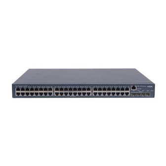
An S5120-SI switch provides 16, 24, or 48 downlink gigabit Ethernet interfaces. You can deploy the S5120-SI series at the access or distribution layer of a small- and medium-sized enterprise network. For example, you can use the series to provide gigabit to desktop connections or connecting data center server farms. - Page 12 Distribution Layer Switches Deploy the S5120-SI series at the distribution layer of a medium- and large-sized enterprise or campus network to provide high-performance and large-capacity switching service. Figure 3-1 An enterprise network Access Switches The S5120-SI series can serve as access switches to provide large access bandwidth and high port...
- Page 13 Figure 3-2 An enterprise network Core/Aggregation S9500/S7500E Access S5120-SI S5120-SI...
-
Page 14: Table Of Contents
What Is CLI? ···········································································································································1-1 Entering the CLI ······································································································································1-1 Entering CLI Through the Console Port ··························································································1-2 Entering CLI Through Telnet ···········································································································1-6 H3C Products CLI Descriptions ··············································································································1-7 Command Conventions ···················································································································1-7 CLI View Description ·······················································································································1-8 Command View Reference ·············································································································1-9 Tips on Using the CLI····························································································································1-14 Using the CLI Online Help·············································································································1-14... -
Page 15: Cli Configuration
CLI allows you to input a command containing more information at one time. On the H3C switch series, which deliver powerful functions, it is faster to perform configurations by using the CLI. The CLI of H3C switches is as shown in Figure 1-1. -
Page 16: Entering Cli Through The Console Port
Entering CLI Through the Console Port When you use the CLI of an H3C switch for the first time, you can log in to the switch and enter the CLI through the console port only. Follow these steps to log in to your H3C switch and enter the CLI through the console port: Use the console cable shipped with your switch to connect your PC to your switch. - Page 17 Figure 1-3 Connection description Then, the Connect To window as shown in Figure 1-4 appears. Select the serial port you want to use from the Connect using drop-down list, and then click OK. Figure 1-4 Specify the serial port used to establish the connection The COM1 Properties window as shown in Figure 1-5 appears.
- Page 18 Figure 1-5 Set the properties of the serial port The HyperTerminal window as shown in Figure 1-6 appears. Figure 1-6 The HyperTerminal window...
- Page 19 Select File > Properties on the HyperTerminal window, and the Switch Properties window appears. Select the Settings tab as shown in Figure 1-7, select VT100 from the Emulation drop-down list, and then click OK. Figure 1-7 Select the emulation terminal on the Switch Properties window Press Enter on the HyperTerminal window.
-
Page 20: Entering Cli Through Telnet
Telnet login as soon as possible, so that you can use a remote terminal to configure and manage your switch. Telnet login authentication methods In order to restrict the login to your switch, H3C provides three Telnet login authentication methods. Select a proper method according to your network conditions. Table 1-1 Telnet login authentication methods... -
Page 21: H3C Products Cli Descriptions
An H3C switch provides multiple VTY user interfaces. At one time, only one user can telnet to a VTY user interface. Because a remote terminal cannot select the VTY user interface through which it logs in to the switch, it is recommended that you configure all VTY user interfaces with the same authentication method. -
Page 22: Cli View Description
The argument(s) before the ampersand (&) sign can be entered 1 to n times. A line starting with the # sign is comments. H3C command lines are case insensitive. Take the clock datetime time date command as an example to understand the command meaning... -
Page 23: Command View Reference
Available in any view other than user view Command View Reference This section describes the commonly used function views of the H3C switch series and how to enter these views. The following describes the views in details. Unless otherwise noted, all examples start in system view. - Page 24 Login command views Command Description Command to enter Example view [Sysname] user-interface aux 0 user-interface aux After entering this view, [Sysname-ui-aux0] User interface you can configure user view [Sysname] user-interface vty 0 interface parameters. user-interface vty [Sysname-ui-vty0] After entering this view, [Sysname] cluster Cluster view you can configure...
- Page 25 Command Description Command to enter Example view Enter IGMP-Snooping [Sysname] igmp-snooping IGMP-Snoopin view to configure IGMP igmp-snooping g view snooping related [Sysname-igmp-snooping] parameters. Enable IGMP snooping globally, create a VLAN, and [Sysname] igmp-snooping enable IGMP [Sysname-igmp-snooping] quit snooping [Sysname] vlan 100 VLAN.
- Page 26 Command Description Command to enter Example view Enter priority mapping Priority [Sysname] qos map-table dot1p-dp table view and mapping table qos map-table configure mappings in [Sysname-maptbl-dot1p-dp] view this view. Create domain and enter its view. [Sysname] domain test ISP domain After entering this domain view...
- Page 27 Command Description Command to enter Example view Create certificate attribute group and enter its [Sysname] pki certificate attribute-group PKI certificate view. pki certificate test attribute group attribute-group After entering this view [Sysname-pki-cert-attribute-group-test] view, configure the PKI certificate attributes. Create certificate attribute-based access control...
-
Page 28: Tips On Using The Cli
Command Description Command to enter Example view Enter client <Sysname> ftp FTP client view view to configure [ftp] FTP parameters. Tips on Using the CLI Using the CLI Online Help In the CLI, you can type a question mark (?) to obtain detailed online help. See the following examples. Type ? in any view to display all commands available in this view and brief descriptions about these commands. -
Page 29: Command Line Error Information
Typing and Editing Commands Completing a partial command name The H3C switch series supports completing a partial command name for efficient input of commands. If in the current view, the character string you have typed can already uniquely identify a keyword, you do not need to type the complete keyword. -
Page 30: Displaying And Executing History Commands
Function Left arrow key or Ctrl+B The cursor moves one character space to the left. Right arrow key or Ctrl+F The cursor moves one character space to the right. If you press Tab after entering part of a keyword, the system automatically completes the keyword: If finding a unique match, the system substitutes the complete keyword for the incomplete one and displays it in the next line. -
Page 31: Undo Form Of A Command
current user interface (For more information about the history-command max-size command, see Login Configuration). Undo Form of a Command The undo form of a command typically restores the default, disables a function, or removes a configuration. Almost every configuration command has its undo form. For example, the info-center enable command is used to enable the information center, while the undo info-center enable command is used to disable the information center. - Page 32 For the support of the display commands for regular expressions, see the corresponding command reference. There are two ways to filter output information. Input the begin, exclude, or include keyword plus a regular expression in the display command to filter the output information. When the system displays the output information in multiple screens, use /, - or + plus a regular expression to filter subsequent output information.
- Page 33 Character Meaning Remarks For example, [16A] matches a string containing any character among 1, 6, and A; [1-36A] matches a string containing any character among 1, 2, 3, 6, and A (- is a hyphen). Matches a single character contained within the brackets. “]”...
-
Page 34: Anti-Interruption For Command Input
Configuration Commands. Saving Configurations Some commands in the CLI of H3C switches are one-time commands, such as display commands, which display specified information, and the reset commands, which clear specified information. These commands are executed one-time only and are not saved when the switch reboots. - Page 35 Table of Contents 1 Logging In to an Ethernet Switch ············································································································1-1 Logging In to an Ethernet Switch ············································································································1-1 Introduction to User Interface··················································································································1-1 Supported User Interfaces ··············································································································1-1 User Interface Number ····················································································································1-1 Common Login in to an Ethernet Switch·································································································1-2 2 Logging In Through the Console Port·····································································································2-1 Introduction ·············································································································································2-1 Setting Up the Connection to the Console Port ······················································································2-2 Console Port Login Configuration ···········································································································2-3...
- Page 36 Configuration Example····························································································································4-2 5 Logging In Through NMS··························································································································5-1 Introduction ·············································································································································5-1 Connection Establishment Using NMS ···································································································5-1 6 Specifying Source for Telnet Packets ·····································································································6-1 Introduction ·············································································································································6-1 Specifying Source IP address/Interface for Telnet Packets····································································6-1 Displaying the source IP address/Interface Specified for Telnet Packets ··············································6-2 7 Controlling Login Users····························································································································7-1 Introduction ·············································································································································7-1 Controlling Telnet Users ·························································································································7-1...
-
Page 37: Logging In To An Ethernet Switch
16 users VTY users. As the AUX port and the Console port of a H3C series switch are the same one, you will be in the AUX user interface if you log in through this port. User Interface Number Two kinds of user interface index exist: absolute user interface index and relative user interface index. -
Page 38: Common Login In To An Ethernet Switch
VTY user interfaces: Numbered after AUX user interfaces and increases in the step of 1 A relative user interface index can be obtained by appending a number to the identifier of a user interface type. It is generated by user interface type. The relative user interface indexes are as follows: AUX user interface: AUX 0 VTY user interfaces: VTY 0, VTY 1, VTY 2, and so on. - Page 39 To do… Use the command… Remarks Optional The default timeout time of a user interface is 10 minutes. With the timeout time being 10 minutes, the connection to a Set the timeout time for the idle-timeout minutes user interface is terminated if user interface [ seconds ] no operation is performed in the...
-
Page 40: Logging In Through The Console Port
Console Port Login Configuration with Authentication Mode Being Scheme The default system name of an H3C S5120-SI series Ethernet switch is H3C, that is, the command line prompt is H3C. All the following examples take H3C as the command line prompt. -
Page 41: Setting Up The Connection To The Console Port
Setting Up the Connection to the Console Port Connect the serial port of your PC/terminal to the Console port of the switch, as shown in Figure 2-1. Figure 2-1 Diagram for setting the connection to the Console port If you use a PC to connect to the Console port, launch a terminal emulation utility (such as Terminal in Windows XP/Windows 2000) and perform the configuration shown in Figure 2-2 through... -
Page 42: Console Port Login Configuration
Figure 2-4 Set port parameters terminal window Turn on the switch. The user will be prompted to press the Enter key if the switch successfully completes POST (power-on self test). The prompt (such as <H3C>) appears after the user presses the Enter key. -
Page 43: Console Port Login Configurations For Different Authentication Modes
Configuration Description Configure the command Optional user level available interface By default, commands of level 3 are available to the users logging in to the configuration users logging in to the AUX user interface. AUX user interface Optional Define a shortcut key for The default shortcut key combination for aborting aborting tasks tasks is <... -
Page 44: Console Port Login Configuration With Authentication Mode Being None
Authentication Console port login configuration Description mode AAA configuration Optional Specify to specifies whether perform local Local authentication is performed by to perform local authentication default. authentication or or RADIUS Refer to the AAA Configuration for RADIUS authentication details. authentication Required The user name and password of a local user are configured on the... - Page 45 To do… Use the command… Remarks Optional Set the check parity { even | mark | none | By default, the check mode of a mode odd | space } Console port is set to none, that is, no check bit. Optional Set the stop stopbits { 1 | 1.5 | 2 }...
-
Page 46: Configuration Example
Table 2-4 Determine the command level (A) Scenario Command level Authentication User type Command mode The user privilege level level Level 3 command not executed None Users logging in (authentication-mod through Determined The user privilege level level e none) Console ports level command already executed argument... -
Page 47: Console Port Login Configuration With Authentication Mode Being Password
# Specify commands of level 2 are available to the user logging in to the AUX user interface. [Sysname-ui-aux0] user privilege level 2 # Set the baud rate of the Console port to 19200 bps. [Sysname-ui-aux0] speed 19200 # Set the maximum number of lines the screen can contain to 30. [Sysname-ui-aux0] screen-length 30 # Set the maximum number of commands the history command buffer can store to 20. - Page 48 To do… Use the command… Remarks Optional Set the speed speed-value The default baud rate of an AUX port baud rate (also the Console port) is 9,600 bps. Optional Set the parity { even | mark | none check By default, the check mode of a Console | odd | space } Configure mode...
-
Page 49: Configuration Example
Note that if you configure to authenticate the users in the password mode, the command level available to users logging in to a switch depends on both the authentication-mode password and the user privilege level level command, as listed in the following table. Table 2-5 Determine the command level (B) Scenario Command level... -
Page 50: Console Port Login Configuration With Authentication Mode Being Scheme
[Sysname] user-interface aux 0 # Specify to authenticate the user logging in through the Console port using the local password. [Sysname-ui-aux0] authentication-mode password # Set the local password to 123456 (in plain text). [Sysname-ui-aux0] set authentication password simple 123456 # Specify commands of level 2 are available to the user logging in to the AUX user interface. [Sysname-ui-aux0] user privilege level 2 # Set the baud rate of the Console port to 19200 bps. - Page 51 To do… Use the command… Remarks Enter system view system-view — Enter Optional default ISP By default, the local AAA scheme is domain domain name domain applied. If you specify to apply the local view AAA scheme, you need to perform the configuration concerning local user as Specify the authentication...
-
Page 52: Configuration Example
To do… Use the command… Remarks Optional Define a shortcut key for starting terminal activation-key character By default, pressing Enter key starts the sessions terminal session. Optional Define a shortcut key for escape-key { default | The default shortcut key combination for aborting tasks character } aborting tasks is <... - Page 53 Network diagram Figure 2-7 Network diagram for AUX user interface configuration (with the authentication mode being scheme) Configuration procedure # Enter system view. <Sysname> system-view # Create a local user named guest and enter local user view. [Sysname] local-user guest # Set the authentication password to 123456 (in plain text).
-
Page 54: Logging In Through Telnet/Ssh
Logging In Through Telnet/SSH When logging in through Telnet, go to these sections for information you are interested in: Introduction Telnet Configuration with Authentication Mode Being None Telnet Configuration with Authentication Mode Being Password Telnet Configuration with Authentication Mode Being Scheme Telnet Connection Establishment Introduction You can telnet to a remote switch to manage and maintain the switch. -
Page 55: Telnet Connection Establishment
Telnet Connection Establishment Telnetting to a Switch from a Terminal You can telnet to a switch and then configure the switch if the interface of the management VLAN of the switch is assigned with an IP address. (By default, VLAN 1 is the management VLAN.) Following are procedures to establish a Telnet connection to a switch: Step 1: Log in to the switch through the Console port, enable the Telnet server function and assign an IP address to the management VLAN interface of the switch. -
Page 56: Telnetting To Another Switch From The Current Switch
Step 5: Enter the password when the Telnet window displays “Login authentication” and prompts for login password. The CLI prompt (such as <H3C>) appears if the password is correct. If all VTY user interfaces of the switch are in use, you will fail to establish the connection and receive the message that says “All user interfaces are used, please try later!”. -
Page 57: Common Configuration
Step 4: Enter the password. If the password is correct, the CLI prompt (such as <H3C>) appears. If all VTY user interfaces of the switch are in use, you will fail to establish the connection and receive the message that says “All user interfaces are used, please try later!”. -
Page 58: Telnet Configurations For Different Authentication Modes
The auto-execute command command may cause you unable to perform common configuration in the user interface, so use it with caution. Before executing the auto-execute command command and save your configuration, make sure you can log in to the switch in other modes and cancel the configuration. Telnet Configurations for Different Authentication Modes Table 3-3 lists Telnet configurations for different authentication modes. - Page 59 To do… Use the command… Remarks Enter system view system-view — Enter one or more VTY user user-interface vty first-number — interface views [ last-number ] Required Configure not to authenticate users logging in to VTY user authentication-mode none By default, VTY users are interfaces authenticated after logging in.
-
Page 60: Configuration Example
Note that if you configure not to authenticate the users, the command level available to users logging in to a switch depends on both the authentication-mode none command and the user privilege level level command, as listed in Table 3-4. Table 3-4 Determine the command level when users logging in to switches are not authenticated Scenario Command level... -
Page 61: Telnet Configuration With Authentication Mode Being Password
# Configure Telnet protocol is supported. [Sysname-ui-vty0] protocol inbound telnet # Set the maximum number of lines the screen can contain to 30. [Sysname-ui-vty0] screen-length 30 # Set the maximum number of commands the history command buffer can store to 20. [Sysname-ui-vty0] history-command max-size 20 # Set the timeout time to 6 minutes. -
Page 62: Configuration Example
To do… Use the command… Remarks Optional By default, the screen can contain up to 24 lines. Set the maximum number of screen-length screen-length You can use the screen-length lines the screen can contain 0 command to disable the function to display information in pages. -
Page 63: Telnet Configuration With Authentication Mode Being Scheme
Commands of level 2 are available to users logging in to VTY 0. Telnet protocol is supported. The screen can contain up to 30 lines. The history command buffer can contain up to 20 commands. The timeout time of VTY 0 is 6 minutes. Network diagram Figure 3-5 Network diagram for Telnet configuration (with the authentication mode being password) Configuration procedure... - Page 64 To do… Use the command… Remarks Enter system view system-view — Enter Optional default domain domain name By default, the local AAA scheme is domain view applied. If you specify to apply the local AAA scheme, you need to Configure authentication default perform the configuration concerning...
-
Page 65: Configuration Example
To do… Use the command… Remarks Optional Make terminal services shell Terminal services are available in all available use interfaces by default. Optional By default, the screen can contain up Set the maximum number screen-length to 24 lines. of lines the screen can screen-length You can use the screen-length 0 contain... -
Page 66: Logging In Through Ssh
The screen can contain up to 30 lines. The history command buffer can store up to 20 commands. The timeout time of VTY 0 is 6 minutes. Network diagram Figure 3-6 Network diagram for Telnet configuration (with the authentication mode being scheme) Configuration procedure # Enter system view, and enable the Telnet service. -
Page 67: Introduction
Management System Introduction An S5120-SI series switch has a Web server built in. You can log in to an S5120-SI series switch through a Web browser and manage and maintain the switch intuitively by interacting with the built-in Web server. -
Page 68: Displaying Web Users
To do… Use the command… Remarks Optional Specify the service types for service-type telnet By default, no service is the local user authorized to a user. Required Start the Web server ip http enable Execute this command in system view. Displaying Web Users After the above configurations, execute the display command in any view to display the information about Web users, and thus to verify the configuration effect. - Page 69 Step 4: Log in to the switch through IE. Launch IE on the Web-based network management terminal (your PC) and enter the IP address of the management VLAN interface of the switch (here it is http://10.153.17.82). (Make sure the route between the Web-based network management terminal and the switch is available.) Step 5: When the login interface (shown in Figure...
-
Page 70: Logging In Through Nms
Logging In Through NMS When logging in through NMS, go to these sections for information you are interested in: Introduction Connection Establishment Using NMS Introduction You can also log in to a switch through an NMS (network management station), and then configure and manage the switch through the agent module on the switch. -
Page 71: Specifying Source For Telnet Packets
Specifying Source for Telnet Packets When specifying source IP address/interface for Telnet packets, go to these sections for information you are interested in: Introduction Specifying Source IP address/Interface for Telnet Packets Displaying the source IP address/Interface Specified for Telnet Packets Introduction To improve security and make it easier to manage services, you can specify source IP addresses/interfaces for Telnet clients. -
Page 72: Displaying The Source Ip Address/Interface Specified For Telnet Packets
To do… Use the command… Remarks telnet client source { ip Optional Specify source IP ip-address | interface address/interface for Telnet By default, no source IP interface-type packets address/interface is specified. interface-number } The IP address specified must be a local IP address. When specifying the source interface for Telnet packets, make sure the interface already exists. -
Page 73: Controlling Login Users
Controlling Login Users When controlling login users, go to these sections for information you are interested in: Introduction Controlling Telnet Users Controlling Network Management Users by Source IP Addresses Introduction Multiple ways are available for controlling different types of login users, as listed in Table 7-1. -
Page 74: Controlling Telnet Users By Source And Destination Ip Addresses
To do… Use the command… Remarks number acl-number number Create a basic ACL or enter [ match-order { config | command, the config keyword basic ACL view auto } ] is specified by default. rule [ rule-id ] { permit | deny } source sour-addr Define rules for the ACL... -
Page 75: Controlling Telnet Users By Source Mac Addresses
Controlling Telnet Users by Source MAC Addresses This configuration needs to be implemented by Layer 2 ACL; a Layer 2 ACL ranges from 4000 to 4999. For the definition of ACL, refer to ACL Configuration. Follow these steps to control Telnet users by source MAC addresses: To do…... -
Page 76: Controlling Network Management Users By Source Ip Addresses
[Sysname-ui-vty0-4] acl 2000 inbound Controlling Network Management Users by Source IP Addresses You can manage a H3C S5120-SI series Ethernet switch through network management software. Network management users can access switches through SNMP. You need to perform the following two operations to control network management users by source IP addresses. -
Page 77: Configuration Example
To do… Use the command… Remarks number acl-number number Create a basic ACL or enter [ match-order { config | command, the config keyword basic ACL view auto } ] is specified by default. rule [ rule-id ] { permit | deny } source sour-addr Define rules for the ACL... -
Page 78: Controlling Web Users By Source Ip Addresses
# Apply the ACL to only permit SNMP users sourced from the IP addresses of 10.110.100.52 and 10.110.100.46 to access the switch. [Sysname] snmp-agent community read h3c acl 2000 [Sysname] snmp-agent group v2c h3cgroup acl 2000 [Sysname] snmp-agent usm-user v2c h3cuser h3cgroup acl 2000... -
Page 79: Forcing Online Web Users Offline
To do… Use the command… Remarks Required Create a basic ACL or enter acl number acl-number [ match-order The config keyword is basic ACL view { config | auto } ] specified by default. rule [ rule-id ] { permit | deny } [ source { sour-addr sour-wildcard | any } | Define rules for the ACL Required... - Page 80 [Sysname] ip http acl 2030...
- Page 81 Table of Contents 1 Ethernet Port Configuration ·····················································································································1-1 Basic Ethernet Port Configuration···········································································································1-1 Configuring an Auto-negotiation Transmission Rate ··············································································1-2 Configuring Flow Control on an Ethernet Port ························································································1-3 Perfoming Loopback Testing on an Ethernet Port··················································································1-3 Enabling Auto Power Down on an Ethernet Port····················································································1-5 Configuring a Port Group ························································································································1-5 Configuring Traffic Storm Protection·······································································································1-6 Configuring Storm Suppression ······································································································1-6...
-
Page 82: Ethernet Port Configuration
Ethernet Port Configuration When configuring Ethernet ports, go to these sections for information you are interested in: Basic Ethernet Port Configuration Configuring an Auto-negotiation Transmission Rate Configuring Flow Control on an Ethernet Port Perfoming Loopback Testing on an Ethernet Port Enabling Auto Power Down on an Ethernet Port Configuring a Port Group Configuring Traffic Storm Protection... -
Page 83: Configuring An Auto-Negotiation Transmission Rate
To do… Use the command… Remarks Optional auto by default. Set the duplex mode duplex { auto | full | half } The optical interface of a SFP port does not support the half keyword. Optional The optical interface of a SFP port does not support the 10 or 100 Set the transmission rate speed { 10 | 100 | 1000 | auto }... -
Page 84: Configuring Flow Control On An Ethernet Port
To do… Use the command… Remarks Enter system view system-view — interface interface-type Enter Ethernet port view — interface-number Configure the auto-negotiation speed auto [ 10 | 100 | 1000 ] * Optional transmission rate range This function is available for auto-negotiation-capable Gigabit Layer-2 Ethernet electrical ports only. - Page 85 Figure 1-2 Internal loopback testing External loopback testing, which tests the hardware of Ethernet ports. As shown in Figure 1-3, external loopback testing is performed on Port 1. To perform external loopback testing on an Ethernet port, insert a loopback plug into the port. During the external loopback testing, the port sends out a certain number of test packets, which are looped over the plug and back to the port.
-
Page 86: Enabling Auto Power Down On An Ethernet Port
Enabling Auto Power Down on an Ethernet Port When an Ethernet port does not receive any packet for a certain period of time, it automatically enters the power save mode and resumes its normal state upon the arrival of a packet. Follow these steps to enable auto power down on an Ethernet port: To do…... -
Page 87: Configuring Traffic Storm Protection
Configuring Traffic Storm Protection A traffic storm occurs when a large amount of broadcast, multicast, or unicast packets congest a network. The S5120-SI switches provide two storm protection approaches: Storm suppression, which enables you to limit the size of monitored traffic passing through an Ethernet port by setting a traffic threshold. -
Page 88: Configuring The Storm Constrain Function On An Ethernet Port
As for an Ethernet port belongs to a port group, if you set a storm suppression ratio for the interface in both Ethernet port view and port group view, the one configured the last takes effect. Configuring the Storm Constrain Function on an Ethernet Port The storm constrain function suppresses packet storms in an Ethernet. -
Page 89: Setting The Interval For Collecting Ethernet Port Statistics
To do… Use the command… Remarks Optional Specify to send trap messages By default, the system sends when the traffic detected trap messages when the traffic exceeds the upper threshold or detected exceeds the upper storm-constrain enable trap drops down below the lower threshold or drops down below threshold from a point higher the lower threshold from a point... -
Page 90: Enabling Forwarding Of Jumbo Frames
Enabling Forwarding of Jumbo Frames Due to tremendous amount of traffic occurring on an Ethernet port, it is likely that some frames greater than the standard Ethernet frame size are received. Such frames (called jumbo frames) will be dropped. With forwarding of jumbo frames enabled, the system does not drop all the jumbo frames. Instead, it continues to process jumbo frames with a size greater than the standard Ethernet frame size and yet within the specified parameter range. -
Page 91: Configuring The Mdi Mode For An Ethernet Port
To do… Use the command… Remarks Optional Configure the interval for port loopback-detection loopback detection interval-time time 30 seconds by default interface interface-type Enter Ethernet port view — interface-number Required Enable loopback detection on a loopback-detection enable port Disabled by default Enable loopback detection Optional loopback-detection control... -
Page 92: Enabling Bridging On An Ethernet Port
Normally, the auto mode is recommended. The other two modes are useful only when the device cannot determine the cable type. When straight-through cables are used, the local MDI mode must be different from the remote MDI mode. When crossover cables are used, the local MDI mode must be the same as the remote MDI mode, or the MDI mode of at least one end must be set to auto. -
Page 93: Displaying And Maintaining An Ethernet Port
To do… Use the command… Remarks Enter system view system-view — interface interface-type Enter Ethernet port view — interface-number Test the cable connected to the Required virtual-cable-test Ethernet port once Displaying and Maintaining an Ethernet Port To do… Use the command… Remarks Display the current state of an display interface [ interface-type... - Page 94 Table of Contents 1 Loopback Interface and Null Interface Configuration············································································1-1 Loopback Interface··································································································································1-1 Introduction to Loopback Interface ··································································································1-1 Configuring a Loopback Interface ···································································································1-1 Null Interface ···········································································································································1-2 Introduction to Null Interface ···········································································································1-2 Configuring Null 0 Interface·············································································································1-2 Displaying and Maintaining Loopback and Null Interfaces ·····································································1-3...
-
Page 95: Loopback Interface
Loopback Interface and Null Interface Configuration When configuring loopback interfaces and null interfaces, go to these sections for information you are interested in: Loopback Interface Null Interface Displaying and Maintaining Loopback and Null Interfaces Loopback Interface Introduction to Loopback Interface A loopback interface is a software-only virtual interface. -
Page 96: Null Interface
To do… Use the command… Remarks Enter system view — system-view Create a Loopback interface interface loopback and enter Loopback interface — interface-number view Optional Set a description for the By default, the description of an description text loopback interface interface is the interface name followed by the “Interface”... -
Page 97: Displaying And Maintaining Loopback And Null Interfaces
To do… Use the command… Remarks Enter system view — system-view Required The Null 0 interface is the default null Enter null interface view interface null 0 interface on your device. It cannot be manually created or removed. Optional Set a description for the By default, the description of an interface description text null interface... - Page 98 Table of Contents 1 Ethernet Link Aggregation Configuration·······························································································1-1 Overview ·················································································································································1-1 Basic Concepts································································································································1-1 Aggregating Links in Static Mode····································································································1-5 Aggregating Links in Dynamic Mode·······························································································1-6 Ethernet Link Aggregation Configuration Task List ················································································1-7 Configuring an Aggregation Group ·········································································································1-8 Configuration Guidelines ·················································································································1-8 Configuring a Static Aggregation Group··························································································1-8 Configuring a Dynamic Aggregation Group·····················································································1-9 Configuring an Aggregate Interface ······································································································1-10 Configuring the Description of an Aggregate Interface ·································································1-10...
-
Page 99: Ethernet Link Aggregation Configuration
Ethernet Link Aggregation Configuration This chapter includes these sections: Overview Ethernet Link Aggregation Configuration Task List Configuring an Aggregation Group Configuring an Aggregate Interface Displaying and Maintaining Ethernet Link Aggregation Ethernet Link Aggregation Configuration Examples Overview Ethernet link aggregation, most often simply called link aggregation, aggregates multiple physical Ethernet links into one logical link to increase link bandwidth beyond the limits of any one single link. - Page 100 Current device only supports Layer 2 aggregation group and Layer 2 aggregate interface. The rate of an aggregate interface equals the total rate of its member ports in selected state and its duplex mode is the same as that of the selected member ports. For more information about the states of member ports in an aggregation group, refer to Aggregation states of member ports in an aggregation...
- Page 101 Extended LACP This is how the LACP multi-active detection (MAD) mechanism of the functions Intelligent Resilient Framework (IRF) feature is implemented. Switches of the S5120-SI series that support extended LACP functions can be used as intermediate devices in LACP MAD implementation...
- Page 102 For details about IRF, member devices, intermediate devices, and the LACP MAD mechanism, see the operation manuals of IRF-supported devices. LACP priorities There are two types of LACP priorities: system LACP priority and port LACP priority, as described in Table 1-3.
-
Page 103: Aggregating Links In Static Mode
Aggregating Links in Static Mode LACP is disabled on the member ports in a static aggregation group. The aggregation state of the member ports must be maintained manually. Static link aggregation comprises: Selecting a reference port Setting the aggregation state of each member port Selecting a reference port The system selects a reference port from the member ports that are in the up state and have the same class-two configurations as the aggregate interface. -
Page 104: Aggregating Links In Dynamic Mode
Because any port attribute or class-two configuration change on a member port may cause the aggregation state of the port and other member ports to change and thus affect services, it is recommended that you do that with caution. A port that joins the static aggregation group after the selected port limit has been reached will not be placed in the selected state even if it should be in normal cases. -
Page 105: Ethernet Link Aggregation Configuration Task List
Figure 1-3 Set the state of a member port in a dynamic aggregation group Set the aggregation state of a member port Is there any hardware restriction? Is the port up? Port attribute/class-two configurations same as the reference port? Port attribute/class-two configurations same as the peer port of the reference port? More candidate ports than... -
Page 106: Configuring An Aggregation Group
Task Remarks Configuring an Configuring a Static Aggregation Group Aggregation Select either task Configuring a Dynamic Aggregation Group Group Configuring the Description of an Aggregate Interface Optional Configuring an Enabling Link State Trapping for an Aggregate Aggregate Optional Interface Interface Shutting Down an Aggregate Interface Optional Configuring an Aggregation Group... -
Page 107: Configuring A Dynamic Aggregation Group
To do... Use the command... Remarks Required When you create a Layer 2 Create a Layer 2 aggregate interface bridge-aggregation aggregate interface, the system interface and enter the Layer 2 interface-number automatically creates a Layer 2 aggregate interface view static aggregation group numbered the same. -
Page 108: Configuring An Aggregate Interface
To do... Use the command... Remarks assign multiple Layer 2 Assign the Ethernet interface to port link-aggregation group Ethernet interfaces to the the aggregation group number aggregation group. Optional By default, the LACP priority of a port is 32768. Assign the port a LACP priority lacp port-priority port-priority Changing the LACP priority of a port may affect the aggregation... -
Page 109: Shutting Down An Aggregate Interface
To do... Use the command... Remarks Optional Enable the trap function snmp-agent trap enable By default, link state trapping globally [ standard [ linkdown | linkup ] * ] is enabled globally and on all interfaces. Enter aggregate interface interface bridge-aggregation —... -
Page 110: Ethernet Link Aggregation Configuration Examples
To do... Use the command... Remarks reset counters interface Clear statistics for a specific or [ bridge-aggregation } Available in user view all aggregate interfaces [ interface-number ] ] Ethernet Link Aggregation Configuration Examples In an aggregation group, only ports that have the same port attributes and class-two configurations (see Configuration classes section) as the reference port (see the Reference port... - Page 111 <DeviceA> system-view [DeviceA] vlan 10 [DeviceA-vlan10] port GigabitEthernet 1/0/4 [DeviceA-vlan10] quit # Create VLAN 20, and assign port GigabitEthernet 1/0/5 to VLAN 20. [DeviceA] vlan 20 [DeviceA-vlan20] port GigabitEthernet 1/0/5 [DeviceA-vlan20] quit # Create Layer 2 aggregate interface 1. [DeviceA] interface bridge-aggregation 1 [DeviceA-Bridge-Aggregation1] quit # Assign ports GigabitEthernet 1/0/1 through GigabitEthernet 1/0/3 to link aggregation group 1 [DeviceA] interface GigabitEthernet 1/0/1...
-
Page 112: Dynamic Aggregation Configuration Example
BAGG -- Bridge-Aggregation, RAGG -- Route-Aggregation Aggregation Mode: S -- Static, D -- Dynamic Loadsharing Type: Shar -- Loadsharing, NonS -- Non-Loadsharing Actor System ID: 0x8000, 000f-e2ff-0001 Partner ID Select Unselect Share Interface Mode Ports Ports Type ------------------------------------------------------------------------------- BAGG1 none Shar The output shows that link aggregation group 1 is a load sharing Layer 2 static aggregation group and it contains three selected ports. - Page 113 [DeviceA-vlan20] quit # Create Layer 2 aggregate interface 1, and configure the link aggregation mode as dynamic. [DeviceA] interface bridge-aggregation 1 [DeviceA-Bridge-Aggregation1] link-aggregation mode dynamic [DeviceA-Bridge-Aggregation1] quit # Assign ports GigabitEthernet 1/0/1 through GigabitEthernet 1/0/3 to link aggregation group 1. [DeviceA] interface GigabitEthernet 1/0/1 [DeviceA-GigabitEthernet1/0/1] port link-aggregation group 1 [DeviceA-GigabitEthernet1/0/1] quit...
- Page 114 ------------------------------------------------------------------------------- BAGG1 0x8000, 000f-e2ff-0002 Shar The output shows that link aggregation group 1 is a load sharing Layer 2 dynamic aggregation group and it contains three selected ports. 1-16...
- Page 115 Table of Contents 1 Port Isolation Configuration ·····················································································································1-1 Introduction to Port Isolation ···················································································································1-1 Configuring an Isolation Group for a Multiple-Isolation-Group Device ···················································1-1 Adding a Port to an Isolation Group ································································································1-1 Displaying and Maintaining Isolation Groups··························································································1-2 Port Isolation Configuration Example······································································································1-2...
-
Page 116: Port Isolation Configuration
Port Isolation Configuration When configuring port isolation, go to these sections for information you are interested in: Introduction to Port Isolation Configuring an Isolation Group for a Multiple-Isolation-Group Device Displaying and Maintaining Isolation Groups Port Isolation Configuration Example Introduction to Port Isolation Usually, Layer 2 traffic isolation is achieved by assigning ports to different VLANs. -
Page 117: Displaying And Maintaining Isolation Groups
To do… Use the command… Remarks Required Add the port/ports to an port-isolate enable group isolation group as an No ports are added to an group-number isolated port/isolated ports isolation group by default. Displaying and Maintaining Isolation Groups To do… Use the command…... - Page 118 [Device-GigabitEthernet1/0/1] port-isolate enable group 2 [Device-GigabitEthernet1/0/1] quit [Device] interface gigabitethernet 1/0/2 [Device-GigabitEthernet1/0/2] port-isolate enable group 2 [Device-GigabitEthernet1/0/2] quit [Device] interface gigabitethernet 1/0/3 [Device-GigabitEthernet1/0/3] port-isolate enable group 2 # Display information of isolation group 2. <Device> display port-isolate group 2 Port-isolate group information: Uplink port support: YES Group ID: 2 Group members:...
- Page 119 Table of Contents 1 Port Mirroring Configuration ····················································································································1-1 Introduction to Port Mirroring ··················································································································1-1 Classification of Port Mirroring ········································································································1-1 Implementing Port Mirroring ············································································································1-1 Configuring Local Port Mirroring ·············································································································1-2 Displaying and Maintaining Port Mirroring ······························································································1-3 Port Mirroring Configuration Examples ···································································································1-3 Local Port Mirroring Configuration Example····················································································1-3...
-
Page 120: Port Mirroring Configuration
Implementing Port Mirroring In local port mirroring, all packets (including protocol packets and data packets) passing through a port can be mirrored. Local port mirroring is implemented through a local mirroring group. An S5120-SI series switch supports one local mirroring group. -
Page 121: Configuring Local Port Mirroring
As shown in Figure 1-1, packets on the mirroring port are mirrored to the monitor port for the data monitoring device to analyze. Figure 1-1 Local port mirroring implementation Configuring Local Port Mirroring Configuring local port mirroring is to configure local mirroring groups. A local mirroring group comprises one or multiple mirroring ports and one monitor port. -
Page 122: Displaying And Maintaining Port Mirroring
A local mirroring group takes effect only after you configure a monitor port and mirroring ports for it. To ensure the smooth operation of your device, do not enable STP, MSTP, or RSTP on the monitor port. You are recommended to use a monitor port only for port mirroring. This is to ensure that the data monitoring device receives and analyzes only the mirrored traffic rather than a mix of mirrored traffic and normally forwarded traffic. - Page 123 Configuration procedure Configuration scheme 1 # Create a local mirroring group. <DeviceC> system-view [DeviceC] mirroring-group 1 local # Configure ports GigabitEthernet 1/0/1 and GigabitEthernet 1/0/2 as mirroring ports and port GigabitEthernet 1/0/3 as the monitor port in the mirroring group. [DeviceC] mirroring-group 1 mirroring-port gigabitethernet 1/0/1 gigabitethernet 1/0/2 both [DeviceC] mirroring-group 1 monitor-port gigabitethernet 1/0/3 # Display the configuration of all mirroring groups.
- Page 124 Table of Contents 1 LLDP Configuration···································································································································1-1 Overview ·················································································································································1-1 Background ·····································································································································1-1 Basic Concepts································································································································1-1 How LLDP Works ····························································································································1-5 Protocols and Standards ·················································································································1-6 LLDP Configuration Task List ·················································································································1-6 Performing Basic LLDP Configuration ····································································································1-7 Enabling LLDP·································································································································1-7 Setting the LLDP Operating Mode ··································································································1-7 Setting the LLDP Re-Initialization Delay ·························································································1-8 Enabling LLDP Polling·····················································································································1-8 Configuring the Advertisable TLVs··································································································1-8 Configuring the Management Address and Its Encoding Format ···················································1-9...
-
Page 125: Lldp Configuration
LLDP Configuration This chapter includes these sections: Overview LLDP Configuration Task List Performing Basic LLDP Configuration Configuring CDP Compatibility Configuring LLDP Trapping Displaying and Maintaining LLDP LLDP Configuration Examples Overview Background In a heterogeneous network, it is important that different types of network devices from different vendors can discover one another and exchange configuration for interoperability and management sake. - Page 126 Figure 1-1 Ethernet II-encapsulated LLDPDU format The fields in the frame are described in Table 1-1: Table 1-1 Description of the fields in an Ethernet II-encapsulated LLDPDU Field Description The MAC address to which the LLDPDU is advertised. It is fixed to Destination MAC address 0x0180-C200-000E, a multicast MAC address.
- Page 127 Field Description The MAC address of the sending port. If the port does not have a MAC Source MAC address address, the MAC address of the sending bridge is used. The SNAP type for the upper layer protocol. It is Type 0xAAAA-0300-0000-88CC for LLDP.
- Page 128 Indicates protocols supported on the port. An LLDPDU can carry Protocol Identity multiple different TLVs of this type. Currently, H3C devices only support receiving protocol identity TLVs. IEEE 802.3 organizationally specific TLVs Table 1-5 IEEE 802.3 organizationally specific TLVs Type...
-
Page 129: How Lldp Works
LLDP-MED TLVs LLDP-MED TLVs provide multiple advanced applications for voice over IP (VoIP), such as basic configuration, network policy configuration, and address and directory management. LLDP-MED TLVs provide a cost-effective and easy-to-use solution for deploying voice devices in Ethernet. LLDP-MED TLVs are shown in Table 1-6:... -
Page 130: Protocols And Standards
can configure a re-initialization delay. With this delay configured, a port must wait for the specified interval before it can initialize LLDP after the LLDP operating mode changes. Transmitting LLDPDUs An LLDP-enabled port operating in TxRx mode or Tx mode sends LLDPDUs to its directly connected devices both periodically and when the local configuration changes. -
Page 131: Performing Basic Lldp Configuration
LLDP-related configurations made in Layer 2 Ethernet port view take effect only on the current port, and those made in port group view take effect on all ports in the current port group. Performing Basic LLDP Configuration Enabling LLDP To make LLDP take effect on certain ports, you must enable LLDP both globally and on these ports. Follow these steps to enable LLDP: To do…... -
Page 132: Setting The Lldp Re-Initialization Delay
Setting the LLDP Re-Initialization Delay When LLDP operating mode changes on a port, the port initializes the protocol state machines after a certain delay. By adjusting the LLDP re-initialization delay, you can avoid frequent initializations caused by frequent LLDP operating mode changes on a port. Follow these steps to set the LLDP re-initialization delay for ports: To do…... -
Page 133: Configuring The Management Address And Its Encoding Format
To do… Use the command… Remarks lldp tlv-enable { basic-tlv { all | port-description | system-capability | system-description | system-name } | Optional dot1-tlv { all | port-vlan-id | protocol-vlan-id By default, all types of [ vlan-id ] | vlan-name [ vlan-id ] } | dot3-tlv LLDP TLVs except Configure the advertisable { all | link-aggregation | mac-physic |... -
Page 134: Setting An Encapsulation Format For Lldpdus
By setting the TTL multiplier, you can configure the TTL of locally sent LLDPDUs, which determines how long information about the local device can be saved on a neighbor device. The TTL is expressed as follows: TTL = Min (65535, (TTL multiplier × LLDPDU transmit interval)) As the expression shows, the TTL can be up to 65535 seconds. -
Page 135: Configuring Cdp Compatibility
To do… Use the command… Remarks Enter Layer 2 interface interface-type Ethernet port Enter Ethernet interface-number Required view port view or port Use either command group view Enter port port-group manual port-group-name group view Required Set the encapsulation format for Ethernet II lldp encapsulation snap LLDPDUs to SNAP... -
Page 136: Configuring Lldp Trapping
Disable: The CDP packets can neither be transmitted nor be received. To make CDP-compatible LLDP take effect on certain ports, first enable CDP-compatible LLDP globally, and then configure CDP-compatible LLDP to operate in TxRx mode. Follow these steps to enable LLDP to be compatible with CDP: To do…... -
Page 137: Displaying And Maintaining Lldp
Displaying and Maintaining LLDP To do… Use the command… Remarks Display the global LLDP display lldp local-information [ global | information or the information interface interface-type Available in any view contained in the LLDP TLVs to interface-number ] be sent through a port display lldp neighbor-information Display the information [ brief | interface interface-type... - Page 138 # Enable LLDP on GigabitEthernet 1/0/1 and GigabitEthernet 1/0/2 (you can skip this step because LLDP is enabled on ports by default), and set the LLDP operating mode to Rx. [SwitchA] interface gigabitethernet 1/0/1 [SwitchA-GigabitEthernet1/0/1] lldp enable [SwitchA-GigabitEthernet1/0/1] lldp admin-status rx [SwitchA-GigabitEthernet1/0/1] quit [SwitchA] interface gigabitethernet 1/0/2 [SwitchA-GigabitEthernet1/0/2] lldp enable...
- Page 139 Port 2 [GigabitEthernet1/0/2]: Port status of LLDP : Enable Admin status : Rx_Only Trap flag : No Polling interval : 0s Number of neighbors: Number of MED neighbors Number of CDP neighbors Number of sent optional TLV Number of received unknown TLV : 3 As the sample output shows, GigabitEthernet 1/0/1 of Switch A connects to a MED device, and GigabitEthernet 1/0/2 of Switch A connects to a non-MED device.
-
Page 140: Cdp-Compatible Lldp Configuration Example
Number of MED neighbors Number of CDP neighbors Number of sent optional TLV Number of received unknown TLV As the sample output shows, GigabitEthernet 1/0/2 of Switch A does not connect to any neighboring devices. CDP-Compatible LLDP Configuration Example Network requirements As shown in Figure 1-5:... - Page 141 [SwitchA] interface gigabitethernet 1/0/1 [SwitchA-GigabitEthernet1/0/1] lldp enable [SwitchA-GigabitEthernet1/0/1] lldp admin-status txrx [SwitchA-GigabitEthernet1/0/1] lldp compliance admin-status cdp txrx [SwitchA-GigabitEthernet1/0/1] quit [SwitchA] interface gigabitethernet 1/0/2 [SwitchA-GigabitEthernet1/0/2] lldp enable [SwitchA-GigabitEthernet1/0/2] lldp admin-status txrx [SwitchA-GigabitEthernet1/0/2] lldp compliance admin-status cdp txrx [SwitchA-GigabitEthernet1/0/2] quit Verify the configuration # Display the neighbor information on Switch A.
- Page 142 Table of Contents 1 VLAN Configuration ··································································································································1-1 Introduction to VLAN ·······························································································································1-1 VLAN Overview ·······························································································································1-1 VLAN Fundamentals ·······················································································································1-2 Types of VLAN ································································································································1-3 Configuring Basic VLAN Settings ···········································································································1-3 Configuring Basic Settings of a VLAN Interface ·····················································································1-4 Port-Based VLAN Configuration ·············································································································1-5 Introduction to Port-Based VLAN ····································································································1-5 Assigning an Access Port to a VLAN ······························································································1-6 Assigning a Trunk Port to a VLAN···································································································1-7 Assigning a Hybrid Port to a VLAN ·································································································1-8...
-
Page 143: Vlan Configuration
VLAN Configuration When configuring VLAN, go to these sections for information you are interested in: Introduction to VLAN Configuring Basic VLAN Settings Configuring Basic Settings of a VLAN Interface Port-Based VLAN Configuration Displaying and Maintaining VLAN VLAN Configuration Example Introduction to VLAN VLAN Overview Ethernet is a network technology based on the Carrier Sense Multiple Access/Collision Detect (CSMA/CD) mechanism. -
Page 144: Vlan Fundamentals
Improving LAN security. By assigning user groups to different VLANs, you can isolate them at Layer 2. To enable communication between VLANs, routers or Layer 3 switches are required. Flexible virtual workgroup creation. As users from the same workgroup can be assigned to the same VLAN regardless of their physical locations, network construction and maintenance is much easier and more flexible. -
Page 145: Types Of Vlan
The Ethernet II encapsulation format is used here. Besides the Ethernet II encapsulation format, other encapsulation formats, including 802.2 LLC, 802.2 SNAP, and 802.3 raw, are also supported by Ethernet. The VLAN tag fields are also added to frames encapsulated in these formats for VLAN identification. -
Page 146: Configuring Basic Settings Of A Vlan Interface
As the default VLAN, VLAN 1 cannot be created or removed. You cannot manually create or remove VLANs reserved for special purposes. Dynamic VLANs cannot be removed with the undo vlan command. A VLAN with a QoS policy applied cannot be removed. Configuring Basic Settings of a VLAN Interface For hosts of different VLANs to communicate, you must use a router or Layer 3 switch to perform layer 3 forwarding. -
Page 147: Port-Based Vlan Configuration
Port-Based VLAN Configuration Introduction to Port-Based VLAN Port-based VLANs group VLAN members by port. A port forwards traffic for a VLAN only after it is assigned to the VLAN. Port link type You can configure the link type of a port as access, trunk, or hybrid. The three link types use different VLAN tag handling methods. -
Page 148: Assigning An Access Port To A Vlan
Actions (in the inbound direction) Actions (in the outbound Port type direction) Untagged frame Tagged frame Receive the frame if its VLAN ID is the same as the default VLAN ID. Tag the frame with the Remove the default VLAN Access Drop the frame if its default VLAN tag. -
Page 149: Assigning A Trunk Port To A Vlan
Follow these steps to assign an access port (in interface view) or multiple access ports (in port group view) to a VLAN: To do… Use the command… Remarks Enter system view system-view — Enter Ethernet Required interface interface-type interface view interface-number Use either command. -
Page 150: Assigning A Hybrid Port To A Vlan
To do… Use the command… Remarks Enter Required interface interface-type Ethernet Use either command. interface-number interface view In Ethernet interface view, the subsequent configurations Enter Layer-2 interface bridge-aggregation apply to the current port. aggregate interface-number interface view port group view, Enter subsequent configurations... -
Page 151: Displaying And Maintaining Vlan
To do… Use the command… Remarks view or port Use either command. Enter Layer-2 interface group view aggregate bridge-aggregation In Ethernet interface view, the interface view interface-number subsequent configurations apply to the current port. port group view, subsequent configurations apply to all ports in the port group. -
Page 152: Vlan Configuration Example
To do... Use the command… Remarks interface-number VLAN Configuration Example Network requirements Device A connects to Device B through a trunk port GigabitEthernet 1/0/1; The default VLAN ID of GigabitEthernet 1/0/1 is 100; GigabitEthernet 1/0/1 allows packets from VLAN 2, VLAN 6 through VLAN 50, and VLAN 100 to pass through. - Page 153 Verification Verifying the configuration on Device A is similar to that of Device B. So only Device A is taken for example here. # Display the information about GigabitEthernet 1/0/1 of Device A to verify the above configurations. <DeviceA> display interface gigabitethernet 1/0/1 GigabitEthernet1/0/1 current state: UP IP Packet Frame Type: PKTFMT_ETHNT_2, Hardware Address: 0000-5600-0000 Description: GigabitEthernet1/0/1 Interface...
-
Page 154: Voice Vlan Configuration
Voice VLAN Configuration When configuring a voice VLAN, go to these sections for information you are interested in: Overview Configuring a Voice VLAN Displaying and Maintaining Voice VLAN Voice VLAN Configuration Overview As voice communication technologies grow more mature, voice devices are more and more widely deployed, especially on broadband networks, where voice traffic and data traffic often co-exist. -
Page 155: Voice Vlan Assignment Modes
00e0-bb00-0000 3Com phone In general, as the first 24 bits of a MAC address (in binary format), an OUI address is a globally unique identifier assigned to a vendor by IEEE. OUI addresses mentioned in this document, however, are different from those in common sense. OUI addresses in this document are used by the system to determine whether a received packet is a voice packet. - Page 156 Figure 2-2 Only IP phones access the network Both modes forward tagged packets according to their tags. The following tables list the required configurations on ports of different link types in order for these ports to support tagged or untagged voice traffic sent from IP phones when different voice VLAN assignment modes are configured.
-
Page 157: Security Mode And Normal Mode Of Voice Vlans
Table 2-3 Required configurations on ports of different links types in order for the ports to support tagged voice traffic Voice VLAN Support for Port link type assignment untagged voice Configuration requirements mode traffic Automatic — Access Configure the default VLAN of the port as Manual the voice VLAN. -
Page 158: Configuring A Voice Vlan
the port forwards all received untagged packets in the voice VLAN. In normal mode, the voice VLANs are vulnerable to traffic attacks. Vicious users can forge a large amount of voice packets and send them to voice VLAN-enabled ports to consume the voice VLAN bandwidth, affecting normal voice communication. -
Page 159: Setting A Port To Operate In Automatic Voice Vlan Assignment Mode
Setting a Port to Operate in Automatic Voice VLAN Assignment Mode Follow these steps to set a port to operate in automatic voice VLAN assignment mode: To do... Use the command... Remarks Enter system view system-view — Optional 1440 minutes by default. The voice VLAN aging time Set the voice VLAN aging time voice vlan aging minutes... -
Page 160: Displaying And Maintaining Voice Vlan
To do... Use the command... Remarks Optional By default, each voice VLAN voice vlan mac-address oui Add a recognizable OUI has default OUI addresses mask oui-mask [ description address configured. Refer to Table 2-1 text ] for the default OUI addresses of different vendors. -
Page 161: Voice Vlan Configuration Examples
Voice VLAN Configuration Examples Automatic Voice VLAN Mode Configuration Example Network requirements As shown in Figure 2-3, The MAC address of IP phone A is 0011-1100-0001. The phone connects to a downstream device named PC A whose MAC address is 0022-1100-0002 and to GigabitEthernet 1/0/1 on an upstream device named Device A. -
Page 162: Manual Voice Vlan Assignment Mode Configuration Example
# Configure the allowed OUI addresses as MAC addresses prefixed by 0011-2200-0000. In this way, Device A identifies packets whose MAC addresses match any of the configured OUI addresses as voice packets. [DeviceA] voice vlan mac-address 0011-2200-0001 mask ffff-ff00-0000 description IP phone B # Configure GigabitEthernet 1/0/2 to operate in automatic voice VLAN assignment mode. - Page 163 Configure GigabitEthernet 1/0/1 to operate in manual voice VLAN assignment mode. Configure GigabitEthernet 1/0/1 to allow voice traffic with an OUI address of 0011-2200-0000, a mask of ffff-ff00-0000, and a description string test to be forwarded through the voice VLAN. Figure 2-4 Network diagram for manual voice VLAN assignment mode configuration Configuration procedure # Configure the voice VLAN to operate in security mode.
- Page 164 0001-e300-0000 ffff-ff00-0000 Siemens phone 0003-6b00-0000 ffff-ff00-0000 Cisco phone 0004-0d00-0000 ffff-ff00-0000 Avaya phone 0011-2200-0000 ffff-ff00-0000 test 00d0-1e00-0000 ffff-ff00-0000 Pingtel phone 0060-b900-0000 ffff-ff00-0000 Philips/NEC phone 00e0-7500-0000 ffff-ff00-0000 Polycom phone 00e0-bb00-0000 ffff-ff00-0000 3com phone # Display the current voice VLAN state. <DeviceA> display voice vlan state Maximum of Voice VLANs: 1 Current Voice VLANs: 1 Voice VLAN security mode: Security...
- Page 165 Table of Contents 1 MSTP Configuration ··································································································································1-1 Overview ·················································································································································1-1 Introduction to STP ·································································································································1-1 Why STP ·········································································································································1-1 Protocol Packets of STP··················································································································1-1 Basic Concepts in STP····················································································································1-2 How STP works ·······························································································································1-3 Introduction to RSTP·······························································································································1-9 Introduction to MSTP ······························································································································1-9 Why MSTP ······································································································································1-9 Basic Concepts in MSTP···············································································································1-10 How MSTP Works ·························································································································1-14 Implementation of MSTP on Devices ····························································································1-14 Protocols and Standards ···············································································································1-15...
-
Page 166: Mstp Configuration
MSTP Configuration This chapter includes these sections: Overview Introduction to STP Introduction to RSTP Introduction to MSTP MSTP Configuration Task List Configuring MSTP Displaying and Maintaining MSTP MSTP Configuration Example Overview As a Layer 2 management protocol, the Spanning Tree Protocol (STP) eliminates Layer 2 loops by selectively blocking redundant links in a network, and in the mean time, allows for link redundancy. -
Page 167: Basic Concepts In Stp
Topology change notification (TCN) BPDUs, used for notifying the concerned devices of network topology changes, if any. Basic Concepts in STP Root bridge A tree network must have a root; hence the concept of root bridge was introduced in STP. There is only one root bridge in the entire network, and the root bridge can change along with changes of the network topology. -
Page 168: How Stp Works
Figure 1-1 A schematic diagram of designated bridges and designated ports Path cost Path cost is a reference value used for link selection in STP. By calculating path costs, STP selects relatively robust links and blocks redundant links, and finally prunes the network into a loop-free tree. How STP works The devices on a network exchange BPDUs to identify the network topology. - Page 169 Calculation process of the STP algorithm Initial state Upon initialization of a device, each port generates a BPDU with itself as the root bridge, in which the root path cost is 0, designated bridge ID is the device ID, and the designated port is the port itself. Selection of the optimum configuration BPDU Each device sends out its configuration BPDU and receives configuration BPDUs from other devices.
- Page 170 Step Description Based on the configuration BPDU and the path cost of the root port, the device calculates a designated port configuration BPDU for each of the rest ports. The root bridge ID is replaced with that of the configuration BPDU of the root port. The root path cost is replaced with that of the configuration BPDU of the root port plus the path cost of the root port.
- Page 171 Table 1-4 Initial state of each device Device Port name BPDU of port {0, 0, 0, AP1} Device A {0, 0, 0, AP2} {1, 0, 1, BP1} Device B {1, 0, 1, BP2} {2, 0, 2, CP1} Device C {2, 0, 2, CP2} Comparison process and result on each device Table 1-5 shows the comparison process and result on each device.
- Page 172 BPDU of port Device Comparison process after comparison Port CP1 receives the configuration BPDU of Device A {0, 0, 0, AP2}. Device C finds that the received configuration BPDU is superior to the configuration BPDU of the local port {2, 0, 2, CP1}, and updates the configuration BPDU of CP1.
- Page 173 Figure 1-3 The final calculated spanning tree Device A With priority 0 Device B With priority 1 Device C With priority 2 The spanning tree calculation process in this example is only simplified process. The BPDU forwarding mechanism in STP Upon network initiation, every switch regards itself as the root bridge, generates configuration BPDUs with itself as the root, and sends the configuration BPDUs at a regular hello interval.
-
Page 174: Introduction To Rstp
For this reason, as a mechanism for state transition in STP, the newly elected root ports or designated ports require twice the forward delay time before transiting to the forwarding state to ensure that the new configuration BPDU has propagated throughout the network. Hello time is the time interval at which a device sends hello packets to the surrounding devices to ensure that the paths are fault-free. -
Page 175: Basic Concepts In Mstp
MSTP supports mapping VLANs to spanning tree instances by means of a VLAN-to-instance mapping table. MSTP can reduce communication overheads and resource usage by mapping multiple VLANs to one instance. MSTP divides a switched network into multiple regions, each containing multiple spanning trees that are independent of one another. - Page 176 They have the same MSTP revision level configuration, and They are physically linked with one another. For example, all the devices in region A0 in Figure 1-4 have the same MST region configuration: The same region name, The same VLAN-to-instance mapping configuration (VLAN 1 is mapped to MSTI 1, VLAN 2 to MSTI 2, and the rest to the common and internal spanning tree (CIST, that is, MSTI 0), and The same MSTP revision level (not shown in the figure).
- Page 177 Common root bridge The common root bridge is the root bridge of the CIST. Figure 1-4, for example, the common root bridge is a device in region A0. Boundary port A boundary port is a port that connects an MST region to another MST region, or to a single spanning-tree region running STP, or to a single spanning-tree region running RSTP.
- Page 178 Figure 1-5 Port roles Connecting to the common root bridge Port 2 MST region Port 1 Master port Alternate port Port 6 Port 5 Backup port Designated port Port 3 Port 4 Figure 1-5 helps understand these concepts. In this figure: Devices A, B, C, and D constitute an MST region.
-
Page 179: How Mstp Works
Table 1-6 Port states supported by different port roles Port role (right) Root port/master Designated port Alternate port Backup port port Port state (below) Forwarding √ √ — — Learning √ √ — — Discarding √ √ √ √ How MSTP Works MSTP divides an entire Layer 2 network into multiple MST regions, which are interconnected by a calculated CST. -
Page 180: Protocols And Standards
Protocols and Standards MSTP is documented in: IEEE 802.1d: Media Access Control (MAC) Bridges IEEE 802.1w: Part 3: Media Access Control (MAC) Bridges—Amendment 2: Rapid Reconfiguration IEEE 802.1s: Virtual Bridged Local Area Networks—Amendment 3: Multiple Spanning Trees MSTP Configuration Task List Before configuring MSTP, you need to know the role of each device in each MSTI: root bridge or leave node. -
Page 181: Configuring Mstp
Task Remarks Performing mCheck Optional Configuring the VLAN Ignore Feature Optional Configuring Digest Snooping Optional Configuring No Agreement Check Optional Configuring Protection Functions Optional Configurations made in system view take effect globally; configurations made in Layer 2 Ethernet port view take effect on the current port only; configurations made in port group view take effect on all member ports in the port group;... -
Page 182: Configuring The Root Bridge Or A Secondary Root Bridge
To do... Use the command... Remarks Display the MST region configurations that are not Optional check region-configuration activated yet Activate MST region Required active region-configuration configuration manually Display the currently activated Optional display stp configuration information of the region-configuration Available in any view MST region Two or more MSTP-enabled devices belong to the same MST region only if they are configured to have the same format selector (0 by default, not configurable), MST region name, the same... -
Page 183: Configuring The Work Mode Of An Mstp Device
Configuring the current device as the root bridge of a specific spanning tree Follow these steps to configure the current device as the root bridge of a specific spanning tree: To do... Use the command... Remarks Enter system view — system-view Required Configure the current device as... -
Page 184: Configuring The Priority Of A Device
To do... Use the command... Remarks Enter system view — system-view Required Configure the work mode of stp mode { stp | rstp | mstp } MSTP MSTP mode by default Configuring the Priority of a Device Device priorities participate in spanning tree calculation. The priority of a device determines whether it can be elected as the root bridge of a spanning tree. -
Page 185: Configuring The Network Diameter Of A Switched Network
To do... Use the command... Remarks Required Configure the maximum hops stp max-hops hops of the MST region 20 by default Configuring the Network Diameter of a Switched Network Any two terminal devices in a switched network are interconnected through a specific path composed of a series of devices. - Page 186 These three timers set on the root bridge of the CIST apply on all the devices on the entire switched network. Make this configuration on the root bridge only. Follow these steps to configure the timers of MSTP: To do... Use the command...
-
Page 187: Configuring The Timeout Factor
2 × (forward delay – 1 second) ƒ max age Max age ƒ 2 × (hello time + 1 second) We recommend that you specify the network diameter with the stp bridge-diameter command and let MSTP automatically calculate optimal settings of these three timers based on the network diameter. Configuring the Timeout Factor The timeout factor is a parameter used to decide the timeout time, as shown in the following formula: Timeout time = timeout factor ×... -
Page 188: Configuring Ports As Edge Ports
The higher the maximum port rate is, the more BPDUs will be sent within each hello time, and the more system resources will be used. By setting an appropriate maximum port rate, you can limit the rate at which the port sends BPDUs and prevent MSTP from using excessive network resources when the network becomes instable. - Page 189 The device can automatically calculate the default path cost; alternatively, you can also configure the path cost for ports. Make the following configurations on the leaf nodes only. Specifying a standard that the device uses when calculating the default path cost You can specify a standard for the device to use in automatic calculation for the default path cost.
- Page 190 When calculating path cost for an aggregate port, 802.1d-1998 does not take into account the number of member ports in its aggregation group as 802.1t does. The calculation formula of 802.1t is: Path Cost = 200,000,000/link speed (in 100 kbps), where link speed is the sum of the link speed values of the non-blocked ports in the aggregation group.
-
Page 191: Configuring Port Priority
Configuring Port Priority The priority of a port is an important factor in determining whether the port can be elected as the root port of a device. If all other conditions are the same, the port with the highest priority will be elected as the root port. -
Page 192: Configuring The Mode A Port Uses To Recognize/Send Mstp Packets
To do... Use the command... Remarks Enter Layer 2 Ethernet port view, interface interface-type Enter port or Layer 2 interface-number Required view or port aggregate port view Use either command. group view Enter port group port-group manual view port-group-name Optional auto by default, namely, the stp point-to-point { auto | Configure the link type of ports... -
Page 193: Enabling The Output Of Port State Transition Information
To do... Use the command... Remarks Required Configure the mode the port uses to stp compliance { auto | recognize/send MSTP packets dot1s | legacy } auto by default MSTP provides the MSTP packet format incompatibility guard function. In MSTP mode, if a port is configured to recognize/send MSTP packets in a mode other than auto, and receives a packet in a format different from the specified type, the port will become a designated port and remain in the discarding state to prevent the occurrence of a loop. -
Page 194: Performing Mcheck
To do... Use the command... Remarks Enter Layer 2 Ethernet port view, or interface interface-type Enter port Layer 2 aggregate interface-number Required view or port port view Use either command. group view port-group manual Enter port group view port-group-name Optional Enable the MSTP feature for the By default, MSTP is enabled for stp enable... -
Page 195: Configuring The Vlan Ignore Feature
To do... Use the command... Remarks Enter system view — system-view Enter Layer 2 Ethernet port view, or interface interface-type — Layer 2 aggregate port view interface-number Perform mCheck Required stp mcheck An mCheck operation takes effect on a device only when MSTP operates in RSTP or MSTP mode. Configuring the VLAN Ignore Feature Traffic on a VLAN in a complex network may be blocked by the spanning tree. -
Page 196: Configuring Digest Snooping
GigabitEthernet 1/0/1 on Device A and GigabitEthernet 1/0/1 on Device B allow the traffic of VLAN 1 to pass through. GigabitEthernet 1/0/2 on Device A and GigabitEthernet 1/0/2 on Device B allow the traffic of VLAN 2 to pass through. Device A is the root bridge, and both Device A and Device B run MSTP. - Page 197 Configuring the Digest Snooping feature You can enable Digest Snooping only on a device that is connected to a third-party device that uses its private key to calculate the configuration digest. Follow these steps to configure Digest Snooping: To do... Use the command...
-
Page 198: Configuring No Agreement Check
Enable Digest Snooping on Device A’s and Device B’s ports that connect Device C, so that the three devices can communicate with one another. Figure 1-8 Digest Snooping configuration Third-party device Device C Root port Designated port GE1/0/2 GE1/0/1 Blocked port GE1/0/1 GE1/0/1 GE1/0/2... - Page 199 Figure 1-9 Rapid state transition of an MSTP designated port Figure 1-10 shows rapid state transition of an RSTP designated port. Figure 1-10 Rapid state transition of an RSTP designated port If the upstream device is a third-party device, the rapid state transition implementation may be limited. For example, when the upstream device uses a rapid transition mechanism similar to that of RSTP, and the downstream device adopts MSTP and does not work in RSTP mode, the root port on the downstream device receives no agreement packet from the upstream device and thus sends no...
-
Page 200: Configuring Protection Functions
To do... Use the command... Remarks Enter system view — system-view Enter Layer 2 Ethernet port view, or interface interface-type Enter port Layer 2 aggregate interface-number Required port view view or port Use either command. group view port-group manual Enter port group view port-group-name Required Enable No Agreement Check... - Page 201 these ports receive configuration BPDUs, the system will automatically set these ports as non-edge ports and start a new spanning tree calculation process. This will cause a change of network topology. Under normal conditions, these ports should not receive configuration BPDUs. However, if someone forges configuration BPDUs maliciously to attack the devices, the network will become instable.
- Page 202 To do... Use the command... Remarks Enter Layer 2 Ethernet interface interface-type port view, or Layer 2 Enter port interface-number Required aggregate port view view or port Use either command. group view port-group manual Enter port group view port-group-name Required Enable the root guard function for the stp root-protection port(s)
-
Page 203: Displaying And Maintaining Mstp
Do not enable loop guard on a port connecting user terminals. Otherwise, the port will stay in the discarding state in all MSTIs because it cannot receive BPDUs. Among loop guard, root guard and edge port settings, only one function (whichever is configured the earliest) can take effect on a port at the same time. -
Page 204: Mstp Configuration Example
To do... Use the command... Remarks View the statistics of TC/TCN BPDUs sent and received by all display stp [ instance instance-id ] tc Available in any view ports in the specified MSTI or all MSTIs View the status information and display stp [ instance instance-id ] Available in any view statistics information of MSTP... - Page 205 Configuration procedure VLAN and VLAN member port configuration Create VLAN 10, VLAN 30, and VLAN 40 on Device A and Device B respectively, create VLAN 10, VLAN 20, and VLAN 40 on Device C, and create VLAN 20, VLAN 30, and VLAN 40 on Device D; configure the ports on these devices as trunk ports and assign them to related VLANs.
- Page 206 <DeviceC> system-view [DeviceC] stp region-configuration [DeviceC-mst-region] region-name example [DeviceC-mst-region] instance 1 vlan 10 [DeviceC-mst-region] instance 2 vlan 20 [DeviceC-mst-region] revision-level 0 # Activate MST region configuration. [DeviceC-mst-region] active region-configuration [DeviceC-mst-region] quit # Specify the current device as the root bridge of MSTI 2. [DeviceC] stp instance 2 root primary # Enable MSTP globally.
- Page 207 GigabitEthernet1/0/1 DESI FORWARDING NONE GigabitEthernet1/0/2 DESI FORWARDING NONE GigabitEthernet1/0/3 DESI FORWARDING NONE GigabitEthernet1/0/2 DESI FORWARDING NONE GigabitEthernet1/0/3 ROOT FORWARDING NONE GigabitEthernet1/0/1 DESI FORWARDING NONE GigabitEthernet1/0/3 DESI FORWARDING NONE # Display brief spanning tree information on Device C. [DeviceC] display stp brief MSTID Port Role...
- Page 208 Figure 1-13 MSTIs corresponding to different VLANs The MSTI corresponding to VLAN 10 The MSTI corresponding to VLAN 20 The MSTI corresponding to VLAN 30 The MSTI corresponding to VLAN 40 Root bridge Selected link Blocked link 1-43...
- Page 209 Table of Contents 1 IP Addressing Configuration····················································································································1-1 IP Addressing Overview··························································································································1-1 IP Address Classes ·························································································································1-1 Special IP Addresses ······················································································································1-2 Subnetting and Masking ··················································································································1-2 Configuring IP Addresses ·······················································································································1-3 Assigning an IP Address to an Interface ·························································································1-3 Displaying and Maintaining IP Addressing······························································································1-4...
-
Page 210: Ip Addressing Configuration
IP Addressing Configuration When assigning IP addresses to interfaces on your device, go to these sections for information you are interested in: IP Addressing Overview Configuring IP Addresses Displaying and Maintaining IP Addressing IP Addressing Overview This section covers these topics: IP Address Classes Special IP Addresses IP Address Classes... -
Page 211: Special Ip Addresses
Table 1-1 IP address classes and ranges Class Address range Remarks The IP address 0.0.0.0 is used by a host at bootstrap for temporary communication. This address is never a valid destination address. 0.0.0.0 to 127.255.255.255 Addresses starting with 127 are reserved for loopback test. Packets destined to these addresses are processed locally as input packets rather than sent to the link. -
Page 212: Configuring Ip Addresses
In the absence of subnetting, some special addresses such as the addresses with the net ID of all zeros and the addresses with the host ID of all ones, are not assignable to hosts. The same is true for subnetting. When designing your network, you should note that subnetting is somewhat a tradeoff between subnets and accommodated hosts. -
Page 213: Displaying And Maintaining Ip Addressing
Displaying and Maintaining IP Addressing To do… Use the command… Remarks Display information about a display ip interface [ interface-type Available in any view specified or all Layer 3 interfaces interface-number ] Display brief information about a display ip interface brief Available in any view specified or all Layer 3 interfaces [ interface-type [ interface-number ] ]... - Page 214 Table of Contents 1 IP Performance Optimization Configuration···························································································1-1 IP Performance Optimization Overview ··································································································1-1 Enabling Reception and Forwarding of Directed Broadcasts to a Directly Connected Network ············1-1 Enabling Reception of Directed Broadcasts to a Directly Connected Network·······························1-1 Enabling Forwarding of Directed Broadcasts to a Directly Connected Network ·····························1-2 Configuring TCP Attributes ·····················································································································1-2 Enabling the SYN Cookie Feature ··································································································1-2 Enabling Protection Against Naptha Attacks···················································································1-3...
-
Page 215: Ip Performance Optimization Configuration
Enter system view system-view — Optional Enable the device to receive ip forward-broadcast directed broadcasts Enable by default. Currently, this command is ineffective on the S5120-SI series Ethernet switches. That is, the switches cannot be disabled from receiving directed broadcasts. -
Page 216: Enabling Forwarding Of Directed Broadcasts To A Directly Connected Network
Enabling Forwarding of Directed Broadcasts to a Directly Connected Network If a device is enabled to receive directed broadcasts, the device will determine whether to forward them according to the configuration on the outgoing interface. Follow these steps to enable the device to forward directed broadcasts: To do…... -
Page 217: Enabling Protection Against Naptha Attacks
Follow these steps to enable the SYN Cookie feature: To do... Use the command... Remarks Enter system view system-view — Required Enable the SYN Cookie feature tcp syn-cookie enable Disabled by default. If MD5 authentication is enabled, the SYN Cookie feature will not function after enabled. Then, if you disable MD5 authentication, the SYN Cookie feature will be enabled automatically. -
Page 218: Configuring Tcp Optional Parameters
With the protection against Naptha attack enabled, the device will periodically check and record the number of TCP connections in each state. With the protection against Naptha attack enabled, if the device detects that the number of TCP connections in a state exceeds the maximum number, the device will consider that as Naptha attacks and accelerate the aging of these TCP connections. -
Page 219: Configuring Icmp To Send Error Packets
Configuring ICMP to Send Error Packets Sending error packets is a major function of ICMP. In case of network abnormalities, ICMP packets are usually sent by the network or transport layer protocols to notify corresponding devices so as to facilitate control and management. Advantages of sending ICMP error packets Sending ICMP timeout packets If the device received an IP packet with a timeout error, it drops the packet and sends an ICMP timeout... -
Page 220: Displaying And Maintaining Ip Performance Optimization
Clear statistics of UDP traffic reset udp statistics Available in user view Currently, the S5120-SI series Ethernet switches do not support the display fib ip-prefix ip-prefix-name command. That is, they do not display FIB entries matching a specified IP prefix list. -
Page 221: Configuration Procedure················································································································2
Table of Contents 1 ARP Configuration·····································································································································1-1 ARP Overview·········································································································································1-1 ARP Function ··································································································································1-1 ARP Message Format ·····················································································································1-1 ARP Operation ································································································································1-2 ARP Table ·······································································································································1-3 Configuring ARP ·····································································································································1-3 Configuring a Static ARP Entry ·······································································································1-3 Configuring the Maximum Number of ARP Entries for an Interface ···············································1-4 Setting the Aging Time for Dynamic ARP Entries ···········································································1-4 Enabling the ARP Entry Check ·······································································································1-5 ARP Configuration Example············································································································1-5... -
Page 222: Arp Configuration
ARP Configuration When configuring ARP, go to these sections for information you are interested in: ARP Overview Configuring ARP Configuring Gratuitous ARP Displaying and Maintaining ARP ARP Overview ARP Function The Address Resolution Protocol (ARP) is used to resolve an IP address into an Ethernet MAC address (or physical address). -
Page 223: Arp Operation
Sender protocol address: This field specifies the protocol address of the device sending the message. Target hardware address: This field specifies the hardware address of the device the message is being sent to. Target protocol address: This field specifies the protocol address of the device the message is being sent to. -
Page 224: Arp Table
ARP Table After obtaining the MAC address for the destination host, the device puts the IP-to-MAC mapping into its own ARP table. This mapping is used for forwarding packets with the same destination in future. An ARP table contains ARP entries, which fall into one of two categories: dynamic or static. Dynamic ARP entry A dynamic entry is automatically created and maintained by ARP. -
Page 225: Configuring The Maximum Number Of Arp Entries For An Interface
To do… Use the command… Remarks Required arp static ip-address Configure a permanent mac-address vlan-id No permanent static ARP entry is static ARP entry interface-type interface-number configured by default. Required Configure a arp static ip-address non-permanent static No non-permanent static ARP entry is mac-address ARP entry configured by default. -
Page 226: Enabling The Arp Entry Check
Enabling the ARP Entry Check The ARP entry check function disables the device from learning multicast MAC addresses. With the ARP entry check enabled, the device cannot learn any ARP entry with a multicast MAC address, and configuring such a static ARP entry is not allowed; otherwise, the system displays error messages. After the ARP entry check is disabled, the device can learn the ARP entry with a multicast MAC address, and you can also configure such a static ARP entry on the device. -
Page 227: Configuring Gratuitous Arp
[Switch] interface GigabitEthernet 1/0/1 [Switch-GigabitEthernet1/0/1] port access vlan 10 [Switch-GigabitEthernet1/0/1] quit # Create interface VLAN-interace 10 and configure its IP address. [Switch] interface vlan-interface 10 [Switch-vlan-interface10] ip address 192.168.1.2 8 [Switch-vlan-interface10] quit # Configure a static ARP entry with IP address 192.168.1.1 and MAC address 00e0-fc01-0000. The outgoing interface corresponding to the static ARP entry is GigabitEthernet 1/0/1 belonging to VLAN 10. -
Page 228: Displaying And Maintaining Arp
Displaying and Maintaining ARP To do… Use the command… Remarks display arp [ [ all | dynamic | static ] | vlan vlan-id | Display ARP entries in the interface interface-type interface-number ] [ [ | Available in ARP table any view { begin | exclude | include } regular-expression ] | count ]... -
Page 229: Arp Attack Defense Configuration
ARP Attack Defense Configuration Although ARP is easy to implement, it provides no security mechanism and thus is prone to network attacks. Currently, ARP attacks and viruses are threatening LAN security. The device can provide multiple features to detect and prevent such attacks. Configuring ARP Active Acknowledgement Introduction Typically, the ARP active acknowledgement feature is configured on gateway devices to identify invalid... -
Page 230: Configuration Procedure
Configuration Procedure Enabling source MAC address based ARP attack detection After this feature is enabled for a device, if the number of ARP packets it receives from a MAC address within five seconds exceeds the specified value, it generates an alarm and filters out ARP packets sourced from that MAC address (in filter mode), or only generates an alarm (in monitor mode). -
Page 231: Displaying And Maintaining Source Mac Address Based Arp Attack Detection
Displaying and Maintaining Source MAC Address Based ARP Attack Detection To do… Use the command… Remarks Display attacking entries display arp anti-attack source-mac Available in any detected [ interface interface-type interface-number ] view A protected MAC address is no longer excluded from detection after the specified aging time expires. Configuring ARP Packet Rate Limit Introduction This feature allows you to limit the rate of ARP packets to be delivered to the CPU. - Page 232 Man-in-the-middle attack According to the ARP design, after receiving an ARP reply, a host adds the IP-to-MAC mapping of the sender to its ARP mapping table. This design reduces the ARP traffic on the network, but also makes ARP spoofing possible. As shown in Figure 2-1, Host A communicates with Host C through a switch.
-
Page 233: Ip-To-Mac Bindings
MAC addresses, port index, and VLAN ID) are consistent, the ARP packet passes the check; if not, the ARP packet cannot pass the check. Upon receiving an ARP packet from an ARP trusted port, the device does not check the ARP packet. -
Page 234: Configuring Arp Detection Based On Specified Objects
To do… Use the command… Remarks Return to system view quit — interface interface-type Enter Ethernet interface view — interface-number Optional Configure the port as a arp detection trust trusted port The port is an untrusted port by default. Return to system view quit —... -
Page 235: Displaying And Maintaining Arp Detection
Before performing the following configuration, make sure you have configured the arp detection enable command. Follow these steps to configure ARP detection based on specified objects: To do… Use the command… Remarks Enter system view system-view — Required Specify objects for arp detection validate ARP detection { dst-mac | ip | src-mac } *... - Page 236 Figure 2-2 Network diagram for ARP detection configuration Gateway DHCP server VLAN 10 DHCP snooping GE1/0/3 Switch A GE1/0/2 GE1/0/1 Host B Host A 10.1.1.6 DHCP client 0001-0203-0607 Configuration procedure Add all the ports on Switch A to VLAN 10 (the configuration procedure is omitted). Configure DHCP server (the configuration procedure is omitted).
-
Page 237: Arp Detection Configuration Example Ii
After the preceding configurations are completed, when ARP packets arrive at interfaces GigabitEthernet 1/0/1 and GigabitEthernet 1/0/2, their MAC and IP addresses are checked, and then the packets are checked against the IP-to-MAC binding and finally DHCP snooping entries. ARP Detection Configuration Example II Network requirements As shown in Figure... -
Page 238: Configuring Periodic Sending Of Gratuitous Arp Packets
# Enable ARP detection for VLAN 10. [SwitchA] vlan 10 [SwitchA-vlan10] arp detection enable # Configure the upstream port as a trusted port and the downstream ports as untrusted ports (a port is an untrusted port by default). [SwitchA-vlan10] interface GigabitEthernet 1/0/3 [SwitchA-GigabitEthernet1/0/3] arp detection trust [SwitchA-GigabitEthernet1/0/3] quit # Enable ARP detection based on 802.1X security entries. - Page 239 Table of Contents 1 DHCP Relay Agent Configuration ············································································································1-1 Introduction to DHCP Relay Agent ·········································································································1-1 Application Environment··················································································································1-1 Fundamentals··································································································································1-1 DHCP Relay Agent Support for Option 82 ······················································································1-2 DHCP Relay Agent Configuration Task List ···························································································1-3 Configuring the DHCP Relay Agent········································································································1-3 Enabling DHCP ·······························································································································1-3 Enabling the DHCP Relay Agent on an Interface ···········································································1-3 Correlating a DHCP Server Group with a Relay Agent Interface····················································1-4 Configuring the DHCP Relay Agent Security Functions ·································································1-5...
- Page 240 Displaying and Maintaining BOOTP Client Configuration·······································································4-2 BOOTP Client Configuration Example····································································································4-3...
-
Page 241: Dhcp Relay Agent Configuration
This document is organized as follows: DHCP Relay Agent Configuration DHCP Client Configuration DHCP Snooping Configuration BOOTP Client Configuration DHCP Relay Agent Configuration When configuring the DHCP relay agent, go to these sections for information you are interested in: Introduction to DHCP Relay Agent DHCP Relay Agent Configuration Task List Configuring the DHCP Relay Agent Displaying and Maintaining DHCP Relay Agent Configuration... -
Page 242: Dhcp Relay Agent Support For Option 82
No matter whether a relay agent exists or not, the DHCP server and client interact with each other in a similar way . The following describes the forwarding process on the DHCP relay agent. Figure 1-2 DHCP relay agent work process As shown in Figure 1-2, the DHCP relay agent works as follows:... -
Page 243: Dhcp Relay Agent Configuration Task List
If a client’s Handling requesting Padding format The DHCP relay agent will… strategy message has… Forward the message after adding the — normal Option 82 padded in normal format. Forward the message after adding the no Option 82 — verbose Option 82 padded in verbose format. -
Page 244: Correlating A Dhcp Server Group With A Relay Agent Interface
To do… Use the command… Remarks Required Enable the DHCP relay agent dhcp select relay With DHCP enabled, interfaces on the current interface work in the DHCP server mode. If the DHCP client obtains an IP address via the DHCP relay agent, the address pool of the subnet to which the IP address of the DHCP relay agent belongs must be configured on the DHCP server. -
Page 245: Configuring The Dhcp Relay Agent Security Functions
Configuring the DHCP Relay Agent Security Functions Creating static bindings and enabling IP address check The DHCP relay agent can dynamically record clients’ IP-to-MAC bindings after clients get IP addresses. It also supports static bindings, that is, you can manually configure IP-to-MAC bindings on the DHCP relay agent, so that users can access external network using fixed IP addresses. -
Page 246: Configuring The Dhcp Relay Agent To Send A Dhcp-Release Request
If the server returns a DHCP-ACK message or does not return any message within a specified interval, which means the IP address is assignable now, the DHCP relay agent will age out the client entry with this IP address. If the server returns a DHCP-NAK message, which means the IP address is still in use, the relay agent will not age it out. -
Page 247: Configuring The Dhcp Relay Agent To Support Option 82
Follow these steps to configure the DHCP relay agent in system view to send a DHCP-RELEASE request: To do… Use the command… Remarks Enter system view system-view — Configure the DHCP relay agent to send a dhcp relay release ip client-ip Required DHCP-RELEASE request Configuring the DHCP Relay Agent to Support Option 82... -
Page 248: Displaying And Maintaining Dhcp Relay Agent Configuration
To do… Use the command… Remarks Optional Configure the By default, the padding padding content dhcp relay information content depends on the for the circuit ID circuit-id string circuit-id padding format of Option sub-option Configure user-defined Optional Option 82 Configure the dhcp relay information By default, the padding padding content... -
Page 249: Dhcp Relay Agent Configuration Examples
DHCP Relay Agent Configuration Examples DHCP Relay Agent Configuration Example Network requirements As shown in Figure 1-3, DHCP clients reside on network 10.10.1.0/24. The IP address of the DHCP server is 10.1.1.1/24. Because the DHCP clients reside on a different network with the DHCP server, a DHCP relay agent is deployed to forward messages between DHCP clients and the DHCP server. -
Page 250: Dhcp Relay Agent Option 82 Support Configuration Example
Because the DHCP relay agent and server are on different subnets, you need to configure a static route or dynamic routing protocol to make them reachable to each other. DHCP Relay Agent Option 82 Support Configuration Example Network requirements As shown in Figure 1-3, Enable Option 82 on the DHCP relay agent (Switch A). -
Page 251: Troubleshooting Dhcp Relay Agent Configuration
Troubleshooting DHCP Relay Agent Configuration Symptom DHCP clients cannot obtain any configuration parameters via the DHCP relay agent. Analysis Some problems may occur with the DHCP relay agent or server configuration. Enable debugging and execute the display command on the DHCP relay agent to view the debugging information and interface state information for locating the problem. -
Page 252: Dhcp Client Configuration
DHCP Client Configuration When configuring the DHCP client, go to these sections for information you are interested in: Introduction to DHCP Client Enabling the DHCP Client on an Interface Displaying and Maintaining the DHCP Client DHCP Client Configuration Example When multiple VLAN interfaces with the same MAC address use DHCP for IP address acquisition via a relay agent, the DHCP server cannot be a Windows 2000 Server or Windows 2003 Server. -
Page 253: Displaying And Maintaining The Dhcp Client
An interface can be configured to acquire an IP address in multiple ways, but these ways are mutually exclusive. The latest configuration will overwrite the previous one. After the DHCP client is enabled on an interface, no secondary IP address can be configured for the interface. -
Page 254: Dhcp Snooping Configuration
DHCP Snooping Configuration When configuring DHCP snooping, go to these sections for information you are interested in: DHCP Snooping Overview Configuring DHCP Snooping Basic Functions Configuring DHCP Snooping to Support Option 82 Displaying and Maintaining DHCP Snooping DHCP Snooping Configuration Examples The DHCP snooping enabled device does not work if it is between the DHCP relay agent and DHCP server, and it can work when it is between the DHCP client and relay agent or between the DHCP client and server. -
Page 255: Application Environment Of Trusted Ports
Recording IP-to-MAC mappings of DHCP clients DHCP snooping reads DHCP-REQUEST messages and DHCP-ACK messages from trusted ports to record DHCP snooping entries, including MAC addresses of clients, IP addresses obtained by the clients, ports that connect to DHCP clients, and VLANs to which the ports belong. Application Environment of Trusted Ports Configuring a trusted port connected to a DHCP server Figure 3-1 Configure trusted and untrusted ports... -
Page 256: Dhcp Snooping Support For Option 82
Figure 3-2 Configure trusted ports in a cascaded network Table 3-1 describes roles of the ports shown in Figure 3-2. Table 3-1 Roles of ports Trusted port disabled from Trusted port enabled to Device Untrusted port recording binding entries record binding entries Switch A GigabitEthernet 1/0/1 GigabitEthernet 1/0/3... -
Page 257: Configuring Dhcp Snooping Basic Functions
If a client’s Handling Padding requesting The DHCP snooping device will… strategy format message has… Forward the message after replacing the normal original Option 82 with the Option 82 padded in normal format. Forward the message after replacing the Replace verbose original Option 82 with the Option 82 padded in verbose format. -
Page 258: Configuring Dhcp Snooping To Support Option 82
You need to specify the ports connected to the authorized DHCP servers as trusted to ensure that DHCP clients can obtain valid IP addresses. The trusted port and the port connected to the DHCP client must be in the same VLAN. Currently, you can specify Layer 2 Ethernet interfaces and Layer 2 aggregate interfaces as trusted ports. -
Page 259: Displaying And Maintaining Dhcp Snooping
To do… Use the command… Remarks Optional hex by default. Configure the The code type code type for the dhcp-snooping information configuration remote ID remote-id format-type { ascii | hex } applies to sub-option non-user-defined Option 82 only. Optional Configure the By default, the padding content dhcp-snooping information [ vlan... -
Page 260: Dhcp Snooping Configuration Examples
To do… Use the command… Remarks reset dhcp-snooping { all | ip Clear DHCP snooping entries Available in user view ip-address } Clear DHCP packet statistics on the reset dhcp-snooping packet Available in user view DHCP snooping device statistics DHCP Snooping Configuration Examples DHCP Snooping Configuration Example Network requirements As shown in... - Page 261 On GigabitEthernet 1/0/2, configure the padding content for the circuit ID sub-option as company001 and for the remote ID sub-option as device001. On GigabitEthernet 1/0/3, configure the padding format as verbose, access node identifier as sysname, and code type as ascii for Option 82. Switch A forwards DHCP requests to the DHCP server after replacing Option 82 in the requests, so that the DHCP clients can obtain IP addresses.
-
Page 262: Bootp Client Configuration
BOOTP Client Configuration While configuring a BOOTP client, go to these sections for information you are interested in: Introduction to BOOTP Client Configuring an Interface to Dynamically Obtain an IP Address Through BOOTP Displaying and Maintaining BOOTP Client Configuration If several VLAN interfaces sharing the same MAC address obtain IP addresses through a BOOTP relay agent, the BOOTP server cannot be a Windows 2000 Server or Windows 2003 Server. -
Page 263: Obtaining An Ip Address Dynamically
Obtaining an IP Address Dynamically A DHCP server can take the place of the BOOTP server in the following dynamic IP address acquisition. A BOOTP client dynamically obtains an IP address from a BOOTP server in the following steps: The BOOTP client broadcasts a BOOTP request, which contains its own MAC address. The BOOTP server receives the request and searches the configuration file for the corresponding IP address and other information according to the MAC address of the BOOTP client. -
Page 264: Bootp Client Configuration Example
BOOTP Client Configuration Example Network requirement Switch A’s port belonging to VLAN 1 is connected to the LAN. VLAN-interface 1 obtains an IP address from the DHCP server by using BOOTP. Figure 4-1 Network diagram for BOOTP client configuration example Client WINS server 10.1.1.4/25... - Page 265 Table of Contents 1 FTP Configuration ·····································································································································1-1 FTP Overview ·········································································································································1-1 Introduction to FTP ··························································································································1-1 Operation of FTP ·····························································································································1-1 Configuring the FTP Client······················································································································1-2 Establishing an FTP Connection ·····································································································1-3 Operating the Directories on an FTP Server ···················································································1-4 Operating the Files on an FTP Server·····························································································1-4 Using Another Username to Log In to an FTP Server ····································································1-5 Maintaining and Debugging an FTP Connection ············································································1-6 Terminating an FTP Connection ·····································································································1-6...
-
Page 266: Ftp Configuration
FTP Configuration When configuring FTP, go to these sections for information you are interested in: FTP Overview Configuring the FTP Client Configuring the FTP Server Displaying and Maintaining FTP FTP Overview Introduction to FTP The File Transfer Protocol (FTP) is an application layer protocol for sharing files between server and client over a TCP/IP network. -
Page 267: Configuring The Ftp Client
Table 1-1 Configuration when the device serves as the FTP client Device Configuration Remarks If the remote FTP server supports Use the ftp command to establish anonymous FTP, the device can log in to Device (FTP client) the connection to the remote FTP it directly;... -
Page 268: Establishing An Ftp Connection
Only users with the manage level can use the ftp command to log in to an FTP server, enter FTP client view, and execute directory and file related commands. However, whether the commands can be executed successfully depends on the authorizations of the FTP server. Establishing an FTP Connection To access an FTP server, an FTP client must establish a connection with the FTP server. -
Page 269: Operating The Directories On An Ftp Server
To do… Use the command… Remarks ftp [ server-address [ service-port ] Use either approach. Log in to the remote FTP server [ source { interface interface-type directly in user view interface-number | ip The ftp command is source-ip-address } ] ] available in user view;... -
Page 270: Using Another Username To Log In To An Ftp Server
download a file from the FTP server under the authorized directory of the FTP server by following these steps: Use the dir or ls command to display the directory and the location of the file on the FTP server. Delete useless files for effective use of the storage space. Set the file transfer mode. -
Page 271: Maintaining And Debugging An Ftp Connection
Follow the step below to use another username to log in to the FTP server: To do… Use the command… Remarks Use another username to relog in after user username [ password ] Optional successfully logging in to the FTP server Maintaining and Debugging an FTP Connection After a device serving as the FTP client has established a connection with the FTP server (For how to establish an FTP connection, refer to... - Page 272 Device downloads a startup file from PC for device upgrade, and uploads the configuration file to PC for backup. On PC, an FTP user account has been created for the FTP client, with the username being abc and the password being pwd. Figure 1-2 Network diagram for FTPing a startup file from an FTP server Configuration procedure If the available memory space of the device is not enough, use the fixdisk command to clear the...
-
Page 273: Configuring The Ftp Server
<Sysname> boot-loader file newest.bin main # Reboot the device, and the startup file is updated at the system reboot. <Sysname> reboot The startup file used for the next startup must be saved under the root directory of the storage medium. You can copy or move a file to the root directory of the storage medium. -
Page 274: Configuring Authentication And Authorization On The Ftp Server
To do… Use the command… Remarks Manually release the FTP Optional connection established with the free ftp user username Available in user view specified username Configuring Authentication and Authorization on the FTP Server To allow an FTP user to access certain directories on the FTP server, you need to create an account for the user, authorizing access to the directories and associating the username and password with the account. -
Page 275: Ftp Server Configuration Example
more information about local-user, password, service-type ftp, authorization-attribute commands, refer to AAA Commands. When the device serves as the FTP server, if the client is to perform the write operations (upload, delete, create, and delete for example) on the device’s file system, the FTP login users must be level 3 users;... - Page 276 drw- Dec 07 2005 10:00:57 filename drw- Jan 02 2006 14:27:51 logfile -rw- 1216 Jan 02 2006 14:28:59 config.cfg -rw- 1216 Jan 02 2006 16:27:26 back.cfg 97920 KB total (2511 KB free) <Sysname> delete /unreserved flash:/back.cfg Configure the PC (FTP Client) # Log in to the FTP server through FTP.
-
Page 277: Displaying And Maintaining Ftp
Displaying and Maintaining FTP To do… Use the command… Remarks display ftp client Display the configuration of the FTP client Available in any view configuration Display the configuration of the FTP server display ftp-server Available in any view Display detailed information about display ftp-user Available in any view logged-in FTP users... -
Page 278: Tftp Configuration
TFTP Configuration When configuring TFTP, go to these sections for information you are interested in: TFTP Overview Configuring the TFTP Client Displaying and Maintaining the TFTP Client TFTP Client Configuration Example TFTP Overview Introduction to TFTP The Trivial File Transfer Protocol (TFTP) provides functions similar to those provided by FTP, but it is less complex than FTP in interactive access interface and authentication. -
Page 279: Configuring The Tftp Client
When the device serves as the TFTP client, you need to perform the following configuration: Table 2-1 Configuration when the device serves as the TFTP client Device Configuration Remarks Configure the IP address and routing function, and ensure that the route between the device and the TFTP server is available. -
Page 280: Displaying And Maintaining The Tftp Client
If you use the tftp client source command and the tftp command to specify a source address respectively, the source address configured with the tftp command is used to communicate with a TFTP server. The source address specified with the tftp client source command is valid for all TFTP connections and the source address specified with the tftp command is valid only for the current tftp connection. -
Page 281: Tftp Client Configuration Example
TFTP Client Configuration Example Network requirements As shown in Figure 2-2, use a PC as the TFTP server and Device as the TFTP client. Their IP addresses are 1.2.1.1/16 and 1.1.1.1/16 respectively. An available route exists between Device and PC. Device downloads a startup file from PC for upgrading and uploads a configuration file named config.cfg to PC for backup. - Page 282 The startup file used for the next startup must be saved under the root directory of the storage medium. You can copy or move a file to the root directory of the storage medium. For the details of the boot-loader command, refer to Device Management Commands.
- Page 283 Table of Contents 1 IP Routing Basics Configuration ·············································································································1-1 IP Routing and Routing Table·················································································································1-1 Routing ············································································································································1-1 Routing Table ··································································································································1-1 Displaying and Maintaining a Routing Table···························································································1-3...
-
Page 284: Ip Routing Basics Configuration
IP Routing Basics Configuration Go to these sections for information you are interested in: IP Routing and Routing Table Displaying and Maintaining a Routing Table The term “router” in this document refers to a router in a generic sense or a Layer 3 switch. IP Routing and Routing Table Routing Routing in the Internet is achieved through routers. - Page 285 made of a certain number of consecutive 1s. It can be expressed in dotted decimal format or by the number of the 1s. Outbound interface: Specifies the interface through which the IP packets are to be forwarded. IP address of the next hop: Specifies the address of the next router on the path. If only the outbound interface is configured, its address will be the IP address of the next hop.
-
Page 286: Displaying And Maintaining A Routing Table
Displaying and Maintaining a Routing Table To do… Use the command… Remarks Display brief information about display ip routing-table [ verbose | the active routes in the routing | { begin | exclude | include } Available in any view table regular-expression ] Display information about... - Page 287 Table of Contents 1 Static Routing Configuration····················································································································1-1 Introduction ·············································································································································1-1 Static Route ·····································································································································1-1 Default Route···································································································································1-1 Application Environment of Static Routing ······················································································1-2 Configuring a Static Route ······················································································································1-2 Configuration Prerequisites ·············································································································1-2 Configuration Procedure··················································································································1-2 Displaying and Maintaining Static Routes·······························································································1-3 Static Route Configuration Example ·······································································································1-3 Basic Static Route Configuration Example······················································································1-3...
-
Page 288: Static Routing Configuration
Static Routing Configuration When configuring a static route, go to these sections for information you are interested in: Introduction Configuring a Static Route Displaying and Maintaining Static Routes Static Route Configuration Example The term “router” in this document refers to a router in a generic sense or a Layer 3 switch. Introduction Static Route A static route is a manually configured. -
Page 289: Application Environment Of Static Routing
Application Environment of Static Routing Before configuring a static route, you need to know the following concepts: Destination address and mask In the ip route-static command, an IPv4 address is in dotted decimal format and a mask can be either in dotted decimal format or in the form of mask length (the digits of consecutive 1s in the mask). -
Page 290: Displaying And Maintaining Static Routes
To do… Use the command… Remarks Configure the default Optional ip route-static default-preference preference for static default-preference-value 60 by default routes When configuring a static route, the static route does not take effect if you specify the next hop address first and then configure it as the IP address of a local interface, such as VLAN interface. If you do not specify the preference when configuring a static route, the default preference will be used. - Page 291 Figure 1-1 Network diagram for static route configuration Configuration procedure Configuring IP addresses for interfaces (omitted) Configuring static routes # Configure a default route on Switch A. <SwitchA> system-view [SwitchA] ip route-static 0.0.0.0 0.0.0.0 1.1.4.2 # Configure two static routes on Switch B. <SwitchB>...
- Page 292 127.0.0.1/32 Direct 0 127.0.0.1 InLoop0 # Display the IP routing table of Switch B. [SwitchB] display ip routing-table Routing Tables: Public Destinations : 10 Routes : 10 Destination/Mask Proto Cost NextHop Interface 1.1.2.0/24 Static 60 1.1.4.1 Vlan500 1.1.3.0/24 Static 60 1.1.5.6 Vlan600 1.1.4.0/30...
- Page 293 Table of Contents 1 Multicast Overview ····································································································································1-1 Introduction to Multicast ··························································································································1-1 Comparison of Information Transmission Techniques··································································· 1-1 Features of Multicast ······················································································································ 1-4 Common Notations in Multicast······································································································ 1-5 Advantages and Applications of Multicast······················································································ 1-5 Multicast Models ·····································································································································1-6 Multicast Architecture······························································································································1-6 Multicast Addresses ······················································································································· 1-7 Multicast Protocols ·························································································································...
- Page 294 Configuring IGMP Report Suppression ························································································ 2-17 Configuring Maximum Multicast Groups that Can Be Joined on a Port······································· 2-17 Configuring Multicast Group Replacement··················································································· 2-18 Configuring 802.1p Precedence for IGMP Messages·································································· 2-19 Displaying and Maintaining IGMP Snooping·························································································2-20 IGMP Snooping Configuration Examples ·····························································································2-20 Group Policy and Simulated Joining Configuration Example·······················································...
-
Page 295: Multicast Overview
Multicast Overview This manual chiefly focuses on the IP multicast technology and device operations. Unless otherwise stated, the term “multicast” in this document refers to IP multicast. Introduction to Multicast As a technique coexisting with unicast and broadcast, the multicast technique effectively addresses the issue of point-to-multipoint data transmission. - Page 296 Figure 1-1 Unicast transmission Host A Receiver Host B Source Host C Receiver Host D IP network Receiver Packets for Host B Host E Packets for Host D Packets for Host E Assume that Host B, Host D and Host E need the information. A separate transmission channel needs to be established from the information source to each of these hosts.
- Page 297 Figure 1-2 Broadcast transmission Assume that only Host B, Host D, and Host E need the information. If the information is broadcast to the subnet, Host A and Host C also receive it. In addition to information security issues, this also causes traffic flooding on the same subnet.
-
Page 298: Features Of Multicast
Figure 1-3 Multicast transmission The multicast source (Source in the figure) sends only one copy of the information to a multicast group. Host B, Host D and Host E, which are receivers of the information, need to join the multicast group. The routers on the network duplicate and forward the information based on the distribution of the group members. -
Page 299: Common Notations In Multicast
manage multicast group memberships on stub subnets with attached group members. A multicast router itself can be a multicast group member. For a better understanding of the multicast concept, you can assimilate multicast transmission to the transmission of TV programs, as shown in Table 1-1. -
Page 300: Multicast Models
Multicast Models Based on how the receivers treat the multicast sources, there are three multicast models: any-source multicast (ASM), source-filtered multicast (SFM), and source-specific multicast (SSM). ASM model In the ASM model, any sender can send information to a multicast group as a multicast source, and numbers of receivers can join a multicast group identified by a group address and obtain multicast information addressed to that multicast group. -
Page 301: Multicast Addresses
Multicast Addresses To allow communication between multicast sources and multicast group members, network-layer multicast addresses, namely, multicast IP addresses must be provided. In addition, a technique must be available to map multicast IP addresses to link-layer multicast MAC addresses. IP multicast addresses Internet Assigned Numbers Authority (IANA) assigned the Class D address space (224.0.0.0 to 239.255.255.255) for IPv4 multicast. - Page 302 Address Description 224.0.0.7 Shared Tree (ST) routers 224.0.0.8 ST hosts 224.0.0.9 Routing Information Protocol version 2 (RIPv2) routers 224.0.0.11 Mobile agents 224.0.0.12 Dynamic Host Configuration Protocol (DHCP) server/relay agent 224.0.0.13 All Protocol Independent Multicast (PIM) routers 224.0.0.14 Resource Reservation Protocol (RSVP) encapsulation 224.0.0.15 All Core-Based Tree (CBT) routers 224.0.0.16...
-
Page 303: Multicast Protocols
Multicast Protocols Generally, we refer to IP multicast working at the network layer as Layer 3 multicast and the corresponding multicast protocols as Layer 3 multicast protocols, which include IGMP, PIM, MSDP, and MBGP; we refer to IP multicast working at the data link layer as Layer 2 multicast and the corresponding multicast protocols as Layer 2 multicast protocols, which include IGMP Snooping, and multicast VLAN. -
Page 304: Multicast Packet Forwarding Mechanism
mature intra-domain multicast routing protocols, protocol independent multicast (PIM) is a popular one. Based on the forwarding mechanism, PIM comes in two modes – dense mode (often referred to as PIM-DM) and sparse mode (often referred to as PIM-SM). An inter-domain multicast routing protocol is used for delivery of multicast information between two ASs. - Page 305 packets to receivers located in different parts of the network, multicast routers on the forwarding path usually need to forward multicast packets received on one incoming interface to multiple outgoing interfaces. Compared with a unicast model, a multicast model is more complex in the following aspects. To ensure multicast packet transmission in the network, unicast routing tables or multicast routing tables (for example, the MBGP routing table) specially provided for multicast must be used as guidance for multicast forwarding.
-
Page 306: Igmp Snooping Configuration
IGMP Snooping Configuration When configuring IGMP snooping, go to the following sections for information you are interested in: IGMP Snooping Overview IGMP Snooping Configuration Task List Displaying and Maintaining IGMP Snooping IGMP Snooping Configuration Examples Troubleshooting IGMP Snooping Configuration IGMP Snooping Overview Internet Group Management Protocol Snooping (IGMP snooping) is a multicast constraining mechanism that runs on Layer 2 devices to manage and control multicast groups. -
Page 307: Basic Concepts In Igmp Snooping
Reducing Layer 2 broadcast packets, thus saving network bandwidth. Enhancing the security of multicast traffic. Facilitating the implementation of per-host accounting. Basic Concepts in IGMP Snooping IGMP Snooping related ports As shown in Figure 2-2, Router A connects to the multicast source, IGMP snooping runs on Switch A and Switch B, and Host A and Host C are receiver hosts (namely, multicast group members). -
Page 308: How Igmp Snooping Works
Aging timers for dynamic ports in IGMP Snooping and related messages and actions Table 2-1 Aging timers for dynamic ports in IGMP snooping and related messages and actions Message before Timer Description Action after expiry expiry For each dynamic IGMP general query of router port, the switch The switch removes Dynamic router port... - Page 309 When receiving a membership report A host sends an IGMP report to the IGMP querier in the following circumstances: Upon receiving an IGMP query, a multicast group member host responds with an IGMP report. When intended to join a multicast group, a host sends an IGMP report to the IGMP querier to announce that it is interested in the multicast information addressed to that group.
-
Page 310: Igmp Snooping Proxying
does not immediately remove the port from the outgoing port list of the forwarding table entry for that group; instead, it resets the aging timer for the port. Upon receiving the IGMP leave message from a host, the IGMP querier resolves the multicast group address in the message and sends an IGMP group-specific query to that multicast group through the port that received the leave message. -
Page 311: Igmp Snooping Configuration Task List
Table 2-2 describes how an IGMP snooping proxy processes IGMP messages. Table 2-2 IGMP message processing on an IGMP snooping proxy IGMP message Actions When receiving an IGMP general query, the proxy forwards it to all ports but the General query receiving port. -
Page 312: Configuring Basic Functions Of Igmp Snooping
Task Remarks Proxying Configuring a Source IP Address for the IGMP Optional Messages Sent by the Proxy Configuring a Multicast Group Filter Optional Configuring the Function of Dropping Unknown Optional Multicast Data Configuring IGMP Report Suppression Optional Configuring an IGMP Configuring Maximum Multicast Groups that Can Snooping Policy Optional... -
Page 313: Configuring The Version Of Igmp Snooping
To do... Use the command... Remarks Enter system view — system-view Required Enable IGMP snooping globally and igmp-snooping enter IGMP-Snooping view Disabled by default Return to system view quit — Enter VLAN view vlan vlan-id — Required Enable IGMP snooping in the VLAN igmp-snooping enable Disabled by default IGMP snooping must be enabled globally before it can be enabled in a VLAN. -
Page 314: Configuring Igmp Snooping Port Functions
Configuring IGMP Snooping Port Functions Configuration Prerequisites Before configuring IGMP snooping port functions, complete the following tasks: Enable IGMP snooping in the VLAN Configure the corresponding port groups. Before configuring IGMP snooping port functions, prepare the following data: Aging time of dynamic router ports, Aging time of dynamic member ports, and Multicast group and multicast source addresses Configuring Aging Timers for Dynamic Ports... -
Page 315: Configuring Static Ports
Configuring Static Ports If all the hosts attached to a port are interested in the multicast data addressed to a particular multicast group or the multicast data that a particular multicast source sends to a particular group, you can configure static (*, G) or (S, G) joining on that port, namely configure the port as a group-specific or source-and-group-specific static member port. -
Page 316: Configuring Fast Leave Processing
After a port is configured as a simulated member host, the switch responds to IGMP general queries by sending IGMP reports through that port. When the simulated joining function is disabled on a port, the switch sends an IGMP leave message through that port. -
Page 317: Configuring Igmp Snooping Querier
Configuring fast leave processing on a port or a group of ports Follow these steps to configure fast leave processing on a port or a group of ports: To do... Use the command... Remarks Enter system view system-view — Enter Ethernet interface interface-type interface-number Required interface/Layer 2 aggregate... -
Page 318: Configuring Igmp Queries And Responses
It is meaningless to configure an IGMP snooping querier in a multicast network running IGMP. Although an IGMP snooping querier does not take part in IGMP querier elections, it may affect IGMP querier elections because it sends IGMP general queries with a low source IP address. Configuring IGMP Queries and Responses You can tune the IGMP general query interval based on actual condition of the network. -
Page 319: Configuring Source Ip Address Of Igmp Queries
To do... Use the command... Remarks Configure the maximum Optional igmp-snooping max-response-time response time to IGMP general interval 10 seconds by default queries Optional Configure the IGMP igmp-snooping last-member query interval last-member-query-interval interval 1 second by default In the configuration, make sure that the IGMP general query interval is larger than the maximum response time for IGMP general queries. -
Page 320: Enabling Igmp Snooping Proxying
Source IP address for the IGMP reports sent by the proxy Source IP address for the IGMP leave messages sent by the proxy Enabling IGMP Snooping Proxying The IGMP snooping Proxying function works on a per-VLAN basis. After you enable the function in a VLAN, the device works as the IGMP snooping proxy for the downstream hosts and upstream router in the VLAN. -
Page 321: Configuring A Multicast Group Filter
Configuring a Multicast Group Filter On an IGMP snooping–enabled switch, the configuration of a multicast group allows the service provider to define restrictions on multicast programs available to different users. In an actual application, when a user requests a multicast program, the user’s host initiates an IGMP report. -
Page 322: Configuring Igmp Report Suppression
Follow these steps to configure the function of dropping unknown multicast data in a VLAN: To do... Use the command... Remarks Enter system view system-view — Enter VLAN view vlan vlan-id — Required Enable the function of dropping igmp-snooping unknown multicast data drop-unknown Disabled by default Configuring IGMP Report Suppression... -
Page 323: Configuring Multicast Group Replacement
To do... Use the command... Remarks port group view Use either approach port-group manual port-group-name Optional Configure the maximum igmp-snooping group-limit By default, the maximum number of multicast groups limit [ vlan vlan-list ] number of multicast groups allowed on the port(s) allowed on the port(s) is 256. -
Page 324: Configuring 802.1P Precedence For Igmp Messages
Configuring multicast group replacement on a port or a group of ports Follow these steps to configure multicast group replacement on a port or a group of ports: To do... Use the command... Remarks Enter system view system-view — interface interface-type Enter Ethernet interface/Layer interface-number Required... -
Page 325: Displaying And Maintaining Igmp Snooping
Displaying and Maintaining IGMP Snooping To do... Use the command... Remarks Display IGMP snooping multicast display igmp-snooping group [ vlan Available in group information (on a centralized vlan-id ] [ verbose ] any view device) Display the statistics information of Available in IGMP messages learned by IGMP display igmp-snooping statistics... - Page 326 Figure 2-4 Network diagram for group policy simulated joining configuration Configuration procedure Configure IP addresses Configure an IP address and subnet mask for each interface as per Figure 2-4. The detailed configuration steps are omitted. Configure Router A # Enable IP multicast routing, enable PIM-DM on each interface, and enable IGMP on GigabitEthernet 1/0/1.
- Page 327 # Configure a multicast group filter so that the hosts in VLAN 100 can join only the multicast group 224.1.1.1. [SwitchA] acl number 2001 [SwitchA-acl-basic-2001] rule permit source 224.1.1.1 0 [SwitchA-acl-basic-2001] quit [SwitchA] igmp-snooping [SwitchA-igmp-snooping] group-policy 2001 vlan 100 [SwitchA-igmp-snooping] quit # Configure GigabitEthernet 1/0/3 and GigabitEthernet 1/0/4 as simulated hosts for multicast group 224.1.1.1.
-
Page 328: Static Port Configuration Example
Static Port Configuration Example Network requirements As shown in Figure 2-5, Router A connects to a multicast source (Source) through GigabitEthernet 1/0/2, and to Switch A through GigabitEthernet 1/0/1. IGMPv2 is to run on Router A, and IGMPv2 Snooping is to run on Switch A, Switch B and Switch C, with Router A acting as the IGMP querier. - Page 329 Configure an IP address and subnet mask for each interface as per Figure 2-5. The detailed configuration steps are omitted. Configure Router A # Enable IP multicast routing, enable PIM-DM on each interface, and enable IGMP on GigabitEthernet 1/0/1. <RouterA> system-view [RouterA] multicast routing-enable [RouterA] interface gigabitethernet 1/0/1 [RouterA-GigabitEthernet1/0/1] igmp enable...
- Page 330 [SwitchC] igmp-snooping [SwitchC-igmp-snooping] quit # Create VLAN 100, assign GigabitEthernet 1/0/1 through GigabitEthernet 1/0/5 to this VLAN, and enable IGMP snooping in the VLAN. [SwitchC] vlan 100 [SwitchC-vlan100] port gigabitethernet 1/0/1 to gigabitethernet 1/0/5 [SwitchC-vlan100] igmp-snooping enable [SwitchC-vlan100] quit # Configure GigabitEthernet 1/0/3 and GigabitEthernet 1/0/5 as static member ports for multicast group 224.1.1.1.
-
Page 331: Igmp Snooping Querier Configuration Example
Total 1 IP Group(s). Total 1 IP Source(s). Total 1 MAC Group(s). Port flags: D-Dynamic port, S-Static port, C-Copy port Subvlan flags: R-Real VLAN, C-Copy VLAN Vlan(id):100. Total 1 IP Group(s). Total 1 IP Source(s). Total 1 MAC Group(s). Router port(s):total 1 port. GE1/0/2 (D) ( 00:01:23 ) IP group(s):the following ip group(s) match to one mac group. - Page 332 Figure 2-6 Network diagram for IGMP snooping querier configuration Configuration procedure Configure switch A # Enable IGMP snooping globally. <SwitchA> system-view [SwitchA] igmp-snooping [SwitchA-igmp-snooping] quit # Create VLAN 100 and assign GigabitEthernet 1/0/1 through GigabitEthernet 1/0/3 to the VLAN. [SwitchA] vlan 100 [SwitchA-vlan100] port gigabitethernet 1/0/1 to gigabitethernet 1/0/3 # Enable IGMP snooping and the function of dropping unknown multicast traffic in VLAN 100.
-
Page 333: Igmp Snooping Proxying Configuration Example
[SwitchB-vlan100] port gigabitethernet 1/0/1 to gigabitethernet 1/0/4 # Enable IGMP snooping and the function of dropping unknown multicast traffic in VLAN 100. [SwitchB-vlan100] igmp-snooping enable [SwitchB-vlan100] igmp-snooping drop-unknown [SwitchB-vlan100] quit Configurations on Switch C and Switch D are similar to the configuration on Switch B. Verify the configuration After the IGMP snooping querier starts to work, all the switches but the querier can receive IGMP general queries. - Page 334 Figure 2-7 Network diagram for IGMP snooping proxying configuration Receiver Host A Source Receiver GE1/0/4 GE1/0/2 GE1/0/1 1.1.1.2/24 10.1.1.1/24 GE1/0/1 GE1/0/3 Switch A Host B Router A GE1/0/2 1.1.1.1/24 Proxy & Querier IGMP querier Host C Configuration procedure Configure IP addresses for interfaces Configure an IP address and subnet mask for each interface as per Figure 2-7.
- Page 335 Verify the configuration After the configuration is completed, Host A and Host B send IGMP join messages for group 224.1.1.1. Receiving the messages, Switch A sends a join message for the group out port GigabitEthernet 1/0/1 (a router port) to Router A. Use the display igmp-snooping group command and the display igmp group command to display information about IGMP snooping multicast groups and IGMP multicast groups.
-
Page 336: Troubleshooting Igmp Snooping Configuration
Total 1 IP Group(s). Total 1 IP Source(s). Total 1 MAC Group(s). Port flags: D-Dynamic port, S-Static port, C-Copy port Subvlan flags: R-Real VLAN, C-Copy VLAN Vlan(id):100. Total 1 IP Group(s). Total 1 IP Source(s). Total 1 MAC Group(s). Router port(s):total 1 port. GE1/0/1 (D) ( 00:01:23 ) IP group(s):the following ip group(s) match to one mac group. - Page 337 The function of dropping unknown multicast data is not enabled, so unknown multicast data is flooded. Solution Use the display acl command to check the configured ACL rule. Make sure that the ACL rule conforms to the multicast group policy to be implemented. Use the display this command in IGMP snooping view or in the corresponding interface view to check whether the correct multicast group policy has been applied.
-
Page 338: Multicast Vlan Configuration
Multicast VLAN Configuration When configuring multicast VLAN, go to these sections for information you are interested in: Introduction to Multicast VLAN Multicast VLAN Configuration Task List Configuring Multicast VLAN Displaying and Maintaining Multicast VLAN Multicast VLAN Configuration ExampleMulticast VLAN Configuration Examples Introduction to Multicast VLAN As shown in Figure... -
Page 339: Multicast Vlan Configuration Task List
Figure 3-2 Port-based multicast VLAN After the configuration, upon receiving an IGMP message on a user port, Switch A tags the message with the multicast VLAN ID and relays it to the IGMP querier, so that IGMP Snooping can uniformly manage the router ports and member ports in the multicast VLAN. -
Page 340: Configuration Prerequisites
A user port can be configured as a multicast VLAN port only if it is of the Ethernet, or Layer 2 aggregate interface type. Configurations made in Ethernet interface view are effective only for the current port; configurations made in Layer 2 aggregate interface view are effective only for the current interface; configurations made in port group view are effective for all the ports in the current port group. -
Page 341: Configuring Multicast Vlan Ports
For details about the port link-type, port hybrid pvid vlan, and port hybrid vlan commands, refer to VLAN Commands. Configuring Multicast VLAN Ports In this approach, you need to configure a VLAN as a multicast VLAN and then assign user ports to this multicast VLAN by either adding the user ports in the multicast VLAN or specifying the multicast VLAN on the user ports. -
Page 342: Displaying And Maintaining Multicast Vlan
The VLAN to be configured as a multicast VLAN must exist. A port can belong to only one multicast VLAN. Displaying and Maintaining Multicast VLAN To do… Use the command… Remarks Display information about a display multicast-vlan Available in any view multicast VLAN [ vlan-id ] Multicast VLAN Configuration Examples... - Page 343 Network diagram Figure 3-3 Network diagram for port-based multicast VLAN configuration Configuration procedure Configure IP addresses Configure the IP address and subnet mask for each interface as per Figure 3-3. The detailed configuration steps are omitted here. Configure Router A # Enable IP multicast routing, enable PIM-DM on each interface, and enable IGMP on the host-side interface GigabitEthernet 1/0/2.
- Page 344 # Create VLAN 2 and enable IGMP Snooping in the VLAN. [SwitchA] vlan 2 [SwitchA-vlan2] igmp-snooping enable [SwitchA-vlan2] quit The configuration for VLAN 3 and VLAN 4 is similar. The detailed configuration steps are omitted. # Configure GigabitEthernet 1/0/2 as a hybrid port. Configure VLAN 2 as the default VLAN. Configure GigabitEthernet 1/0/2 to permit packets of VLAN 2 and VLAN 10 to pass and untag the packets when forwarding them.
- Page 345 Total 1 IP Source(s). Total 1 MAC Group(s). Router port(s):total 1 port. GE1/0/1 IP group(s):the following ip group(s) match to one mac group. IP group address:224.1.1.1 (0.0.0.0, 224.1.1.1): Host port(s):total 3 port. GE1/0/2 GE1/0/3 GE1/0/4 MAC group(s): MAC group address:0100-5e01-0101 Host port(s):total 3 port.
- Page 346 Table of Contents 1 QoS Overview ············································································································································1-1 Introduction to QoS ·································································································································1-1 QoS Service Models ·······························································································································1-1 Best-Effort Service Model················································································································1-1 IntServ Model ··································································································································1-1 DiffServ Model ·································································································································1-2 QoS Techniques Overview ·····················································································································1-2 Applying QoS Techniques in a Network··························································································1-2 2 QoS Policy Configuration ·························································································································2-1 QoS Policy Overview ······························································································································2-1 Configuring a QoS Policy························································································································2-1 Defining a Class ······························································································································2-1 Defining a Traffic Behavior ··············································································································2-3...
- Page 347 Configure WRR Queuing·················································································································5-5 Configuring SP+WRR Queuing ·······································································································5-6 6 Traffic Filtering Configuration··················································································································6-1 Traffic Filtering Overview ························································································································6-1 Configuring Traffic Filtering·····················································································································6-1 Traffic Filtering Configuration Example···································································································6-2 Traffic Filtering Configuration Example ···························································································6-2 7 Traffic Redirecting Configuration ············································································································7-1 Traffic Redirecting Overview···················································································································7-1 Traffic Redirecting ···························································································································7-1 Configuring Traffic Redirecting ···············································································································7-1 8 Appendix ····················································································································································8-1 Appendix A Default Priority Mapping Tables ··························································································8-1 Appendix B Introduction to Packet Precedences····················································································8-2...
-
Page 348: Qos Overview
QoS Overview This chapter covers the following topics: Introduction to QoS QoS Service Models QoS Techniques Overview Introduction to QoS In data communications, Quality of Service (QoS) is the ability of a network to provide differentiated service guarantees for diverse traffic in terms of bandwidth, delay, jitter, and drop rate. Network resources are always scarce. -
Page 349: Applying Qos Techniques In A Network
small-sized or edge networks, but not large-sized networks, for example, the core layer of the Internet, where billions of flows are present. DiffServ Model The differentiated service (DiffServ) model is a multiple-service model that can satisfy diverse QoS requirements. Unlike IntServ, DiffServ does not require an application to signal the network to reserve resources before sending data. -
Page 350: Qos Policy Configuration
QoS Policy Configuration When configuring a QoS policy, go to these sections for information you are interested in: QoS Policy Overview Configuring a QoS Policy Applying the QoS Policy Displaying and Maintaining QoS Policies QoS Policy Overview A QoS policy involves three components: class, traffic behavior, and policy. You can associate a class with a traffic behavior using a QoS policy. - Page 351 To do… Use the command… Remarks Required By default, the relation between match criteria is AND. The operator of a class can be AND or OR. AND: packet Create a class and enter class traffic classifier tcl-name considered belonging to a view [ operator { and | or } ] class only when the packet...
-
Page 352: Defining A Traffic Behavior
Form Description Specifies to match the packets with a specified source MAC source-mac mac-address address. To successfully execute the traffic behavior associated with a traffic class that uses the AND operator, define only one if-match clause for any of the following match criteria and input only one value for any of the following list arguments, for example, the 8021p-list argument: customer-dot1p 8021p-list customer-vlan-id vlan-id-list... -
Page 353: Applying The Qos Policy
To do… Use the command… Remarks Specify the traffic behavior for a classifier tcl-name behavior Required class in the policy behavior-name If an ACL is referenced by a QoS policy for defining traffic match criteria, , packets matching the ACL are organized as a class and the behavior defined in the QoS policy applies to the class regardless of whether the match mode of the ACL clause is deny or permit. -
Page 354: Displaying And Maintaining Qos Policies
[Sysname-GigabitEthernet1/0/1] qos apply policy test_policy inbound Displaying and Maintaining QoS Policies To do… Use the command… Remarks display traffic classifier Display traffic class information Available in any view user-defined [ tcl-name ] display traffic behavior Display traffic behavior user-defined Available in any view configuration information [ behavior-name ] display qos policy... -
Page 355: Priority Mapping Configuration
Priority Mapping Configuration When configuring priority mapping, go to these sections for information you are interested in: Priority Mapping Overview Priority Mapping Configuration Tasks Configuring Priority Mapping Displaying and Maintaining Priority Mapping Priority Mapping Configuration Examples Priority Mapping Overview Introduction to Priority Mapping The priorities of a packet determine its transmission priority. -
Page 356: Priority Mapping Tables
The priority trust mode on a port decides which priority is used for priority mapping table lookup. For the priority mapping purpose, port priority was introduced so that you can use it for priority mapping in addition to priority fields carried in packets. There are three priority trust modes on H3C S5120-SI series switches: dot1p: Uses the 802.1p priority carried in packets for priority mapping. -
Page 357: Priority Mapping Configuration Tasks
Figure 3-1 Priority mapping procedure for an Ethernet packet Receive a packet on a port Which priority is 802.1p trusted on the Port priority in packets port? Use the port priority as the Use the port priority DSCP 802.1p priority for Is the packet as the 802.1p priority in packets... - Page 358 To do… Use the command… Remarks qos map-table { dot1p-dot1p | Enter priority mapping table dot1p-dscp | dot1p-lp | Required view dscp-dot1p | dscp-dscp | dscp-lp } Required Configure the priority mapping import import-value-list export Newly configured mappings table export-value overwrite the old ones.
-
Page 359: Displaying And Maintaining Priority Mapping
Displaying and Maintaining Priority Mapping To do… Use the command… Remarks display qos map-table Display priority mapping table [ dot1p-dot1p | dot1p-dscp | Available in any view configuration information dot1p-lp | dscp-dot1p | dscp-dscp | dscp-lp ] display qos trust interface Display the trusted precedence [ interface-type Available in any view... - Page 360 Figure 3-2 Network diagram for priority mapping table and priority marking configuration Configuration procedure Configure trusting port priority # Set the port priority of GigabitEthernet 1/0/1 to 3. <Device> system-view [Device] interface gigabitethernet 1/0/1 [Device-GigabitEthernet1/0/1] qos priority 3 [Device-GigabitEthernet1/0/1] quit # Set the port priority of GigabitEthernet 1/0/2 to 4.
-
Page 361: Line Rate Configuration
Line Rate Configuration When configuring traffic classification, traffic policing, and traffic shaping, go to these sections for information you are interested in: Line Rate Line Rate Configuration Line Rate The line rate of a physical interface specifies the maximum rate for forwarding packets (including critical packets). -
Page 362: Line Rate Configuration Example
To do… Use the command… Remarks Enter system view system-view — Enter Use either command interface interface-type Enter interface interface-number Settings in interface view take interface view effect on the current interface; view or settings in port group view take Enter port port group effect on all ports in the port... -
Page 363: Congestion Management Configuration
Congestion Management Configuration When configuring congestion management, go to these sections for information you are interested in: Congestion Management Overview Congestion Management Configuration Methods Congestion Management Overview Causes, Impacts, and Countermeasures of Congestion Network congestion is a major factor contributed to service quality degrading on a traditional network. Congestion is a situation where the forwarding rate decreases due to insufficient resources, resulting in extra delay. - Page 364 Queue scheduling processes packets by their priorities, preferentially forwarding high-priority packets. In the following section, Strict Priority (SP) queuing, Weighted Fair Queuing (WFQ), and SP+WRR queuing are introduced. SP queuing SP queuing is specially designed for mission-critical applications, which require preferential service to reduce the response delay when congestion occurs.
- Page 365 This improves bandwidth resource use efficiency. The H3C S5120-SI Switch Series support group-based WRR queuing. You can assign output queues to WRR queuing group 1 and WRR queuing group 2. The switch uses WRR queuing to schedule queues in each group according to their weights, and then uses SP queuing to schedule the dequeued packets.
-
Page 366: Configuring Sp Queuing
SP+WRR queuing SP+WRR queuing uses one SP queuing group and two WRR queuing groups. The switch uses WRR to schedule queues in each WRR queuing group according to their weights, and then uses SP queuing to schedule the dequeued packets together with the packets in the SP queuing group. For example, assign queues 0 and 1 to WRR queuing group 1, with the weights 1 and 2 respectively, assign queue 3 to WRR queuing group 2, with the weight 1, and assign queue 2 to the SP queuing Figure 5-5... -
Page 367: Configure Wrr Queuing
To do… Use the command… Remarks Optional Configure SP queuing undo qos wrr The default queuing algorithm on an interface is SP queuing. Configuration example Network requirements Configure GigabitEthernet 1/0/1 to adopt SP queuing. Configuration procedure # Enter system view <Sysname>... -
Page 368: Configuring Sp+Wrr Queuing
Assign queue 0 and queue 1 to the WRR group 1, with the weight of 10 and 20 respectively. Assign queue 2 and queue 3 to the WRR group 2, with the weight of 30 and 50 respectively. Configuration procedure # Enter system view. - Page 369 <Sysname> system-view # Enable the SP+WRR queue scheduling algorithm on GigabitEthernet1/0/1. [Sysname] interface gigabitethernet 1/0/1 [Sysname-GigabitEthernet1/0/1] qos wrr 0 group sp [Sysname-GigabitEthernet1/0/1] qos wrr 1 group 1 weight 20 [Sysname-GigabitEthernet1/0/1] qos wrr 2 group 2 weight 10 [Sysname-GigabitEthernet1/0/1] qos wrr 3 group 2 weight 50...
-
Page 370: Traffic Filtering Configuration
Traffic Filtering Configuration When configuring traffic filtering, go to these sections for information you are interested in: Traffic Filtering Overview Configuring Traffic Filtering Traffic Filtering Configuration Example Traffic Filtering Overview You can filter in or filter out a class of traffic by associating the class with a traffic filtering action. For example, you can filter packets sourced from a specific IP address according to network status. -
Page 371: Traffic Filtering Configuration Example
To do… Use the command… Remarks Associate the class with the classifier tcl-name behavior traffic behavior in the QoS — behavior-name policy Exit policy view quit — Apply the QoS policy Applying the QoS Policy — to an interface Optional Display the traffic filtering display traffic behavior configuration... - Page 372 [DeviceA-behavior-behavior_1] filter deny [DeviceA-behavior-behavior_1] quit # Create a policy named policy, and associate class classifier_1 with behavior behavior_1 in the policy. [DeviceA] qos policy policy [DeviceA-qospolicy-policy] classifier classifier_1 behavior behavior_1 [DeviceA-qospolicy-policy] quit # Apply the policy named policy to the incoming traffic of GigabitEthernet 1/0/1. [DeviceA] interface gigabitethernet 1/0/1 [DeviceA-GigabitEthernet1/0/1] qos apply policy policy inbound...
-
Page 373: Traffic Redirecting Configuration
Traffic redirecting is the action of redirecting the packets matching the specific match criteria to a certain location for processing. Currently, the S5120-SI series can redirect packets which require processing by an interface to the interface. Note that this action is applicable to only Layer 2 packets, and the target interface should be a Layer 2 interface. -
Page 374: Appendix
Appendix This chapter includes these sections: Appendix A Default Priority Mapping Tables Appendix B Introduction to Packet Precedences Appendix A Default Priority Mapping Tables For the default dot1p-dot1p and dscp-dscp priority mapping tables, an input value yields a target value equal to it. -
Page 375: Appendix B Introduction To Packet Precedences
Input priority value dscp-lp mapping dscp-dot1p mapping 40 to 47 48 to 55 56 to 63 Appendix B Introduction to Packet Precedences IP Precedence and DSCP Values Figure 8-1 ToS and DS fields As shown in Figure 8-1, the ToS field in the IP header contains eight bits. The first three bits (0 to 2) represent IP precedence from 0 to 7. -
Page 376: 802.1P Priority
DSCP value (decimal) DSCP value (binary) Description 001110 af13 010010 af21 010100 af22 010110 af23 011010 af31 011100 af32 011110 af33 100010 af41 100100 af42 100110 af43 001000 010000 011000 100000 101000 110000 111000 000000 be (default) 802.1p Priority 802.1p priority lies in the Layer 2 header and applies to occasions where Layer 3 header analysis is not needed and QoS must be assured at Layer 2. - Page 377 Figure 8-3 802.1Q tag header Table 8-5 Description on 802.1p priority 802.1p priority (decimal) 802.1p priority (binary) Description best-effort background spare excellent-effort controlled-load video voice network-management...
- Page 378 Table of Contents 1 802.1X Configuration·································································································································1-1 802.1X Overview·····································································································································1-1 Architecture of 802.1X ·····················································································································1-1 Authentication Modes of 802.1X ·····································································································1-2 Basic Concepts of 802.1X ···············································································································1-2 EAP over LAN ·································································································································1-3 EAP over RADIUS···························································································································1-5 802.1X Authentication Triggering ····································································································1-5 Authentication Process of 802.1X ···································································································1-6 802.1X Access Control Method·······································································································1-9 802.1X Timers ·································································································································1-9 Features Working Together with 802.1X·······················································································1-10 802.1X Configuration Task List·············································································································1-12...
-
Page 379: 802.1X Overview
802.1X Configuration This chapter includes these sections: 802.1X Overview 802.1X Configuration Task List 802.1X Configuration Example Guest VLAN and VLAN Assignment Configuration Example ACL Assignment Configuration Example 802.1X Overview The 802.1X protocol was proposed by IEEE 802 LAN/WAN committee for security of wireless LANs (WLANs). - Page 380 Device, residing at the other end of the LAN segment, is the entity that authenticates connected clients. Device is usually an 802.1X-enabled network device and provides access ports for clients to the LAN. Server is the entity that provides authentication services to Device. Server, normally a RADIUS (Remote Authentication Dial-in User Service) server, serves to perform authentications, authorization, and accounting services for users.
- Page 381 Figure 1-2 Authorized/unauthorized status of a controlled port You can set the authorization mode of a specified port to control the port authorization status. The authorization modes include: authorized-force: Places the port in the authorized state, allowing users on the port to access the network without authentication.
- Page 382 Figure 1-3 EAPOL packet format PAE Ethernet type: Protocol type. It takes the value 0x888E. Protocol version: Version of the EAPOL protocol supported by the EAPOL packet sender. Type: Type of the EAPOL packet. Table 1-1 lists the types that the device currently supports. Table 1-1 Types of EAPOL packets Type Description...
-
Page 383: X Authentication Triggering
An EAP packet of the type of Request or Response has a Data field in the format shown in Figure 1-5. The Type field indicates the EAP authentication type. A value of 1 represents Identity, indicating that the packet is for querying the identity of the client. A value of 4 represents MD5-Challenge, which corresponds closely to the PPP CHAP protocol. - Page 384 To solve the problem, the device also supports EAPOL-Start packets whose destination address is a broadcast MAC address. In this case, the H3C iNode 802.1X client is required. Unsolicited triggering of the device The device can trigger authentication by sending EAP-Request/Identity packets to unauthenticated clients periodically (every 30 seconds by default).
- Page 385 Figure 1-8 802.1X authentication procedure in EAP relay mode Client Device Server EAPOR EAPOL EAPOL-Start EAP-Request / Identity EAP-Response / Identity RADIUS Access-Request (EAP-Response / Identity) RADIUS Access-Challenge (EAP-Request / MD5 challenge) EAP-Request / MD5 challenge EAP-Response / MD5 challenge RADIUS Access-Request (EAP-Response / MD5 challenge) RADIUS Access-Accept...
- Page 386 After receiving the EAP-Response/MD5 Challenge packet, the device relays the packet in a RADIUS Access-Request packet to the authentication server. When receiving the RADIUS Access-Request packet, the RADIUS server compares the password information encapsulated in the packet with that generated by itself. If the two are identical, the authentication server considers the user valid and sends to the device a RADIUS Access-Accept packet.
-
Page 387: 802.1X Timers
RADIUS server for authentication. 802.1X Access Control Method H3C devices not only implement the port-based access control method defined in the 802.1X protocol, but also extend and optimize the protocol by supporting the MAC-based access control method. -
Page 388: Features Working Together With 802.1X
Username request timeout timer (tx-period): This timer is triggered by the device in two cases. The first case is when the client requests for authentication. The device starts this timer when it sends an EAP-Request/Identity packet to a client. If it receives no response before this timer expires, the device retransmits the request. - Page 389 The assigned VLAN neither changes nor affects the configuration of a port. However, as the assigned VLAN has higher priority than the initial VLAN of the port, it is the assigned VLAN that takes effect after a user passes authentication. After the user logs off, the port returns to the initial VLAN of the port. For details about VLAN configuration, refer to VLAN Configuration.
-
Page 390: 802.1X Configuration Task List
Similar to a guest VLAN, an Auth-Fail VLAN can be a port-based Auth-Fail VLAN (PAFV) or a MAC-based Auth-Fail VLAN (MAFV), depending on the port access control method. Currently, on the switch, An Auth-Fail VLAN can be only a port-based Auth-Fail VLAN (PAFV). PAFV refers to the Auth-Fail VLAN configured on a port that uses the port-based access control method. -
Page 391: 802.1X Basic Configuration
Task Remarks Enabling the Quiet Timer Optional Enabling the Re-Authentication Function Optional Configuring a Guest VLAN Optional Configuring an Auth-Fail VLAN Optional 802.1X Basic Configuration Configuration Prerequisites 802.1X provides a method for implementing user identity authentication. However, 802.1X cannot implement the authentication scheme solely by itself. RADIUS or local authentication must be configured to work with 802.1X. -
Page 392: Configuring 802.1X For A Port
To do… Use the command… Remarks Set the maximum number of Optional attempts to send an dot1x retry max-retry-value authentication request to a 2 by default client Optional The defaults are as follows: dot1x timer { handshake-period 15 seconds for the handshake handshake-period-value | timer, quiet-period... -
Page 393: Enabling The Online User Handshake Function
To do… Use the command… Remarks Enter system view system-view — interface interface-type Enter Ethernet interface view — interface-number dot1x port-control Optional Specify the port authorization { authorized-force | auto | mode for the port auto by default unauthorized-force } Optional Specify the port access control dot1x port-method... -
Page 394: Enabling The Multicast Trigger Function
You need to disable proxy detection before disabling the online user handshake function. Some 802.1X clients do not support exchanging handshake packets with the device. In this case, you need to disable the online user handshake function on the device; otherwise the device will tear down the connections with such online users for not receiving handshake responses. -
Page 395: Enabling The Re-Authentication Function
To do… Use the command… Remarks Enter system view system-view — Required Enable the quiet timer dot1x quiet-period Disabled by default Enabling the Re-Authentication Function If periodic re-authentication is enabled on a port, the device will re-authenticate online users on the port at the interval specified by the periodic re-authentication timer. -
Page 396: Configuring An Auth-Fail Vlan
To configure a port-based guest VLAN, make sure that the port access control method is portbased, and the 802.1X multicast trigger function is enabled. Configuration procedure Follow these steps to configure a guest VLAN: To do… Use the command… Remarks Enter system view system-view —... -
Page 397: Displaying And Maintaining 802.1X
To do… Use the command… Remarks interface interface-type Enter Ethernet interface view — interface-number Required Configure the Auth-Fail VLAN dot1x auth-fail vlan By default, a port is configured for the port authfail-vlan-id with no Auth-Fail VLAN. Different ports can be configured with different Auth-Fail VLANs, but a port can be configured with only one Auth-Fail VLAN. - Page 398 Set the username of the 802.1X user as localuser and the password as localpass and specify to use clear text mode. Enable the idle cut function to log the user off whenever the user remains idle for over 20 minutes. Figure 1-10 Network diagram for 802.1X configuration Configuration procedure The following configuration procedure covers most AAA/RADIUS configuration commands for the...
- Page 399 [Switch-radius-radius1] key authentication name # Specify the shared key for the device to exchange packets with the accounting server. [Switch-radius-radius1] key accounting money # Set the interval for the device to retransmit packets to the RADIUS server and the maximum number of transmission attempts.
-
Page 400: Guest Vlan And Vlan Assignment Configuration Example
Guest VLAN and VLAN Assignment Configuration Example Network requirements As shown in Figure 1-11: A host is connected to port GigabitEthernet 1/0/2 of the device and must pass 802.1X authentication to access the Internet. GigabitEthernet 1/0/2 is in VLAN 1. The authentication server runs RADIUS and is in VLAN 2. - Page 401 Figure 1-12 Network diagram with the port in the guest VLAN Figure 1-13 Network diagram after the client passes authentication Configuration procedure The following configuration procedure uses many AAA/RADIUS commands. For detailed configuration of these commands, refer to AAA Configuration. Configurations on the 802.1X client and RADIUS server are omitted.
-
Page 402: Acl Assignment Configuration Example
[Switch-radius-2000] primary authentication 10.11.1.1 1812 [Switch-radius-2000] primary accounting 10.11.1.1 1813 [Switch-radius-2000] key authentication abc [Switch-radius-2000] key accounting abc [Switch-radius-2000] user-name-format without-domain [Switch-radius-2000] quit # Configure authentication domain system and specify to use RADIUS scheme 2000 for users of the domain. [Switch] domain system [Switch-isp-system] authentication default radius-scheme 2000 [Switch-isp-system] authorization default radius-scheme 2000... - Page 403 Configure the RADIUS server to assign ACL 3000. Enable 802.1X authentication on port GigabitEthernet 1/0/1 of the switch, and configure ACL 3000. After the host passes 802.1X authentication, the RADIUS server assigns ACL 3000 to port GigabitEthernet 1/0/1. As a result, the host can access the Internet but cannot access the FTP server, whose IP address is 10.0.0.1.
- Page 404 After logging in successfully, a user can use the ping command to verify whether the ACL 3000 assigned by the RADIUS server functions. C:\>ping 10.0.0.1 Pinging 10.0.0.1 with 32 bytes of data: Request timed out. Request timed out. Request timed out. Request timed out.
- Page 405 Table of Contents 1 AAA Configuration ····································································································································1-1 Introduction to AAA ·································································································································1-1 Introduction to RADIUS···························································································································1-2 Client/Server Model ·························································································································1-2 Security and Authentication Mechanisms ·······················································································1-3 Basic Message Exchange Process of RADIUS ··············································································1-3 RADIUS Packet Format···················································································································1-4 Extended RADIUS Attributes ··········································································································1-7 Protocols and Standards·························································································································1-7 AAA Configuration Task List ···················································································································1-8 AAA Configuration Task List ···········································································································1-8 RADIUS Configuration Task List ·····································································································1-9 Configuring AAA······································································································································1-9...
- Page 406 Troubleshooting AAA ····························································································································1-38 Troubleshooting RADIUS ··············································································································1-38...
-
Page 407: Aaa Configuration
AAA Configuration This chapter includes these sections: Introduction to AAA Introduction to RADIUS Protocols and Standards AAA Configuration Task List Configuring AAA Configuring RADIUS AAA Configuration Examples Troubleshooting AAA Introduction to AAA Authentication, Authorization, and Accounting (AAA) provides a uniform framework for configuring these three security functions to implement network security management. -
Page 408: Client/Server Model
Authorization: Grants different users different rights. For example, a user logging into the server can be granted the permission to access and print the files in the server. Accounting: Records all network service usage information of users, including the service type, start and end time, and traffic. -
Page 409: Security And Authentication Mechanisms
Figure 1-2 RADIUS server components Users: Stores user information such as the usernames, passwords, applied protocols, and IP addresses. Clients: Stores information about RADIUS clients, such as the shared keys and IP addresses. Dictionary: Stores information about the meanings of RADIUS protocol attributes and their values. Security and Authentication Mechanisms Information exchanged between a RADIUS client and the RADIUS server is authenticated with a shared key, which is never transmitted over the network. -
Page 410: Radius Packet Format
The host initiates a connection request carrying the username and password to the RADIUS client. Having received the username and password, the RADIUS client sends an authentication request (Access-Request) to the RADIUS server, with the user password encrypted by using the Message-Digest 5 (MD5) algorithm and the shared key. - Page 411 Code Packet type Description From the server to the client. If all the attribute values carried in the Access-Request are Access-Accept acceptable, that is, the authentication succeeds, the server sends an Access-Accept response. From the server to the client. If any attribute value carried in the Access-Request is unacceptable, the Access-Reject server rejects the user and sends an...
- Page 412 Attribute Attribute Service-Type Acct-Multi-Session-Id Framed-Protocol Acct-Link-Count Framed-IP-Address Acct-Input-Gigawords Framed-IP-Netmask Acct-Output-Gigawords Framed-Routing (unassigned) Filter-ID Event-Timestamp Framed-MTU 56-59 (unassigned) Framed-Compression CHAP-Challenge Login-IP-Host NAS-Port-Type Login-Service Port-Limit Login-TCP-Port Login-LAT-Port (unassigned) Tunnel-Type Reply_Message Tunnel-Medium-Type Callback-Number Tunnel-Client-Endpoint Callback-ID Tunnel-Server-Endpoint (unassigned) Acct-Tunnel-Connection Framed-Route Tunnel-Password Framed-IPX-Network ARAP-Password State ARAP-Features Class ARAP-Zone-Access...
-
Page 413: Extended Radius Attributes
Vendor-ID (four bytes): Indicates the ID of the vendor. Its most significant byte is 0 and the other three bytes contain a code complying with RFC 1700. The vendor ID of H3C is 2011. Vendor-Type: Indicates the type of the sub-attribute. -
Page 414: Aaa Configuration Task List
AAA Configuration Task List The basic procedure to configure AAA is as follows: Configure the required AAA schemes. Local authentication: Configure local users and related attributes, including usernames and passwords of the users to be authenticated. Remote authentication: Configure the required RADIUS schemes, and configure user attributes on the servers accordingly. - Page 415 RADIUS Configuration Task List Task Remarks Creating a RADIUS Scheme Required Specifying the RADIUS Authentication/Authorization Servers Required Specifying the RADIUS Accounting Servers and Relevant Parameters Optional Setting the Shared Key for RADIUS Packets Required Setting the Upper Limit of RADIUS Request Retransmission Attempts Optional Setting the Supported RADIUS Server Type Optional...
- Page 416 For the NAS, each user belongs to an ISP domain. Up to 16 ISP domains can be configured on a NAS. If a user does not provide the ISP domain name, the system considers that the user belongs to the default ISP domain.
- Page 417 A self-service RADIUS server, for example Intelligent Management Center (iMC), is required for the self-service server localization function to work. With the self-service function, a user can manage and control his or her accounting information or card number. A server with self-service software is a self-service server.
- Page 418 To do… Use the command… Remarks Optional authentication lan-access Specify the authentication { local | none | radius-scheme The default authentication method for LAN users radius-scheme-name [ local ] } method is used by default. Optional authentication login { local | Specify the authentication none | radius-scheme The default authentication...
- Page 419 Determine the access mode or service type to be configured. With AAA, you can configure an authorization scheme specifically for each access mode and service type, limiting the authorization protocols that can be used for access. Determine whether to configure an authorization method for all access modes or service types. Follow these steps to configure AAA authorization methods for an ISP domain: To do…...
- Page 420 AAA supports the following accounting methods: No accounting: The system does not perform accounting for the users. Local accounting: Local accounting is implemented on the access device. It is for collecting statistics on the number of users and controlling the number of local user connections; it does not provide statistics for user charge.
-
Page 421: Configuring User Group Attributes
With the accounting optional command configured, a user that would be otherwise disconnected can still use the network resources even when no accounting server is available or communication with the current accounting server fails. The local accounting is not used for accounting implementation, but together with the attribute access-limit command for limiting the number of local user connections. - Page 422 To do… Use the command… Remarks Optional When created, a local user Place the local user to the state of state { active | block } is in the state of active by active or blocked default, and the user can request network services.
-
Page 423: Tearing Down User Connections Forcibly
depends on the level of the user interface. For an SSH user using public key authentication, the commands that can be used depend on the level configured on the user interface. For details about authentication method and commands accessible to user interface, refer to Login Configuration. Binding attributes are checked upon authentication of a local user. -
Page 424: Displaying And Maintaining Aaa
access device can obtain the NAS ID by the access VLAN of the user and then send the NAS ID to the RADIUS server through the NAS-identifier attribute. Follow these steps to configure a NAS ID-VLAN binding: To do… Use the command… Remarks Enter system view system-view... -
Page 425: Creating A Radius Scheme
When there are users online, you cannot modify RADIUS parameters other than the number of retransmission attempts and the timers. Creating a RADIUS Scheme Before performing other RADIUS configurations, follow these steps to create a RADIUS scheme and enter RADIUS scheme view: To do…... -
Page 426: Specifying The Radius Accounting Servers And Relevant Parameters
It is recommended to specify only the primary RADIUS authentication/authorization server if backup is not required. If both the primary and secondary authentication/authorization servers are specified, the secondary one is used when the primary one is unreachable. In practice, you may specify two RADIUS servers as the primary and secondary authentication/authorization servers respectively. -
Page 427: Setting The Shared Key For Radius Packets
It is recommended to specify only the primary RADIUS accounting server if backup is not required. If both the primary and secondary accounting servers are specified, the secondary one is used when the primary one is not reachable. In practice, you can specify two RADIUS servers as the primary and secondary accounting servers respectively, or specify one server to function as the primary accounting server in a scheme and the secondary accounting server in another scheme. -
Page 428: Setting The Supported Radius Server Type
to retransmit the RADIUS request. If the number of transmission attempts exceeds the specified limit but it still receives no response, it considers that the authentication has failed. Follow these steps to set the upper limit of RADIUS request retransmission attempts: To do…... -
Page 429: Configuring Attributes Related To Data To Be Sent To The Radius Server
When both the primary and secondary servers are available, the device sends request packets to the primary server. Once the primary server fails, the primary server turns into the state of block, and the device turns to the secondary server. In this case: If the secondary server is available, the device triggers the primary server quiet timer. -
Page 430: Enabling The Radius Trap Function
To do… Use the command… Remarks Enter system view system-view — radius scheme Enter RADIUS scheme view — radius-scheme-name Optional Specify the format of the user-name-format By default, the ISP domain username to be sent to a { keep-original with-domain | name is included in the RADIUS server without-domain }... -
Page 431: Setting Timers Regarding Radius Servers
Follow these steps to specify the source IP address for RADIUS packets to be sent: To do… Use the command… Remarks Enter system view system-view — Required radius nas-ip ip-address Use either approach By default, there is no source IP address specified for RADIUS Specify the source IP address radius scheme... - Page 432 To do… Use the command… Remarks Optional Set the quiet timer for the timer quiet minutes primary server 5 minutes by default Optional Set the real-time accounting timer realtime-accounting interval minutes 12 minutes by default The maximum number of retransmission attempts of RADIUS packets multiplied by the RADIUS server response timeout period cannot be greater than 75.
-
Page 433: Enabling The Listening Port Of The Radius Client
3 seconds by default The accounting-on feature needs to cooperate with the H3C iMC network management system. Enabling the Listening Port of the RADIUS Client Follow these steps to enable the listening port of the RADIUS client: To do…... -
Page 434: Aaa Configuration Examples
AAA Configuration Examples AAA for Telnet Users by Separate Servers Network requirements As shown in Figure 1-6, configure the switch to provide local authentication, local authorization, and RADIUS accounting services to Telnet users. The user name and the password for Telnet users are both hello. -
Page 435: Aaa For Ssh Users By A Radius Server
[Switch-radius-rd] quit # Create a local user named hello. [Switch] local-user hello [Switch-luser-hello] service-type telnet [Switch-luser-hello] password simple hello [Switch-luser-hello] authorization-attribute level 3 [Switch-luser-hello] quit [Switch] domain default enable bbb # Configure the AAA methods for the ISP domain. [Switch] domain bbb [Switch-isp-bbb] authentication login local [Switch-isp-bbb] authorization login local [Switch-isp-bbb] accounting login radius-scheme rd... - Page 436 Specify the ports for authentication and accounting as 1812 and 1813 respectively Select Device Management Service as the service type Select H3C as the access device type Select the access device from the device list or manually add the device with the IP address of 10.1.1.2...
- Page 437 Figure 1-9 Add an account for device management Configure the switch # Configure the IP address of VLAN interface 2, through which the SSH user accesses the switch. <Switch> system-view [Switch] interface vlan-interface 2 [Switch-Vlan-interface2] ip address 192.168.1.70 255.255.255.0 [Switch-Vlan-interface2] quit # Configure the IP address of VLAN-interface 3, through which the switch access the server.
- Page 438 [Switch-ui-vty0-4] protocol inbound ssh [Switch-ui-vty0-4] quit # Create RADIUS scheme rad. [Switch] radius scheme rad # Specify the primary authentication server. [Switch-radius-rad] primary authentication 10.1.1.1 1812 # Specify the primary accounting server. [Switch-radius-rad] primary accounting 10.1.1.1 1813 # Set the shared key for authentication packets to expert. [Switch-radius-rad] key authentication expert # Set the shared key for accounting packets to expert.
- Page 439 Specify the ports for authentication and accounting as 1812 and 1813 respectively Select LAN Access Service as the service type Select H3C as the access device type Select the access device from the device list or manually add the device whose IP address is 10.1.1.2...
- Page 440 Figure 1-11 Add an access device # Add a charging policy. Select the Service tab, and select Charging Service > Charging Plans from the navigation tree to enter the charging policy configuration page. Then, click Add to enter the Add Charging Plan page and perform the following configurations: Add a plan named UserAcct Select Flat rate as the charging template...
- Page 441 Add a service named Dot1x auth and set the Service Suffix to bbb, which indicates the authentication domain for the 802.1X user. With the service suffix configured, you must configure usernames to be sent to the RADIUS service to carry the domain name. Specify UserAcct as the Charging Plan.
- Page 442 Figure 1-14 Add an access user account Configure the switch Configure a RADIUS scheme # Create a RADIUS scheme named rad and enter its view. <Switch> system-view [Switch] radius scheme rad # Set the server type for the RADIUS scheme. When using the iMC server, set the server type to extended.
- Page 443 Enable IEEE 802.1X authentication for this network option and specify the EAP type as MD5-Challenge. If the H3C iNode client is used, no advanced authentication options need to be enabled. When using the H3C iNode client, the user can pass authentication after entering username dot1x@bbb and the correct password in the client property page.
-
Page 444: Troubleshooting Aaa
Total 1 connection matched. As shown above, the Authorized VLAN field indicates that VLAN 4 has been assigned to the user. Troubleshooting AAA Troubleshooting RADIUS Symptom 1: User authentication/authorization always fails. Analysis: A communication failure exists between the NAS and the RADIUS server. The username is not in the format of userid@isp-name or no default ISP domain is specified for the NAS. - Page 445 Configuration of the authentication/authorization server and the accounting server are not correct on the NAS. For example, one server is configured on the NAS to provide all the services of authentication/authorization and accounting, but in fact the services are provided by different servers.
- Page 446 Table of Contents 1 PKI Configuration ······································································································································1-1 Introduction to PKI···································································································································1-1 PKI Overview···································································································································1-1 PKI Terms········································································································································1-1 Architecture of PKI···························································································································1-2 Applications of PKI ··························································································································1-3 Operation of PKI ······························································································································1-3 PKI Configuration Task List ····················································································································1-4 Configuring an Entity DN ························································································································1-4 Configuring a PKI Domain ······················································································································1-6 Submitting a PKI Certificate Request······································································································1-7 Submitting a Certificate Request in Auto Mode ··············································································1-7 Submitting a Certificate Request in Manual Mode ··········································································1-8...
-
Page 447: Pki Configuration
With digital certificates, the PKI system provides network communication and e-commerce with security services such as user authentication, data non-repudiation, data confidentiality, and data integrity. Currently, H3C's PKI system provides certificate management for Secure Sockets Layer (SSL). PKI Terms Digital certificate A digital certificate is a file signed by a certificate authority (CA) for an entity. -
Page 448: Architecture Of Pki
CAs are trusted by different users in a PKI system, the CAs will form a CA tree with the root CA at the top level. The root CA has a CA certificate signed by itself while each lower level CA has a CA certificate signed by the CA at the next higher level. -
Page 449: Applications Of Pki
A CA is a trusted authority responsible for issuing and managing digital certificates. A CA issues certificates, specifies the validity periods of certificates, and revokes certificates as needed by publishing CRLs. A registration authority (RA) is an extended part of a CA or an independent authority. An RA can implement functions including identity authentication, CRL management, key pair generation and key pair backup. -
Page 450: Pki Configuration Task List
The RA reviews the identity of the entity and then sends the identity information and the public key with a digital signature to the CA. The CA verifies the digital signature, approves the application, and issues a certificate. The RA receives the certificate from the CA, sends it to the LDAP server to provide directory navigation service, and notifies the entity that the certificate is successfully issued. - Page 451 The configuration of an entity DN must comply with the CA certificate issue policy. You need to determine, for example, which entity DN parameters are mandatory and which are optional. Otherwise, certificate request may be rejected. Follow these steps to configure an entity DN: To do…...
-
Page 452: Configuring A Pki Domain
Configuring a PKI Domain Before requesting a PKI certificate, an entity needs to be configured with some enrollment information, which is referred to as a PKI domain. A PKI domain is intended only for convenience of reference by other applications like IKE and SSL, and has only local significance. The PKI domain configured on a device is invisible to the CA and other devices, and each PKI domain has its own parameters. -
Page 453: Submitting A Pki Certificate Request
To do… Use the command… Remarks Required Specify the entity for certificate certificate request entity No entity is specified by default. request entity-name The specified entity must exist. Required Specify the authority for certificate request from { ca | No authority is specified by certificate request ra } default. -
Page 454: Submitting A Certificate Request In Manual Mode
Follow these steps to configure an entity to submit a certificate request in auto mode: To do… Use the command… Remarks Enter system view system-view — Enter PKI domain view pki domain domain-name — certificate request mode auto Required Set the certificate request [ key-length key-length | mode to auto password { cipher | simple }... -
Page 455: Retrieving A Certificate Manually
If a PKI domain already has a local certificate, creating an RSA key pair will result in inconsistency between the key pair and the certificate. To generate a new RSA key pair, delete the local certificate and then issue the public-key local create command. For information about the public-key local create command, refer to Public Key Commands. -
Page 456: Configuring Pki Certificate Verification
If a PKI domain already has a CA certificate, you cannot retrieve another CA certificate for it. This is in order to avoid inconsistency between the certificate and registration information due to related configuration changes. To retrieve a new CA certificate, use the pki delete-certificate command to delete the existing CA certificate and local certificate first. -
Page 457: Destroying A Local Rsa Key Pair
To do… Use the command… Remarks Enter system view system-view — Enter PKI domain view — pki domain domain-name Required Disable CRL checking crl check disable Enabled by default Return to system view quit — Refer to Retrieving a Certificate Retrieve the CA certificate Required Manually... -
Page 458: Configuring An Access Control Policy
To do… Use the command… Remarks Enter system view system-view — pki delete-certificate { ca | Delete certificates Required local } domain domain-name Configuring an Access Control Policy By configuring a certificate attribute-based access control policy, you can further control access to the server, providing additional security for the server. -
Page 459: Pki Configuration Examples
To do… Use the command… Remarks display pki certificate Display information about one attribute-group { group-name | Available in any view or all certificate attribute groups all } Display information about one display pki certificate or all certificate attribute-based access-control-policy Available in any view access control policies { policy-name | all }... - Page 460 In this example, you need to configure these basic attributes on the CA server at first: Nickname: Name of the trusted CA. Subject DN: DN information of the CA, including the Common Name (CN), Organization Unit (OU), Organization (O), and Country (C). The other attributes may be left using the default values.
- Page 461 It will take a few minutes. Press CTRL+C to abort. Input the bits in the modulus [default = 1024]: Generating Keys... ++++++++++++++++++++++++++++++++++++++++++++++++++++++++++ ++++++++++++++++++++++++++++++++++++++ +++++++++++++++++++++++++++++++++++++++++++++++ +++++++++++++++++++++++ Apply for certificates # Retrieve the CA certificate and save it locally. [Switch] pki retrieval-certificate ca domain torsa Retrieving CA/RA certificates.
-
Page 462: Requesting A Certificate From A Ca Running Windows 2003 Server
OU=test CN=myca Validity Not Before: Jan 8 09:26:53 2007 GMT Not After : Jan 8 09:26:53 2008 GMT Subject: CN=switch Subject Public Key Info: Public Key Algorithm: rsaEncryption RSA Public Key: (1024 bit) Modulus (1024 bit): 00D67D50 41046F6A 43610335 CA6C4B11 F8F89138 E4E905BD 43953BA2 623A54C0 EA3CB6E0 B04649CE C9CDDD38 34015970 981E96D9 FF4F7B73 A5155649 E583AC61... - Page 463 Network requirements Configure PKI entity Switch to request a local certificate from the CA server. Figure 1-3 Request a certificate from a CA running Windows 2003 server Configuration procedure Configure the CA server Install the certificate server suites From the start menu, select Control Panel > Add or Remove Programs, and then select Add/Remove Windows Components >...
- Page 464 # Configure the name of the trusted CA as myca. [Switch-pki-domain-torsa] ca identifier myca # Configure the URL of the registration server in the format of http://host:port/ certsrv/mscep/mscep.dll, where host:port indicates the IP address and port number of the CA server. [Switch-pki-domain-torsa] certificate request...
- Page 465 # Use the following command to view information about the local certificate acquired. <Switch> display pki certificate local domain torsa Certificate: Data: Version: 3 (0x2) Serial Number: 48FA0FD9 00000000 000C Signature Algorithm: sha1WithRSAEncryption Issuer: CN=myca Validity Not Before: Nov 21 12:32:16 2007 GMT Not After : Nov 21 12:42:16 2008 GMT Subject: CN=switch...
-
Page 466: Configuring A Certificate Attribute-Based Access Control Policy
(Omitted) You can also use some other display commands to view more information about the CA certificate. See the display pki certificate ca domain command in PKI Commands. Configuring a Certificate Attribute-Based Access Control Policy Network requirements The client accesses the remote HTTP Security (HTTPS) server through the HTTPS protocol. SSL is configured to ensure that only legal clients log into the HTTPS server. -
Page 467: Troubleshooting Pki
[Switch-pki-cert-attribute-group-mygroup1] quit # Create certificate attribute group mygroup2 and add two attribute rules. The first rule defines that the FQDN of the alternative subject name does not include the string of apple, and the second rule defines that the DN of the certificate issuer name includes the string aabbcc. [Switch] pki certificate attribute-group mygroup2 [Switch-pki-cert-attribute-group-mygroup2] attribute 1 alt-subject-name fqdn nctn apple [Switch-pki-cert-attribute-group-mygroup2] attribute 2 issuer-name dn ctn aabbcc... -
Page 468: Failed To Request A Local Certificate
Failed to Request a Local Certificate Symptom Failed to request a local certificate. Analysis Possible reasons include these: The network connection is not proper. For example, the network cable may be damaged or loose. No CA certificate has been retrieved. The current key pair has been bound to a certificate. -
Page 469: Configuration Procedure················································································································3
Table of Contents 1 SSL Configuration ·····································································································································1-1 SSL Overview ·········································································································································1-1 SSL Security Mechanism ················································································································1-1 SSL Protocol Stack··························································································································1-2 SSL Configuration Task List ···················································································································1-3 Configuring an SSL Server Policy···········································································································1-3 Configuration Prerequisites ·············································································································1-3 Configuration Procedure··················································································································1-3 SSL Server Policy Configuration Example ······················································································1-4 Configuring an SSL Client Policy ············································································································1-6 Configuration Prerequisites ·············································································································1-6 Configuration Procedure··················································································································1-6 Displaying and Maintaining SSL ·············································································································1-7... -
Page 470: Ssl Configuration
SSL Configuration This chapter includes these sections: SSL Overview SSL Configuration Task List Displaying and Maintaining SSL Troubleshooting SSL SSL Overview Secure Sockets Layer (SSL) is a security protocol that provides secure connection services for TCP-based application layer protocols, for example, HTTP protocol. It is widely used in E-business and online bank fields to ensure secure data transmission over the Internet. -
Page 471: Ssl Protocol Stack
Figure 1-1 Message integrity verification by a MAC algorithm For details about symmetric key algorithms, asymmetric key algorithm RSA and digital signature, see Public Key Configuration. For details about PKI, certificate, and CA, see PKI Configuration. SSL Protocol Stack As shown in Figure 1-2, the SSL protocol consists of two layers of protocols: the SSL record protocol at the lower layer and the SSL handshake protocol, change cipher spec protocol, and alert protocol at the... -
Page 472: Ssl Configuration Task List
SSL Configuration Task List Different parameters are required on the SSL server and the SSL client. Complete the following tasks to configure SSL: Task Remarks Configuring an SSL Server Policy Required Configuring an SSL Client Policy Optional Configuring an SSL Server Policy An SSL server policy is a set of SSL parameters for a server to use when booting up. -
Page 473: Ssl Server Policy Configuration Example
To do... Use the command... Remarks number of cached sessions, 3600 seconds caching timeout time. Optional Enable certificate-based SSL client-verify enable client authentication Not enabled by default If you enable client authentication here, you must request a local certificate for the client. Currently, SSL mainly comes in these versions: SSL 2.0, SSL 3.0, and TLS 1.0, where TLS 1.0 corresponds to SSL 3.1. - Page 474 Figure 1-3 Network diagram for SSL server policy configuration Configuration procedure Configure the HTTPS server (Device) # Create a PKI entity named en, and configure the common name as http-server1 and the FQDN as ssl.security.com. <Device> system-view [Device] pki entity en [Device-pki-entity-en] common-name http-server1 [Device-pki-entity-en] fqdn ssl.security.com [Device-pki-entity-en] quit...
-
Page 475: Configuring An Ssl Client Policy
[Device-ssl-server-policy-myssl] quit # Configure HTTPS service to use SSL server policy myssl. [Device] ip https ssl-server-policy myssl # Enable HTTPS service. [Device] ip https enable # Create a local user named usera, and set the password to 123 and service type to telnet. [Device] local-user usera [Device-luser-usera] password simple 123 [Device-luser-usera] service-type telnet... -
Page 476: Displaying And Maintaining Ssl
To do… Use the command… Remarks Create an SSL client policy and Required ssl client-policy policy-name enter its view Optional Specify a PKI domain for the pki-domain domain-name No PKI domain is configured by SSL client policy default. prefer-cipher { rsa_aes_128_cbc_sha | Optional Specify the preferred cipher rsa_des_cbc_sha |... - Page 477 Solution You can issue the debugging ssl command and view the debugging information to locate the problem: If the SSL client is configured to authenticate the SSL server but the SSL server has no certificate, request one for it. If the server’s certificate cannot be trusted, install on the SSL client the root certificate of the CA that issues the local certificate to the SSL server, or let the server requests a certificate from the CA that the SSL client trusts.
- Page 478 Table of Contents 1 SSH2.0 Configuration································································································································1-1 SSH2.0 Overview····································································································································1-1 Introduction to SSH2.0 ····················································································································1-1 Operation of SSH ····························································································································1-1 Configuring the Device as an SSH Server······························································································1-4 SSH Server Configuration Task List································································································1-4 Generating a DSA or RSA Key Pair ································································································1-4 Enabling the SSH Server Function··································································································1-5 Configuring the User Interfaces for SSH Clients·············································································1-5 Configuring a Client Public Key·······································································································1-6 Configuring an SSH User ················································································································1-7...
- Page 479 SSH2.0 Configuration This chapter includes these sections: SSH2.0 Overview Configuring the Device as an SSH Server Configuring the Device as an SSH Client Displaying and Maintaining SSH SSH Server Configuration Examples SSH Client Configuration Examples SSH2.0 Overview Introduction to SSH2.0 Secure Shell (SSH) offers an approach to logging into a remote device securely.
- Page 480 Stages Description After passing authentication, the client sends a session request to Session request the server. After the server grants the request, the client and server start to Interaction communicate with each other. Version negotiation The server opens port 22 to listen to connection requests from clients. The client sends a TCP connection request to the server.
- Page 481 Before the negotiation, the server must have already generated a DSA or RSA key pair, which is not only used for generating the session key, but also used by the client to authenticate the identity of the server. For details about DSA and RSA key pairs, refer to Public Key Configuration. Authentication SSH provides two authentication methods: password authentication and publickey authentication.
-
Page 482: Configuring The Device As An Ssh Server
Session request After passing authentication, the client sends a session request to the server, while the server listens to and processes the request from the client. After successfully processing the request, the server sends back to the client an SSH_SMSG_SUCCESS packet and goes on to the interaction session stage with the client. - Page 483 Follow these steps to generate a DSA or RSA key pair on the SSH server: To do… Use the command… Remarks Enter system view system-view — Required Generate a DSA or RSA key public-key local create { dsa | By default, there is neither DSA pair rsa } key pair nor RSA key pair.
- Page 484 To do… Use the command… Remarks Enter system view system-view — Enter user interface view of one user-interface vty number — or more user interfaces [ ending-number ] Required Set the login authentication authentication-mode scheme By default, the authentication mode to scheme mode is password.
- Page 485 You are recommended to configure a client public key by importing it from a public key file. You can configure at most 20 client public keys on an SSH server. Configuring a client public key manually Follow these steps to configure the client public key manually: To do…...
- Page 486 To do… Use the command… Remarks Enter system view system-view — ssh user username service-type stelnet For Stelnet authentication-type { password | { any | Create an users password-publickey | publickey } assign SSH user, and publickey keyname } specify the service type Required ssh user username service-type { all |...
-
Page 487: Configuring The Device As An Ssh Client
Setting the SSH Management Parameters SSH management includes: Enabling the SSH server to be compatible with SSH1 client Setting the server key pair update interval, applicable to users using SSH1 client Setting the SSH user authentication timeout period Setting the maximum number of SSH authentication attempts Setting the above parameters can help avoid malicious guess at and cracking of the keys and usernames, securing your SSH connections. - Page 488 Specifying a Source IP address/Interface for the SSH Client This configuration task allows you to specify a source IP address or interface for the client to access the SSH server, improving service manageability. To do… Use the command… Remarks Enter system view system-view —...
-
Page 489: Displaying And Maintaining Ssh
To do... Use the command… Remarks Required The method for configuring the Configure the server host Refer to Configuring a Client server host public key on the public key Public Key client is similar to that for configuring client public key on the server. -
Page 490: Ssh Server Configuration Examples
For information about the display public-key local and display public-key peer commands, refer to Public Key Commands. SSH Server Configuration Examples When Switch Acts as Server for Password Authentication Network requirements As shown in Figure 1-1, a local SSH connection is established between the host (the SSH client) and the switch (the SSH server) for secure data exchange. - Page 491 [Switch-luser-client001] password simple aabbcc [Switch-luser-client001] service-type ssh [Switch-luser-client001] authorization-attribute level 3 [Switch-luser-client001] quit # Specify the service type for user client001 as Stelnet, and the authentication mode as password. This step is optional. [Switch] ssh user client001 service-type stelnet authentication-type password Configure the SSH client There are many kinds of SSH client software, such as PuTTY, and OpenSSH.
-
Page 492: When Switch Acts As Server For Publickey Authentication
In the window shown in Figure 1-2, click Open. If the connection is normal, you will be prompted to enter the username and password. After entering the correct username (client001) and password (aabbcc), you can enter the configuration interface. When Switch Acts as Server for Publickey Authentication Network requirements As shown in Figure... - Page 493 Before performing the following tasks, you must use the client software to generate an RSA key pair on the client, save the public key in a file named key.pub, and then upload the file to the SSH server through FTP or TFTP. For details, refer to Configure the SSH client below.
- Page 494 Figure 1-5 Generate a client key pair 2) After the key pair is generated, click Save public key and specify the file name as key.pub to save the public key. Figure 1-6 Generate a client key pair 3) Likewise, to save the private key, click Save private key. A warning window pops up to prompt you whether to save the private key without any protection.
- Page 495 Figure 1-7 Generate a client key pair 4) After generating a key pair on a client, you need to transmit the saved public key file to the server through FTP or TFTP and have the configuration on the server done before continuing configuration of the client.
-
Page 496: Ssh Client Configuration Examples
Figure 1-9 SSH client configuration interface 2) In the window shown in Figure 1-9, click Open. If the connection is normal, you will be prompted to enter the username. After entering the correct username (client002), you can enter the configuration interface. - Page 497 [SwitchB] public-key local create dsa [SwitchB] ssh server enable # Create an IP address for VLAN interface 1, which the SSH client will use as the destination for SSH connection. [SwitchB] interface vlan-interface 1 [SwitchB-Vlan-interface1] ip address 10.165.87.136 255.255.255.0 [SwitchB-Vlan-interface1] quit # Set the authentication mode for the user interfaces to AAA.
- Page 498 If the client does not support first-time authentication, you need to perform the following configurations. # Disable first-time authentication. [SwitchA] undo ssh client first-time # Configure the host public key of the SSH server. You can get the server host public key by using the display public-key local dsa public command on the server.
-
Page 499: When Switch Acts As Client For Publickey Authentication
When Switch Acts as Client for Publickey Authentication Network requirements As shown in Figure 1-11, Switch A (the SSH client) needs to log into Switch B (the SSH server) through the SSH protocol. Publickey authentication is used, and the public key algorithm is DSA. Figure 1-11 Switch acts as client for publickey authentication Configuration procedure Configure the SSH server... - Page 500 # Specify the authentication type for user client002 as publickey, and assign the public key Switch001 to the user. [SwitchB] ssh user client002 service-type stelnet authentication-type publickey assign publickey Switch001 Configure the SSH client # Configure an IP address for Vlan interface 1. <SwitchA>...
-
Page 501: Sftp Service
SFTP Service When configuring SFTP, go to these sections for information you are interested in: SFTP Overview Configuring an SFTP Server Configuring an SFTP Client SFTP Client Configuration Example SFTP Server Configuration Example SFTP Overview The secure file transfer protocol (SFTP) is a new feature in SSH2.0. SFTP uses the SSH connection to provide secure data transfer. -
Page 502: Configuring An Sftp Client
When the device functions as the SFTP server, only one client can access the SFTP server at a time. If the SFTP client uses WinSCP, a file on the server cannot be modified directly; it can only be downloaded to a local place, modified, and then uploaded to the server. Configuring the SFTP Connection Idle Timeout Period Once the idle period of an SFTP connection exceeds the specified threshold, the system automatically tears the connection down, so that a user cannot occupy a connection for nothing. - Page 503 To do… Use the command… Remarks sftp server [ port-number ] [ identity-key { dsa | Establish a rsa } | prefer-ctos-cipher { 3des | aes128 | des } Required connection to the | prefer-ctos-hmac { md5 | md5-96 | sha1 | remote SFTP server sha1-96 } | prefer-kex { dh-group-exchange | Use either command in...
- Page 504 Working with SFTP Files SFTP file operations include: Changing the name of a file Downloading a file Uploading a file Displaying a list of the files Deleting a file Follow these steps to work with SFTP files: To do… Use the command… Remarks sftp server [ port-number ] [ identity-key { dsa | rsa } |...
-
Page 505: Sftp Client Configuration Example
To do… Use the command… Remarks sftp server [ port-number ] [ identity-key { dsa | rsa } | prefer-ctos-cipher { 3des | aes128 | des } | prefer-ctos-hmac { md5 | Required md5-96 | sha1 | sha1-96 } | Enter SFTP client view prefer-kex Execute the command in user... - Page 506 Figure 2-1 Network diagram for SFTP client configuration (on a switch) Configuration procedure Configure the SFTP server (Switch B) # Generate RSA and DSA key pairs and enable the SSH server. <SwitchB> system-view [SwitchB] public-key local create rsa [SwitchB] public-key local create dsa [SwitchB] ssh server enable # Enable the SFTP server.
- Page 507 # Configure an IP address for VLAN interface 1. <SwitchA> system-view [SwitchA] interface vlan-interface 1 [SwitchA-Vlan-interface1] ip address 192.168.0.2 255.255.255.0 [SwitchA-Vlan-interface1] quit # Generate RSA key pairs. [SwitchA] public-key local create rsa # Export the host public key to file pubkey. [SwitchA] public-key local export rsa ssh2 pubkey [SwitchA] quit After generating key pairs on a client, you need to transmit the saved public key file to the server...
- Page 508 sftp-client> dir -rwxrwxrwx 1 noone nogroup 1759 Aug 23 06:52 config.cfg -rwxrwxrwx 1 noone nogroup 225 Aug 24 08:01 pubkey2 -rwxrwxrwx 1 noone nogroup 283 Aug 24 07:39 pubkey drwxrwxrwx 1 noone nogroup 0 Sep 01 06:22 new -rwxrwxrwx 1 noone nogroup 225 Sep 01 06:55 pub # Add a directory named new1 and check if it has been created successfully.
-
Page 509: Sftp Server Configuration Example
sftp-client> quit Connection closed. <SwitchA> SFTP Server Configuration Example Network requirements As shown in Figure 2-2, an SSH connection is established between the host and the switch. The host, an SFTP client, logs into the switch for file management and file transfer. An SSH user uses password authentication with the username being client002 and the password being aabbcc. - Page 510 [Switch-luser-client002] quit # Configure the user authentication type as password and service type as SFTP. [Switch] ssh user client002 service-type sftp authentication-type password Configure the SFTP client There are many kinds of SFTP client software. The following takes the PSFTP of Putty Version 0.58 as an example.
- Page 511 Table of Contents 1 Public Key Configuration··························································································································1-1 Asymmetric Key Algorithm Overview······································································································1-1 Basic Concepts································································································································1-1 Key Algorithm Types ·······················································································································1-1 Asymmetric Key Algorithm Applications··························································································1-2 Configuring the Local Asymmetric Key Pair····························································································1-2 Creating an Asymmetric Key Pair ···································································································1-2 Displaying or Exporting the Local RSA or DSA Host Public Key ····················································1-3 Destroying an Asymmetric Key Pair································································································1-3 Configuring the Public Key of a Peer ······································································································1-3 Displaying and Maintaining Public Keys ·································································································1-5...
-
Page 512: Public Key Configuration
Public Key Configuration This chapter includes these sections: Asymmetric Key Algorithm Overview Configuring the Local Asymmetric Key Pair Configuring the Public Key of a Peer Displaying and Maintaining Public Keys Public Key Configuration Examples Asymmetric Key Algorithm Overview Basic Concepts Algorithm: A set of transformation rules for encryption and decryption. -
Page 513: Asymmetric Key Algorithm Applications
Asymmetric Key Algorithm Applications Asymmetric key algorithms can be used for encryption and digital signature: Encryption: The sender uses the public key of the intended receiver to encrypt the information to be sent. Only the intended receiver, the holder of the paired private key, can decrypt the information. This mechanism ensures the confidentiality. -
Page 514: Displaying Or Exporting The Local Rsa Or Dsa Host Public Key
Key pairs created with the public-key local create command are saved automatically and can survive system reboots. Displaying or Exporting the Local RSA or DSA Host Public Key Display the local RSA or DSA host public key on the screen or export it to a specified file. Then, you can configure the local RSA or DSA host public key on the remote end so that the remote end can use the host public key to authentication the local end through digital signature. - Page 515 If you choose to input the public key manually, be sure to input it in the correct format. The key data displayed by the display public-key local public command meets the format requirements. The public key displayed in other methods may not meet the format requirements. A format-incompliant key cannot be saved.
-
Page 516: Displaying And Maintaining Public Keys
Displaying and Maintaining Public Keys To do… Use the command… Remarks Display the public keys of the display public-key local { dsa local key pairs | rsa } public Available in any view Display the public keys of the display public-key peer [ brief peers | name publickey-name ] Public Key Configuration Examples... - Page 517 Time of Key pair created: 09:50:06 2007/08/07 Key name: HOST_KEY Key type: RSA Encryption Key ===================================================== Key code: 30819F300D06092A864886F70D010101050003818D0030818902818100D90003FA95F5A44A2A2CD3F814F985 4C4421B57CAC64CFFE4782A87B0360B600497D87162D1F398E6E5E51E5E353B3A9AB16C9E766BD995C669A78 4AD597D0FB3AA9F7202C507072B19C3C50A0D7AD3994E14ABC62DB125035EA326470034DC078B2BAA3BC3BCA 80AAB5EE01986BD1EF64B42F17CCAE4A77F1EF999B2BF9C4A10203010001 ===================================================== Time of Key pair created: 09:50:07 2007/08/07 Key name: SERVER_KEY Key type: RSA Encryption Key ===================================================== Key code: 307C300D06092A864886F70D0101010500036B003068026100999089E7AEE9802002D9EB2D0433B87BB6158E 35000AFB3FF310E42F109829D65BF70F7712507BE1A3E0BC5C2C03FAAF00DFDDC63D004B4490DACBA3CFA9E8 4B9151BDC7EECE1C8770D961557D192DE2B36CAF9974B7B293363BB372771C2C1F0203010001...
-
Page 518: Importing The Public Key Of A Peer From A Public Key File
4AD597D0FB3AA9F7202C507072B19C3C50A0D7AD3994E14ABC62DB125035EA326470034DC078B2BAA3BC3BCA 80AAB5EE01986BD1EF64B42F17CCAE4A77F1EF999B2BF9C4A10203010001 Importing the Public Key of a Peer from a Public Key File Network requirements As shown in Figure 1-3, to prevent illegal access, Device B authenticates Device A through digital signature. Before configuring authentication parameters on Device B, configure the public key of Device A on Device B. - Page 519 4AD597D0FB3AA9F7202C507072B19C3C50A0D7AD3994E14ABC62DB125035EA326470034DC078B2BAA3BC3BCA 80AAB5EE01986BD1EF64B42F17CCAE4A77F1EF999B2BF9C4A10203010001 ===================================================== Time of Key pair created: 09:50:07 2007/08/07 Key name: SERVER_KEY Key type: RSA Encryption Key ===================================================== Key code: 307C300D06092A864886F70D0101010500036B003068026100999089E7AEE9802002D9EB2D0433B87BB6158E 35000AFB3FF310E42F109829D65BF70F7712507BE1A3E0BC5C2C03FAAF00DFDDC63D004B4490DACBA3CFA9E8 4B9151BDC7EECE1C8770D961557D192DE2B36CAF9974B7B293363BB372771C2C1F0203010001 # Export the RSA host public key to a file named devicea.pub. [DeviceA] public-key local export rsa ssh2 devicea.pub [DeviceA] quit Enable the FTP server function on Device B # Enable the FTP server function, create an FTP user with the username ftp, password 123, and user...
- Page 520 [DeviceB] public-key peer devicea import sshkey devicea.pub # Display the host public key of Device A saved on Device B. [DeviceB] display public-key peer name devicea ===================================== Key Name : devicea Key Type : RSA Key Module: 1024 ===================================== Key Code: 30819F300D06092A864886F70D010101050003818D0030818902818100D90003FA95F5A44A2A2CD3F814F985 4C4421B57CAC64CFFE4782A87B0360B600497D87162D1F398E6E5E51E5E353B3A9AB16C9E766BD995C669A78 4AD597D0FB3AA9F7202C507072B19C3C50A0D7AD3994E14ABC62DB125035EA326470034DC078B2BAA3BC3BCA...
- Page 521 Table of Contents 1 HABP Configuration ··································································································································1-1 Introduction to HABP·······························································································································1-1 Configuring HABP ···································································································································1-2 Configuring the HABP Server··········································································································1-2 Configuring an HABP Client ············································································································1-2 Displaying and Maintaining HABP ··········································································································1-3 HABP Configuration Example·················································································································1-3...
-
Page 522: Habp Configuration
HABP Configuration When configuring HABP, go to these sections for the information you are interested in: Introduction to HABP Configuring HABP Displaying and Maintaining HABP HABP Configuration Example Introduction to HABP The HW Authentication Bypass Protocol (HABP) is used to enable the downstream network devices of an 802.1X enabled access device to bypass 802.1X authentication. -
Page 523: Configuring Habp
HABP is a link layer protocol that works above the MAC layer. It is built on the client-server model. Generally, the HABP server is assumed by the management device (such as Switch A in the above example), and the attached switches function as the HABP clients, such as Switch B through Switch E in the example. -
Page 524: Displaying And Maintaining Habp
Displaying and Maintaining HABP To do… Use the command… Remarks Display HABP configuration information display habp Available view Display HABP MAC address table Available display habp table entries view Display HABP packet statistics Available display habp traffic view HABP Configuration Example Network requirements As shown in Figure... - Page 525 [SwitchA] habp enable # Configure HABP to work in server mode, allowing HABP packets to be transmitted in VLAN 2. [SwitchA] habp server vlan 2 # Set the interval to send HABP request packets to 50 seconds. [SwitchA] habp timer 50 Configure Switch B and Switch C Configure Switch B and Switch C to work in HABP client mode.
- Page 526 Table of Contents 1 ACL Configuration·····································································································································1-1 ACL Overview ·········································································································································1-1 Introduction······································································································································1-1 Application of ACLs on the Switch ··································································································1-1 ACL Classification ···························································································································1-2 ACL Numbering and Naming ··········································································································1-2 Match Order·····································································································································1-2 ACL Rule Numbering Step ··············································································································1-3 Implementing Time-Based ACL Rules ····························································································1-4 Fragments Filtering with ACLs ········································································································1-4 ACL Configuration Task List ···················································································································1-4 Configuring an ACL·································································································································1-5 Creating a Time Range ···················································································································1-5...
-
Page 527: Acl Configuration
ACL Configuration This chapter includes these sections: ACL Overview ACL Configuration Task List Configuring an ACL Creating a Time Range Configuring a Basic ACL Configuring an Advanced ACL Configuring an Ethernet Frame Header ACL Copying an ACL Applying an ACL for Packet Filtering Displaying and Maintaining ACLs ACL Configuration Examples ACL Overview... -
Page 528: Acl Classification
Software-based application: An ACL is referenced by a piece of upper layer software. For example, an ACL can be referenced to configure login user control behavior, thus controlling Telnet, SNMP and Web users. Note that when an ACL is reference by the upper layer software, actions to be taken on packets matching the ACL depend on those defined by the ACL rules. -
Page 529: Acl Rule Numbering Step
auto: Sorts ACL rules in depth-first order, as described in Table 1-2. The depth-first order varies with ACL categories. Table 1-2 Sorting ACL rules in depth-first order ACL category Depth-first rule sorting procedures A rule with more 0s in the source IP address wildcard mask takes precedence. More 0s means a narrower IP address range. -
Page 530: Implementing Time-Based Acl Rules
For example, if the numbering step is 5 (the default), and there are five ACL rules numbered 0, 5, 9, 10, and 12, the newly defined rule will be numbered 15. If the ACL does not contain any rule, the first rule will be numbered 0. -
Page 531: Configuring An Acl
Configuring an ACL Creating a Time Range Follow these steps to create a time range: To do… Use the command… Remarks Enter system view system-view –– time-range time-range-name { start-time to end-time days [ from Required Create a time range time1 date1 ] [ to time2 date2 ] | By default, no time range exists. - Page 532 To do… Use the command… Remarks Required By default, no ACL exists. acl number acl-number [ name Basic ACLs are numbered in the Create a basic ACL and enter its acl-name ] [ match-order { auto | range 2000 to 2999. view config } ] You can use the acl name...
-
Page 533: Configuring An Advanced Acl
Configuring an Advanced ACL Advanced ACLs match packets based on source and destination IP addresses, protocols over IP, and other protocol header information, such as TCP/UDP source and destination port numbers, TCP flags, ICMP message types, and ICMP message codes. Advanced ACLs also allow you to filter packets based on three priority criteria: type of service (ToS), IP precedence, and differentiated services codepoint (DSCP) priority. -
Page 534: Configuring An Ethernet Frame Header Acl
When the ACL match order is auto, a newly created rule will be inserted among the existing rules in the depth-first match order. Note that the IDs of the rules still remain the same. You can modify the match order of an ACL with the acl number acl-number [ name acl-name ] match-order { auto | config } command, but only when the ACL does not contain any rules. -
Page 535: Copying An Acl
You can only modify the existing rules of an ACL that uses the match order of config. When modifying a rule of such an ACL, you may choose to change just some of the settings, in which case the other settings remain the same. You cannot create a rule with, or modify a rule to have, the same permit/deny statement as an existing rule in the ACL. -
Page 536: Displaying And Maintaining Acls
Filtering Ethernet Frames Follow these steps to apply an Ethernet frame header ACL to an interface to filter Ethernet frames: To do… Use the command… Remarks system-view Enter system view — Enter Ethernet interface interface-type interface-number interface view Enter Use either command interface view Enter VLAN interface vlan-interface vlan-id... -
Page 537: Acl Configuration Examples
ACL Configuration Examples ACL Configuration Examples Network requirements As shown in Figure 1-1, apply an ACL to the inbound direction of interface GigabitEthernet 1/0/1 on Device A so that the interface denies IPv4 packets sourced from Host A from 8:00 to 18:00 everyday. Figure 1-1 Network diagram for applying an ACL to an interface for filtering Host A GE1/0/1... - Page 538 Table of Contents 1 Device Management ··································································································································1-1 Device Management Overview ···············································································································1-1 Device Management Configuration Task List ·························································································1-1 Configuring the Exception Handling Method ··························································································1-1 Rebooting a Device·································································································································1-2 Configuring the Scheduled Automatic Execution Function·····································································1-3 Upgrading Device Software ····················································································································1-4 Device Software Overview ··············································································································1-4 Upgrading the Boot ROM Program Through Command Lines ·······················································1-4 Upgrading the Boot File Through Command Lines·········································································1-5 Clearing the 16-bit Interface Indexes Not Used in the Current System··················································1-5...
-
Page 539: Device Management
Device Management When configuring device management, go to these sections for information you are interested in: Device Management Overview Device Management Configuration Task List Configuring the Exception Handling Method Rebooting a Device Configuring the Scheduled Automatic Execution Function Upgrading Device Software Clearing the 16-bit Interface Indexes Not Used in the Current System Identifying and Diagnosing Pluggable Transceivers Displaying and Maintaining Device Management Configuration... -
Page 540: Rebooting A Device
Follow these steps to configure the exception handling method: To do… Use the command… Remarks Enter system view system-view — Optional Configure the exception system-failure { maintain | By default, the system adopts handling method reboot } the reboot method to handle exceptions. -
Page 541: Configuring The Scheduled Automatic Execution Function
Device reboot may result in the interruption of the ongoing services. Use these commands with caution. Before device reboot, use the save command to save the current configurations. For details about the save command, refer to File System Configuration. Before device reboot, use the commands of display startup and display boot-loader to check if the configuration file and boot file for the next boot are configured. -
Page 542: Upgrading Device Software
The system does not require any interactive information when it is executing the specified command. If there is information for you to confirm, the system automatically inputs Y or Yes; if characters need to be input, the system automatically inputs a default character string, or inputs an empty character string when there is no default character string. -
Page 543: Upgrading The Boot File Through Command Lines
Copy the Boot ROM program to the root directory of the device's storage medium using FTP or TFTP. Use a command to specify the Boot ROM program for the next boot. Reboot the device to make the specified Boot ROM program take effect. Follow these steps to upgrade the Boot ROM program: To do…... -
Page 544: Identifying And Diagnosing Pluggable Transceivers
For the purpose of the stability of an interface index, the system will save the 16-bit interface index when a logical interface is removed. If you repeatedly to create or delete a large number of logical interfaces, the interface indexes will be used up, which will result in interface creation failures. -
Page 545: Identifying Pluggable Transceivers
H3C You can use the Vendor Name field in the prompt information of the display transceiver command to identify an anti-spoofing pluggable transceiver customized by H3C. If the field is H3C, it is considered an H3C-customized pluggable transceiver. -
Page 546: Device Management Configuration Examples
To do… Use the command… Remarks Display the statistics of the display cpu-usage [ entry-number Available in any view CPU usage [ offset ] [ verbose ] [ from-device ] ] Display history statistics of the display cpu-usage history [ task Available in any view CPU usage in a chart task-id ]... - Page 547 Figure 1-2 Network diagram for remote scheduled automatic upgrade FTP Server 2.2.2.2/24 Internet Telnet FTP Client Device User 1.1.1.1/24 Configuration procedure Configuration on the FTP server (Note that configurations may vary with different types of servers) Set the access parameters for the FTP client (including enabling the FTP server function, setting the FTP username to aaa and password to hello, and setting the user to have access to the flash:/aaa directory).
- Page 548 [ftp] get auto-update.txt # Download file new-config.cfg on the FTP server. [ftp]get new-config.cfg # Download file soft-version2.bin on the FTP server. [ftp] binary [ftp] get soft-version2.bin [ftp] bye <Device> # Modify the extension of file auto-update.txt as .bat. <Device> rename auto-update.txt auto-update.bat To ensure correctness of the file, you can use the more command to view the content of the file.
- Page 549 Table of Contents 1 NTP Configuration ·····································································································································1-1 NTP Overview ·········································································································································1-1 Applications of NTP ·························································································································1-1 Advantages of NTP ·························································································································1-2 How NTP Works ······························································································································1-2 NTP Message Format ·····················································································································1-3 Operation Modes of NTP·················································································································1-5 NTP Configuration Task List ···················································································································1-7 Configuring the Operation Modes of NTP·······························································································1-7 Configuring NTP Client/Server Mode ······························································································1-8 Configuring the NTP Symmetric Peers Mode ·················································································1-9 Configuring NTP Broadcast Mode·································································································1-10...
-
Page 550: Ntp Configuration
NTP Configuration When configuring NTP, go to these sections for information you are interested in: NTP Overview NTP Configuration Task List Configuring the Operation Modes of NTP Configuring Optional Parameters of NTP Configuring Access-Control Rights Configuring NTP Authentication Displaying and Maintaining NTP NTP Configuration Examples NTP Overview Defined in RFC 1305, the Network Time Protocol (NTP) synchronizes timekeeping among distributed... -
Page 551: Advantages Of Ntp
The clock stratum determines the accuracy, which ranges from 1 to 16. The stratum of a reference clock ranges from 1 to 15. The clock accuracy decreases as the stratum number increases. A stratum 16 clock is in the unsynchronized state. The local clock of an S5120-SI Ethernet switch cannot operate as a reference clock. -
Page 552: Ntp Message Format
Figure 1-1 Basic work flow of NTP NTP message 10:00:00 am IP network Device A Device B NTP message 10:00:00 am 11:00:01 am IP network Device B Device A NTP message 10:00:00 am 11:00:01 am 11:00:02 am IP network Device B Device A NTP message received at 10:00:03 am IP network... - Page 553 All NTP messages mentioned in this document refer to NTP clock synchronization messages. A clock synchronization message is encapsulated in a UDP message, in the format shown in Figure 1-2. Figure 1-2 Clock synchronization message format Mode Stratum Poll Precision Root delay (32 bits) Root dispersion (32 bits) Reference identifier (32 bits)
-
Page 554: Operation Modes Of Ntp
Receive Timestamp: the local time at which the request arrived at the service host. Transmit Timestamp: the local time at which the reply departed from the service host for the client. Authenticator: authentication information. Operation Modes of NTP Devices running NTP can implement clock synchronization in one of the following modes: Client/server mode Symmetric peers mode Broadcast mode... - Page 555 Figure 1-4 Symmetric peers mode A device working in the symmetric active mode periodically sends clock synchronization messages, with the Mode field in the message set to 1 (symmetric active); the device that receives this message automatically enters the symmetric passive mode and sends a reply, with the Mode field in the message set to 2 (symmetric passive).
-
Page 556: Ntp Configuration Task List
Figure 1-6 Multicast mode Server Client Network After receiving the first multicast message, the Periodically multicasts clock client sends a request synchronization messages (Mode 5) Calculates the network delay Clock synchronization message between client and the server exchange (Mode 3 and Mode 4) and enters the multicast client mode Periodically multicasts clock... -
Page 557: Configuring Ntp Client/Server Mode
Client/server mode Symmetric mode Broadcast mode Multicast mode For the client/server mode or symmetric mode, you need to configure only clients or symmetric-active peers; for the broadcast or multicast mode, you need to configure both servers and clients. A single device can have a maximum of 128 associations at the same time, including static associations and dynamic associations. -
Page 558: Configuring The Ntp Symmetric Peers Mode
In the ntp-service unicast-server command, ip-address must be a unicast address, rather than a broadcast address, a multicast address or the IP address of the local clock. A device can act as a server to synchronize the clock of other devices only after its clock has been synchronized. -
Page 559: Configuring Ntp Broadcast Mode
Configuring NTP Broadcast Mode The broadcast server periodically sends NTP broadcast messages to the broadcast address 255.255.255.255. After receiving the messages, the device working in NTP broadcast client mode sends a reply and synchronizes its local clock. For devices working in the broadcast mode, you need to configure both the server and clients. Because an interface needs to be specified on the broadcast server for sending NTP broadcast messages and an interface also needs to be specified on each broadcast client for receiving broadcast messages, the NTP broadcast mode can be configured only in the specific interface view. -
Page 560: Configuring Optional Parameters Of Ntp
Configuring a multicast client To do… Use the command… Remarks Enter system view system-view — Enter the interface used to interface interface-type Enter interface view receive NTP multicast interface-number messages. Configure the device to work in ntp-service multicast-client Required the NTP multicast client mode [ ip-address ] Configuring the multicast server To do…... -
Page 561: Disabling An Interface From Receiving Ntp Messages
To do… Use the command… Remarks Required By default, no source interface is specified for NTP messages, Specify the source interface for ntp-service source-interface and the system uses the IP NTP messages interface-type interface-number address of the interface determined by the matching route as the source IP address of NTP messages. -
Page 562: Configuring Access-Control Rights
Configuring Access-Control Rights With the following command, you can configure the NTP service access-control right to the local device. There are four access-control rights, as follows: query: control query permitted. This level of right permits the peer devices to perform control query to the NTP service on the local device but does not permit a peer device to synchronize its clock to that of the local device. -
Page 563: Configuring Ntp Authentication
Configuring NTP Authentication The NTP authentication feature should be enabled for a system running NTP in a network where there is a high security demand. This feature enhances the network security by means of client-server key authentication, which prohibits a client from synchronizing with a device that has failed authentication. Configuration Prerequisites The configuration of NTP authentication involves configuration tasks to be implemented on the client and on the server. - Page 564 To do… Use the command… Remarks Client/server mode: Required ntp-service unicast-server You can associate a { ip-address | server-name } non-existing key with an NTP authentication-keyid keyid server. To enable NTP Associate the specified key authentication, you must with an NTP server Symmetric peers mode: configure the key and specify it as a trusted key after...
-
Page 565: Displaying And Maintaining Ntp
The procedure of configuring NTP authentication on a server is the same as that on a client, and the same authentication key must be configured on both the server and client sides. Displaying and Maintaining NTP To do… Use the command… Remarks View the information of NTP display ntp-service status... -
Page 566: Configuring The Ntp Symmetric Mode
Clock offset: 0.0000 ms Root delay: 0.00 ms Root dispersion: 0.00 ms Peer dispersion: 0.00 ms Reference time: 00:00:00.000 UTC Jan 1 1900 (00000000.00000000) # Specify Device A as the NTP server of Device B so that Device B is synchronized to Device A. <DeviceB>... - Page 567 Figure 1-8 Network diagram for NTP symmetric peers mode configuration Configuration procedure Configure IP addresses for interfaces (omitted) Configuration on Device B: # Specify Device A as the NTP server of Device B. <DeviceB> system-view [DeviceB] ntp-service unicast-server 3.0.1.31 View the NTP status of Device B after clock synchronization. [DeviceB] display ntp-service status Clock status: synchronized Clock stratum: 3...
-
Page 568: Configuring Ntp Broadcast Mode
Nominal frequency: 100.0000 Hz Actual frequency: 100.0000 Hz Clock precision: 2^18 Clock offset: -21.1982 ms Root delay: 15.00 ms Root dispersion: 775.15 ms Peer dispersion: 34.29 ms Reference time: 15:22:47.083 UTC Sep 19 2005 (C6D95647.153F7CED) As shown above, Device C has been synchronized to Device B and the clock stratum level of Device C is 4, while that of Device C is 1. - Page 569 Configuration procedure Configure IP addresses for interfaces (omitted) Configuration on Switch C # Configure Switch C to work in the broadcast server mode and send broadcast messages through VLAN-interface 2. [SwitchC] interface vlan-interface 2 [SwitchC-Vlan-interface2] ntp-service broadcast-server Configuration on Switch A: # Configure Switch A to work in the broadcast client mode and receive broadcast messages on VLAN-interface 2.
-
Page 570: Configuring Ntp Multicast Mode
Configuring NTP Multicast Mode Network requirements As shown in Figure 1-10, Switch C functions as the NTP server for multiple devices on different network segments and synchronizes the time among multiple devices. To realize this requirement, perform the following configurations: Switch C’s local clock is to be used as a reference source, with the stratum level of 2. - Page 571 Because Switch D and Switch C are on the same subnet, Switch D can receive the multicast messages from Switch C without being enabled with the multicast functions and can be synchronized to Switch C. # View the NTP status of Switch D after clock synchronization. [SwitchD-Vlan-interface2] display ntp-service status Clock status: synchronized Clock stratum: 3...
-
Page 572: Configuring Ntp Client/Server Mode With Authentication
<SwitchA> system-view [SwitchA] interface vlan-interface 3 # Configure Switch A to work in the multicast client mode and receive multicast messages on VLAN-interface 3. [SwitchA-Vlan-interface3] ntp-service multicast-client # View the NTP status of Switch A after clock synchronization. [SwitchA-Vlan-interface3] display ntp-service status Clock status: synchronized Clock stratum: 3 Reference clock ID: 3.0.1.31... - Page 573 Configuration procedure Configure IP addresses for interfaces (omitted) Configuration on Device B: <DeviceB> system-view # Enable NTP authentication on Device B. [DeviceB] ntp-service authentication enable # Set an authentication key. [DeviceB] ntp-service authentication-keyid 42 authentication-mode md5 aNiceKey # Specify the key as a trusted key. [DeviceB] ntp-service reliable authentication-keyid 42 # Specify Device A as the NTP server.
-
Page 574: Configuring Ntp Broadcast Mode With Authentication
note: 1 source(master),2 source(peer),3 selected,4 candidate,5 configured Total associations : Configuring NTP Broadcast Mode with Authentication Network requirements As shown in Figure 1-12, Switch C functions as the NTP server for multiple devices on different network segments and synchronizes the time among multiple devices. To realize this requirement and ensure network security, perform the following configurations: Switch C’s local clock is to be used as a reference source, with the stratum level of 3. - Page 575 [SwitchD] ntp-service reliable authentication-keyid 88 # Configure Switch D to work in the NTP broadcast client mode. [SwitchD] interface vlan-interface 2 [SwitchD-Vlan-interface2] ntp-service broadcast-client Now, Switch D can receive broadcast messages through VLAN-interface 2, and Switch C can send broadcast messages through VLAN-interface 2. Upon receiving a broadcast message from Switch C, Switch D synchronizes its clock to that of Switch C.
- Page 576 Table of Contents 1 SNMP Configuration··································································································································1-1 SNMP Overview······································································································································1-1 SNMP Mechanism···························································································································1-1 SNMP Protocol Version···················································································································1-2 MIB Overview ··································································································································1-2 SNMP Configuration ·······························································································································1-3 Configuring SNMP Logging ····················································································································1-5 Introduction to SNMP Logging ········································································································1-5 Enabling SNMP Logging ·················································································································1-5 Configuring SNMP Trap ··························································································································1-6 Enabling the Trap Function ·············································································································1-6 Configuring Trap Parameters ··········································································································1-7 Displaying and Maintaining SNMP··········································································································1-8 SNMPv1/SNMPv2c Configuration Example ···························································································1-8...
-
Page 577: Snmp Configuration
SNMP Configuration When configuring SNMP, go to these sections for information you are interested in: SNMP Overview SNMP Configuration Configuring SNMP Logging Configuring SNMP Trap Displaying and Maintaining SNMP SNMPv1/SNMPv2c Configuration Example SNMPv3 Configuration Example SNMP Logging Configuration Example SNMP Overview Simple Network Management Protocol (SNMP) offers the communication rules between a management device and the managed devices on the network;... -
Page 578: Snmp Protocol Version
Inform operation: The NMS sends traps to other NMSs through this operation. SNMP Protocol Version Currently, SNMP agents support three protocol versions: SNMPv1, SNMPv2C and SNMPv3. SNMPv1 uses community names for authentication, which defines the relationship between an SNMP NMS and an SNMP agent. SNMP packets with community names that did not pass the authentication on the device will simply be discarded. -
Page 579: Snmp Configuration
The defaults are as follows: Configure SNMP agent system { contact sys-contact | Hangzhou H3C Technologies information location sys-location | version Co., Ltd. for contact; Hangzhou { all | { v1 | v2c | v3 }* } } China for location, and SNMP v3 for the version. - Page 580 The defaults are as follows: Configure SNMP agent system { contact sys-contact | Hangzhou H3C Technologies information location sys-location | version Co., Ltd. for contact; Hangzhou { { v1 | v2c | v3 }* | all } } China for location and SNMP v3 for the version.
-
Page 581: Configuring Snmp Logging
To do… Use the command… Remarks Configure the maximum size of Optional an SNMP packet that can be snmp-agent packet max-size received or sent by an SNMP byte-count 1,500 bytes by default. agent The validity of a USM user depends on the engine ID of the SNMP agent. If the engine ID generated when the USM user is created is not identical to the current engine ID, the USM user is invalid. -
Page 582: Configuring Snmp Trap
A large number of logs occupy storage space of the device, thus affecting the performance of the device. Therefore, it is recommended to disable SNMP logging. The size of SNMP logs cannot exceed that allowed by the information center, and the total length of the node field and value field of each log record cannot exceed 1K bytes;... -
Page 583: Configuring Trap Parameters
To enable an interface to send linkUp/linkDown traps when its state changes, you need to enable the trap function of interface state changes on an interface and globally. Use the enable snmp trap updown command to enable the trap function on an interface, and use the snmp-agent trap enable [ standard [ linkdown | linkup ] * ] command to enable this function globally. -
Page 584: Displaying And Maintaining Snmp
An extended linkUp/linkDown trap is the standard linkUp/linkDown trap (defined in RFC) appended with interface description and interface type information. If the extended messages are not supported on the NMS, disable this function to let the device send standard linkUp/linkDown traps. If the sending queue of traps is full, the system will automatically delete some oldest traps to receive new traps. - Page 585 Figure 1-3 Network diagram for SNMPv1/v2c Configuration procedure Configuring the SNMP agent # Configure the IP address of the agent as 1.1.1.1/24 and make sure that there is a route between the agent and the NMS. (The configuration procedure is omitted here) # Configure the SNMP basic information, including the version and community name.
-
Page 586: Snmpv3 Configuration Example
SNMPv3 Configuration Example Network requirements As shown in Figure 1-4, the NMS connects to the agent through an Ethernet. The IP address of the NMS is 1.1.1.2/24. The IP address of the agent is 1.1.1.1/24. The NMS monitors and manages the interface status of the agent using SNMPv3. The agent reports errors or faults to the NMS. -
Page 587: Snmp Logging Configuration Example
The configurations on the agent and the NMS must match. Verify the configuration After the above configuration, an SNMP connection is established between the NMS and the agent. The NMS can get and configure the values of some parameters on the agent through MIB nodes. Execute the shutdown or undo shutdown command to an idle interface on the agent, and the NMS receives the corresponding trap. - Page 588 <Sysname> system-view [Sysname] info-center source snmp channel console log level informational # Enable SNMP logging on the agent to log the GET and SET operations of the NMS. [Sysname] snmp-agent log get-operation [Sysname] snmp-agent log set-operation The following log information is displayed on the terminal when the NMS performs the Get operation to the agent.
-
Page 589: Mib Style Configuration
MIB style, the device sysOID is under the H3C’s enterprise ID 25506, and the private MIB is under the enterprise ID 2011. In the H3C new MIB style, both the device sysOID and the private MIB are under the H3C’s enterprise ID 25506. These two styles of MIBs implement the same management function except for their root nodes. - Page 590 Table of Contents 1 RMON Configuration ·································································································································1-1 RMON Overview ·····································································································································1-1 Introduction······································································································································1-1 Working Mechanism ························································································································1-2 RMON Groups·································································································································1-2 Configuring the RMON Statistics Function ·····························································································1-3 Configuring the RMON Ethernet Statistics Function ·······································································1-4 Configuring the RMON History Statistics Function ·········································································1-4 Configuring the RMON Alarm Function ··································································································1-5 Configuration Prerequisites ·············································································································1-5 Configuration Procedure··················································································································1-5 Displaying and Maintaining RMON ·········································································································1-6...
-
Page 591: Rmon Configuration
RMON Configuration When configuring RMON, go to these sections for information you are interested in: RMON Overview Configuring the RMON Statistics Function Configuring the RMON Alarm Function Displaying and Maintaining RMON RMON Configuration Example (Logging Information) RMON Configuration Example (Sending Traps) RMON Overview This section covers these topics: Introduction... -
Page 592: Working Mechanism
Among the RMON groups defined by RMON specifications (RFC 2819), the realized public MIB of the device supports the event group, alarm group, history group and statistics group. Besides, H3C also defines and implements the private alarm group, which enhances the functions of the alarm group. This section describes the five kinds of groups in general. -
Page 593: Configuring The Rmon Statistics Function
If the value of a sampled alarm variable overpasses the same threshold multiple times, only the first one can cause an alarm event. That is, the rising alarm and falling alarm are alternate. Private alarm group The private alarm group calculates the values of alarm variables and compares the result with the defined threshold, thereby realizing a more comprehensive alarming function. -
Page 594: Configuring The Rmon Ethernet Statistics Function
A statistics object of the Ethernet statistics group is a variable defined in the Ethernet statistics table, and the recorded content is a cumulative sum of the variable from the time the statistics entry is created to the current time. For detailed configuration, refer to Configuring the RMON Ethernet Statistics Function. -
Page 595: Configuring The Rmon Alarm Function
The entry-number must be globally unique and cannot be used on another interface; otherwise, the operation fails. You can configure multiple history entries on one interface, but the values of the entry-number arguments must be different, and the values of the sampling-interval arguments must be different too;... -
Page 596: Displaying And Maintaining Rmon
A new entry cannot be created if its parameters are identical with the corresponding parameters of an existing entry Refer to Table 1-1 for the parameters to be compared for different entries. The system limits the total number of each type of entries (Refer to Table 1-1 for the detailed numbers). -
Page 597: Rmon Configuration Example (Logging Information)
RMON Configuration Example (Logging Information) Network requirements As shown in Figure 1-1, Agent is connected to a configuration terminal through its console port and to Server through Ethernet cables. Create an entry in the RMON Ethernet statistics table to gather statistics on GigabitEthernet 1/0/1, and enable logging after received bytes exceed the specified threshold. -
Page 598: Rmon Configuration Example (Sending Traps)
[Sysname] display rmon alarm 1 Alarm table 1 owned by 1-rmon is VALID. Samples type : delta Variable formula : 1.3.6.1.2.1.16.1.1.1.4.1<etherStatsOctets.1> Sampling interval : 10(sec) Rising threshold : 1000(linked with event 1) Falling threshold : 100(linked with event 1) When startup enables : risingOrFallingAlarm Latest value : 2552... - Page 599 [Sysname-GigabitEthernet1/0/1] quit # Create an RMON alarm entry that when the delta sampling value of node 1.3.6.1.2.1.16.1.1.1.4.1 exceeds 100, event 1 is triggered to send traps; when the delta sampling value of the node is lower than 50, event 2 is triggered to send traps. [Sysname] rmon event 1 description rising trap router1 owner user1-rmon [Sysname] rmon event 2 description falling trap router1 owner user1-rmon [Sysname]...
- Page 600 Table of Contents 1 File System Management··························································································································1-1 File System ·············································································································································1-1 File System Overview······················································································································1-1 Filename Formats····························································································································1-1 Directory Operations ·······························································································································1-2 Displaying Directory Information ·····································································································1-2 Displaying the Current Working Directory ·······················································································1-2 Changing the Current Working Directory ························································································1-2 Creating a Directory·························································································································1-2 Removing a Directory ······················································································································1-2 File Operations········································································································································1-3 Displaying File Information ··············································································································1-3 Displaying the Contents of a File·····································································································1-3...
- Page 601 Backing Up the Startup Configuration File······························································································2-7 Deleting the Startup Configuration File for the Next Startup ··································································2-8 Restoring the Startup Configuration File·································································································2-9 Displaying and Maintaining Device Configuration ··················································································2-9...
-
Page 602: File System Management
File System Management When managing a file system, go to these sections for information you are interested in: File System Directory Operations File Operations Batch Operations Storage Medium Operations Setting File System Prompt Modes File System Operations Example File System File System Overview A major function of the file system is to manage storage media. -
Page 603: Directory Operations
Directory Operations Directory operations include creating/removing a directory, displaying the current working directory, displaying the specified directory or file information, and so on. Displaying Directory Information To do… Use the command… Remarks Required Display directory or file dir [ /all ] [ file-url ] information Available in user view Displaying the Current Working Directory... -
Page 604: File Operations
The directory to be removed must be empty, meaning that before you remove a directory, you must delete all the files and the subdirectory under this directory. For file deletion, refer to the delete command; for subdirectory deletion, refer to the rmdir command. After you execute the rmdir command successfully, the files in the recycle bin under the directory will be automatically deleted. - Page 605 Copying a File To do… Use the command… Remarks Required Copy a file copy fileurl-source fileurl-dest Available in user view Moving a File To do… Use the command… Remarks Required Move a file move fileurl-source fileurl-dest Available in user view Deleting a File To do…...
-
Page 606: Batch Operations
Emptying the Recycle Bin To do… Use the command… Remarks Optional If the original directory of the file Enter the original working to be deleted is not the current directory of the file to be cd { directory | .. | / } working directory, this deleted command is required. -
Page 607: Displaying And Maintaining The Nand Flash Memory
To do… Use the command… Remarks Optional Restore the space of a storage fixdisk device medium Available in user view Optional Format a storage medium format device Available in user view When you format a storage medium, all the files stored on it are erased and cannot be restored. In particular, if there is a startup configuration file on the storage medium, formatting the storage medium results in loss of the startup configuration file. -
Page 608: Setting File System Prompt Modes
To do… Use the command… Remarks Display data on the specified display nandflash page-data physical page page-value Setting File System Prompt Modes The file system provides the following two prompt modes: alert: In this mode, the system warns you about operations that may bring undesirable consequences such as file corruption or data loss. - Page 609 # Return to the upper directory. <Sysname> cd .. # Display the current working directory. <Sysname> pwd flash:...
-
Page 610: Configuration File Management
Configuration File Management The device provides the configuration file management function with a user-friendly command line interface (CLI) for you to manage the configuration files conveniently. This section covers these topics: Configuration File Overview Saving the Current Configuration Setting Configuration Rollback Specifying a Startup Configuration File for the Next System Startup Backing Up the Startup Configuration File Deleting the Startup Configuration File... -
Page 611: Saving The Current Configuration
Coexistence of Multiple Configuration Files Multiple configuration files can be stored on a storage medium of a device. You can save the configuration used in different environments as different configuration files. In this case, when the device moves between these networking environments, you just need to specify the corresponding configuration file as the startup configuration file for the next boot of the device and restart the device, so that the device can adapt to the network rapidly, saving the configuration workload. -
Page 612: Setting Configuration Rollback
Safe mode. This is the mode when you use the save command with the safely keyword. The mode saves the file more slowly but can retain the configuration file in the device even if the device reboots or the power fails during the process. The fast saving mode is suitable for environments where power supply is stable. - Page 613 The application environment has changed and the device has to run in a configuration state based on a previous configuration file without being rebooted. Set configuration rollback following these steps: Specify the filename prefix and path for saving the current configuration. Save the current running configuration with the specified filename (filename prefix + serial number) to the specified path.
- Page 614 The number of saved configuration files has an upper limit. After the maximum number of files is saved, the system deletes the oldest files when the next configuration file is saved. Follow these steps to configure parameters for saving the current running configuration: To do…...
- Page 615 To do… Use the command… Remarks Enable the automatic saving of Optional the current running archive configuration configuration, and set the interval minutes Disabled by default interval The path and filename prefix of a saved configuration file must be specified before you configure the automatic saving period.
-
Page 616: Specifying A Startup Configuration File For The Next System Startup
Do not unplug and plug during configuration rollback (that is, the system is executing the configuration replace file command). In addition, configuration rollback may fail if one of the following situations is present (if a command cannot be rolled back, the system skips it and processes the next one): The complete undo form of a command is not supported, namely, you cannot get the actual undo form of the command by simply putting the keyword undo in front of the command, so the complete undo form of the command cannot be recognized by the device. -
Page 617: Deleting The Startup Configuration File For The Next Startup
The backup operation backs up the startup configuration file to the TFTP server for devices supporting main/backup startup configuration file. Follow the step below to back up the startup configuration file to be used at the next system startup: To do… Use the command…... -
Page 618: Restoring The Startup Configuration File
Restoring the Startup Configuration File The restore function allows you to copy a configuration file from a TFTP server to the device and specify the file as the startup configuration file to be used at the next system startup. Follow the step below to restore the startup configuration file to be used at the next system startup: To do…... - Page 619 Table of Contents 1 System Maintaining and Debugging········································································································1-1 System Maintaining and Debugging ·······································································································1-1 Ping ·························································································································································1-1 Introduction······································································································································1-1 Configuring Ping ······························································································································1-1 Ping Configuration Example············································································································1-2 Tracert·····················································································································································1-4 Introduction······································································································································1-4 Configuring Tracert··························································································································1-4 System Debugging··································································································································1-5 Introduction to System Debugging ··································································································1-5 Configuring System Debugging·······································································································1-6 Ping and Tracert Configuration Example ································································································1-6...
- Page 620 System Maintaining and Debugging When maintaining and debugging the system, go to these sections for information you are interested in: System Maintaining and Debugging Ping Tracert System Debugging Ping and Tracert Configuration Example System Maintaining and Debugging You can use the ping command and the tracert command to verify the current network connectivity, and use the debug command to enable debugging and thus to diagnose system faults based on the debugging information.
-
Page 621: Ping Configuration Example
For a low-speed network, you are recommended to set a larger value for the timeout timer (indicated by the -t parameter in the command) when configuring the ping command. Ping Configuration Example Network requirements As shown in Figure 1-1, check whether an available route exists between Device A and Device C. If there is an available route exists between the two devices, get the detailed information of routes from Device A to Device C. - Page 622 Record Route: 1.1.2.1 1.1.2.2 1.1.1.2 1.1.1.1 Reply from 1.1.2.2: bytes=56 Sequence=2 ttl=254 time=1 ms Record Route: 1.1.2.1 1.1.2.2 1.1.1.2 1.1.1.1 Reply from 1.1.2.2: bytes=56 Sequence=3 ttl=254 time=1 ms Record Route: 1.1.2.1 1.1.2.2 1.1.1.2 1.1.1.1 Reply from 1.1.2.2: bytes=56 Sequence=4 ttl=254 time=1 ms Record Route: 1.1.2.1 1.1.2.2...
- Page 623 Upon receiving the reply, the source device adds the IP address (1.1.1.1) of its inbound interface to the RR option. Finally, you can get the detailed information of routes from Device A to Device C: 1.1.1.1 <-> {1.1.1.2; 1.1.2.1} <-> 1.1.2.2. Tracert Introduction By using the tracert command, you can trace the Layer 3 devices involved in delivering an IP packet...
-
Page 624: System Debugging
To do… Use the command… Remarks Enable sending of Required ICMP timeout ip ttl-expires enable Disabled by default. packets Enable sending of Required ICMP destination ip unreachables enable Disabled by default. unreachable packets Display the routes tracert [ -a source-ip | -f first-ttl | -m max-ttl | Required from source to -p port | -q packet-numbe | -w timeout ] *... -
Page 625: Ping And Tracert Configuration Example
Configuring System Debugging Output of the debugging information may reduce system efficiency. The debugging commands are usually used by administrators in diagnosing network failure. After completing the debugging, disable the corresponding debugging function, or use the undo debugging all command to disable all the debugging functions. - Page 626 Figure 1-4 Ping and tracert network diagram Configuration procedure # Use the ping command to display whether an available route exists between Device A and Device C. <DeviceA> ping 1.1.2.2 PING 1.1.2.2: 56 data bytes, press CTRL_C to break Request time out Request time out Request time out Request time out...
- Page 627 Table of Contents 1 Basic Configurations·································································································································1-1 Configuration Display ······························································································································1-1 Configuring the Device Name ·················································································································1-2 Configuring the System Clock·················································································································1-2 Configuring the system clock ··········································································································1-2 Displaying the system clock ············································································································1-3 Enabling/Disabling the Display of Copyright Information········································································1-5 Configuring a Banner ······························································································································1-6 Introduction to banners····················································································································1-6 Configuring a banner ·······················································································································1-6 Configuring CLI Hotkeys ·························································································································1-7 Configuring User Privilege Levels and Command Levels·······································································1-8...
-
Page 628: Basic Configurations
Basic Configurations While performing basic configurations of the system, go to these sections for information you are interested in: Configuration Display Configuring the Device Name Configuring the System Clock Enabling/Disabling the Display of Copyright Information Configuring a Banner Configuring CLI Hotkeys Configuring User Privilege Levels and Command Levels Displaying and Maintaining Basic Configurations Configuration tasks in this chapter are optional configurations for the device and independent from each... -
Page 629: Configuring The Device Name
— Optional Configure the device name sysname sysname The device name is H3C by default. Configuring the System Clock Configuring the system clock The system clock, displayed by system time stamp, is decided by the configured relative time, time zone, and daylight saving time. - Page 630 Displaying the system clock The system clock is decided by the commands clock datetime, clock timezone and clock summer-time. If these three commands are not configured, the display clock command displays the original system clock. If you combine these three commands in different ways, the system clock is displayed in the ways shown in Table 1-1.
- Page 631 System clock displayed by Configuration Example the display clock command Configure: clock datetime 1:00 2007/1/1 and clock If date-time is not in the daylight summer-time ss one-off 1:00 saving time range, date-time is 2006/1/1 1:00 2006/8/8 2 displayed. Display: 01:00:00 UTC Mon 01/01/2007 1 and 3 Configure: clock datetime 8:00...
- Page 632 The copyright information will not be displayed under other circumstances. The display format of copyright information is as shown below: **************************************************************************** * Copyright (c) 2004-2009 Hangzhou H3C Tech. Co., Ltd. All rights reserved.* * Without the owner's prior written consent, * no decompiling or reverse-engineering shall be allowed.
-
Page 633: Configuring A Banner
To do… Use the command… Remarks Required Disable the display of copyright undo copyright-info enable information Enabled by default. Configuring a Banner Introduction to banners Banners are prompt information displayed by the system when users are connected to the device, perform login authentication, and start interactive configuration. -
Page 634: Configuring Cli Hotkeys
To do… Use the command… Remarks Configure the banner to be displayed at login (available for Optional header incoming text Modem login users) Configure the banner to be displayed at login header login text Optional authentication Configure the authorization header legal text Optional information before login Configure the banner to be... -
Page 635: Configuring User Privilege Levels And Command Levels
Hotkey Function Ctrl+E Moves the cursor to the end of the current line. Ctrl+F Moves the cursor one character to the right. Ctrl+H Deletes the character to the left of the cursor. Terminates an outgoing connection. Ctrl+K Ctrl+N Displays the next command in the history command buffer. Displays the previous command in the history command Ctrl+P buffer. -
Page 636: Configuring User Privilege Level
they can only use commands at their own, or lower, levels. All the commands are categorized into four levels, which are visit, monitor, system, and manage from low to high, and identified respectively by 0 through 3. Table 1-3 describes the levels of the commands. Table 1-3 Default command levels Level Privilege... - Page 637 To do… Use the command… Remarks Exit to system view quit — Required if users use SSH to Configure the authentication For the details, refer to SSH2.0 log in, and username and mode for SSH users as Configuration. password are needed at password authentication local-user...
-
Page 638: Aux User Interface
Configure the user privilege level under a user interface If the user interface authentication mode is scheme when a user logs in, and SSH publickey authentication type (only username is needed for this authentication type) is adopted, then the user privilege level is the user interface level;... - Page 639 To do… Use the command… Remarks the console user interface is 3, and that for users logging from the other user interfaces is 0. Example of configuring user privilege level under a user interface Perform no authentication to the users telnetting to the device, and specify the user privilege level as 1.
-
Page 640: Switching User Privilege Level
<Sysname> system-view [Sysname] user-interface vty 0 15 [Sysname-ui-vty1] authentication-mode password [Sysname-ui-vty0-15] set authentication password cipher 123 [Sysname-ui-vty0-15] user privilege level 2 By default, when users log in to the device through Telnet, they can use the commands of level 0 after passing the authentication. -
Page 641: Displaying And Maintaining Basic Configurations
When you configure the password for switching user privilege level with the super password command, the user privilege level is 3 if no user privilege level is specified. The password for switching user privilege level can be displayed in both cipher text and simple text. You are recommended to adopt the former as the latter is easily cracked. - Page 642 During daily maintenance or when the system is operating abnormally, you need to display the running status of each functional module to locate the problem. Generally, you need to execute the corresponding display commands for each module, because each module has independent running information.
- Page 643 Table of Contents 1 Information Center Configuration············································································································1-1 Information Center Overview ··················································································································1-1 Introduction to Information Center···································································································1-1 Classification of System Information ·······························································································1-2 Eight Levels of System Information·································································································1-2 Eight Output Destinations and Ten Channels of System Information·············································1-3 Outputting System Information by Source Module··········································································1-4 Default Output Rules of System Information ···················································································1-4 System Information Format ·············································································································1-5 Configuring Information Center···············································································································1-7...
-
Page 644: Information Center Configuration
Information Center Configuration When configuring information center, go to these sections for information you are interested in: Information Center Configuration Configuring Information Center Displaying and Maintaining Information Center Information Center Configuration Examples Information Center Overview Introduction to Information Center Acting as the system information hub, information center classifies and manages system information, offering a powerful support for network administrators and developers in monitoring network performance and diagnosing network problems. -
Page 645: Classification Of System Information
Figure 1-1 Information center diagram (default) System Information Output information channel destination information console console monitor Trap monitor information Log host loghost Trap buffer trapbuffer Debug information Log buffer logbuffer Snmp agent snmpagent Syslog channel6 channel7 channel8 channel9 By default, the information center is enabled. An enabled information center affects the system performance in some degree due to information classification and output. -
Page 646: Eight Output Destinations And Ten Channels Of System Information
Table 1-1 Severity description Severity Severity value Description Emergency The system is unusable. Alert Action must be taken immediately Critical Critical conditions Error Error conditions Warning Warning conditions Notice Normal but significant condition Informational Informational messages Debug Debug-level messages Eight Output Destinations and Ten Channels of System Information The system supports eight information output destinations, including the console, monitor terminal (monitor), log buffer, log host, trap buffer, SNMP module, logfile and Web interface (syslog). -
Page 647: Outputting System Information By Source Module
Information Default channel Default output destination Description channel name number debugging information. Receives log, trap, and channel9 Log file debugging information. Configurations for the eight output destinations function independently and take effect only after the information center is enabled. Outputting System Information by Source Module The system is composed of a variety of protocol modules, board drivers, and configuration modules. -
Page 648: System Information Format
TRAP DEBUG Output Modules destinati allowed Enabled/ Enabled/ Enabled/ Severity Severity Severity disabled disabled disabled default Informatio Log host (all Enabled Enabled Debug Disabled Debug modules) default Trap Informatio (all Disabled Enabled Warning Disabled Debug buffer modules) default Log buffer (all Enabled Warning... - Page 649 Int_16 (priority) The priority is calculated using the following formula: facility*8+severity, in which facility represents the logging facility name and can be configured when you set the log host parameters. The facility ranges from local0 to local7 (16 to 23 in decimal integers) and defaults to local7. The facility is mainly used to mark different log sources on the log host, query and filter the logs of the corresponding log source.
-
Page 650: Configuring Information Center
If the timestamp starts with a *, the information is debugging information source This field indicates the source of the information, such as the source IP address of the log sender. This field is optional and is displayed only when the output destination is the log host. content This field provides the content of the system information. -
Page 651: Outputting System Information To A Monitor Terminal
To do… Use the command… Remarks { level severity | state state } * | trap { level severity | state state } * ] * Optional info-center timestamp Configure the format of the time The time stamp format for log, { debugging | log | trap } stamp trap and debugging information... -
Page 652: Outputting System Information To A Log Host
To do… Use the command… Remarks info-center source { module-name | default } channel { channel-number | Optional Configure the output rules of channel-name } [ debug { level Refer to Default Output Rules the system information severity | state state } * | log of System { level severity | state state } * | trap { level severity | state... -
Page 653: Outputting System Information To The Trap Buffer
To do… Use the command… Remarks system uses channel 2 (loghost) by default. The value of the port-number argument should be the same as the value configured on the log host, otherwise, the log host cannot receive system information. info-center source { module-name | default } channel { channel-number | Optional... -
Page 654: Outputting System Information To The Log Buffer
To do… Use the command… Remarks info-center source { module-name | default } channel { channel-number | Optional Configure the output rules of channel-name } [ debug { level Refer to Default Output Rules the system information severity | state state } * | log of System { level severity | state state } * | trap { level severity | state... -
Page 655: Outputting System Information To The Snmp Module
Outputting System Information to the SNMP Module The SNMP module receives the trap information only, and discards the log and debugging information even if you have configured to output them to the SNMP module. To monitor the device running status, trap information is usually sent to the SNMP network management station (NMS). -
Page 656: Saving System Information To A Log File
Follow these steps to set to output system information to the Web interface: To do… Use the command… Remarks Enter system view system-view — Optional Enable information center info-center enable Enabled by default Optional info-center channel Name the channel with a channel-number name Refer to Table 1-2... -
Page 657: Configuring Synchronous Information Output
To do… Use the command… Remarks Enter system view system-view — Optional Enable information center info-center enable Enabled by default Optional Enable the log file feature info-center logfile enable Enabled by default Optional Configure the frequency with info-center logfile frequency The default value is 86,400 which the log file is saved freq-sec... -
Page 658: Disabling A Port From Generating Link Up/Down Logging Information
If system information, such as log information, is output before you input any information under the current command line prompt, the system will not display the command line prompt after the system information output. If system information is output when you are inputting some interactive information (non Y/N confirmation information), then after the system information output, the system will not display the command line prompt but your previous input in a new line. -
Page 659: Information Center Configuration Examples
To do… Use the command… Remarks Display the information of each display info-center Available in any view output destination display logbuffer [ reverse ] Display the state of the log [ level severity | size buffer and the log information buffersize ] * [ | { begin | Available in any view recorded... - Page 660 [Sysname] info-center source default channel loghost debug state off log state off trap state As the default system configurations for different channels are different, you need to disable the output of log, trap, and debugging information of all modules on the specified channel (loghost in this example) first and then configure the output rule as needed so that unnecessary information will not be output.
-
Page 661: Outputting Log Information To A Linux Log Host
# ps -ae | grep syslogd # kill -HUP 147 # syslogd -r & After the above configurations, the system will be able to record log information into the log file. Outputting Log Information to a Linux Log Host Network requirements Send log information to a Linux log host with an IP address of 1.2.0.1/16;... -
Page 662: Outputting Log Information To The Console
Step 2: Create a subdirectory named Device under directory /var/log/, and create file info.log under the Device directory to save logs of Device. # mkdir /var/log/Device # touch /var/log/Device/info.log Step 3: Edit file /etc/syslog.conf and add the following contents. # Device configuration messages local5.info /var/log/Device/info.log In the above configuration, local5 is the name of the logging facility used by the log host to receive logs. - Page 663 Figure 1-4 Network diagram for sending log information to the console Configuration procedure # Enable information center. <Sysname> system-view [Sysname] info-center enable # Use channel console to output log information to the console (optional, console by default). [Sysname] info-center console channel console # Disable the output of log, trap, and debugging information of all modules on channel console.
- Page 664 Table of Contents 1 MAC Address Table Configuration ··········································································································1-1 Overview ·················································································································································1-1 How a MAC Address Table Entry Is Created ··················································································1-1 Types of MAC Address Table Entries ·····························································································1-2 MAC Address Table-Based Frame Forwarding ··············································································1-2 Configuring a MAC Address Table ·········································································································1-3 Configuring MAC Address Table Entries·························································································1-3 Configuring the Aging Timer for Dynamic MAC Address Entries····················································1-4 Configuring the MAC Learning Limit ·······························································································1-5 Displaying and Maintaining MAC Address Tables··················································································1-6...
-
Page 665: Mac Address Table Configuration
MAC Address Table Configuration When configuring MAC address tables, go to these sections for information you are interested in: Overview Configuring a MAC Address Table Displaying and Maintaining MAC Address Table MAC Address Table Configuration Example Currently, interfaces involved in MAC address table configuration can only be Layer 2 Ethernet ports and Layer 2 aggregate interfaces. -
Page 666: Types Of Mac Address Table Entries
updated when the aging timer expires, it is deleted. If it updates before the aging timer expires, the aging timer restarts. Manually configuring MAC address entries With dynamic MAC address learning, a device does not tell illegitimate frames from legitimate ones. This brings security hazards. -
Page 667: Configuring A Mac Address Table
Figure 1-1 Forward frames using the MAC address table Configuring a MAC Address Table The MAC address table configuration tasks include: Configuring MAC Address Table Entries Configuring the Aging Timer for Dynamic MAC Address Entries Configuring the MAC Learning Limit These configuration tasks are all optional and order independent. -
Page 668: Configuring The Aging Timer For Dynamic Mac Address Entries
When using the mac-address command to add a MAC address entry, the interface specified by the interface keyword must belong to the VLAN specified by the vlan keyword, and the VLAN must already exist. Otherwise, you will fail to add this MAC address entry. Follow these steps to add, modify, or remove entries in the MAC address table on an interface: To do…... -
Page 669: Configuring The Mac Learning Limit
The MAC address aging timer takes effect globally on dynamic MAC address entries (learned or administratively configured) only. In a stable network, when there has been no traffic activity for a long time, all the dynamic entries in the MAC address table maintained by the device will be deleted. When it happens, the device broadcasts a large amount of data packets, which may be listened to by unwanted users, resulting in security hazards. -
Page 670: Displaying And Maintaining Mac Address Tables
Displaying and Maintaining MAC Address Tables To do… Use the command… Remarks display mac-address [ mac-address [ vlan vlan-id ] | Display MAC address table [ [ dynamic | static ] [ interface information interface-type interface-number ] ] [ vlan vlan-id ] [ count ] ] Available in any view Display the aging timer for... - Page 671 1 mac address(es) found # View the aging time of dynamic MAC address entries. [Sysname] display mac-address aging-time Mac address aging time: 500s...
- Page 672 Table of Contents 1 Cluster Management Configuration·········································································································1-1 Cluster Management Overview···············································································································1-1 Cluster Management Definition ·······································································································1-1 Roles in a Cluster ····························································································································1-1 How a Cluster Works·······················································································································1-2 Cluster Configuration Task List···············································································································1-5 Configuring the Management Device······································································································1-7 Enabling NDP Globally and for Specific Ports ················································································1-7 Configuring NDP Parameters··········································································································1-7 Enabling NTDP Globally and for Specific Ports ··············································································1-8 Configuring NTDP Parameters········································································································1-8 Manually Collecting Topology Information ······················································································1-9...
-
Page 673: Cluster Management Configuration
Cluster Management Configuration When configuring cluster management, go to these sections for information you are interested in: Cluster Management Overview Cluster Configuration Task List Configuring the Management Device Configuring the Member Devices Configuring Access Between the Management Device and Its Member Devices Adding a Candidate Device to a Cluster Configuring Advanced Cluster Functions Displaying and Maintaining Cluster Management... - Page 674 cluster. Different from a member device, its topology information has been collected by the management device but it has not been added to the cluster. Figure 1-1 Network diagram for a cluster As shown in Figure 1-1, the device configured with a public IP address and performing the management function is the management device, the other managed devices are member devices, and the device that does not belong to any cluster but can be added to a cluster is a candidate device.
- Page 675 configuration according to the candidate device information collected through NTDP. Introduction to NDP NDP is used to discover the information about directly connected neighbors, including the device name, software version, and connecting port of the adjacent devices. NDP works in the following ways: A device running NDP periodically sends NDP packets to its neighbors.
- Page 676 On the same device, except the first port, each NTDP-enabled port waits for a period of time and then forwards the NTDP topology collection request after its prior port forwards the NTDP topology collection request. Cluster management maintenance Adding a candidate device to a cluster You should specify the management device before creating a cluster.
-
Page 677: Cluster Configuration Task List
information holdtime, it changes its state to Active; otherwise, it changes its state to Disconnect. If the communication between the management device and a member device is recovered, the member device which is in Disconnect state will be added to the cluster. After that, the state of the member device locally and on the management device will be changed to Active. - Page 678 Task Remarks Management Device Configuring NDP Parameters Optional Enabling NTDP Globally and for Specific Ports Optional Configuring NTDP Parameters Optional Manually Collecting Topology Information Optional Enabling the Cluster Function Optional Establishing a Cluster Required Enabling Management VLAN Auto-Negotiation Optional Configuring Communication Between the Management Device and the Member Devices Optional Within a Cluster...
-
Page 679: Configuring The Management Device
table, the candidate device will be added to and removed from the cluster repeatedly. Configuring the Management Device Enabling NDP Globally and for Specific Ports For NDP to work normally, you must enable NTDP both globally and on specific ports. Follow these steps to enable NDP globally and for specific ports: To do…... - Page 680 The time for the receiving device to hold NDP packets cannot be shorter than the interval for sending NDP packets; otherwise, the NDP table may become instable. Enabling NTDP Globally and for Specific Ports For NTDP to work normally, you must enable NTDP both globally and on specific ports. Follow these steps to enable NTDP globally and for specific ports: To do…...
- Page 681 To do… Use the command… Remarks Enter system view system-view — Optional Configure the maximum hops ntdp hop hop-value for topology collection 3 by default. Optional Configure the interval to collect ntdp timer interval topology information 1 minute by default. Configure the delay to forward Optional ntdp timer hop-delay...
- Page 682 the device to be configured as the management device before establishing a cluster. Meanwhile, the IP addresses of the VLAN interfaces of the management device and member devices cannot be in the same network segment as that of the cluster address pool; otherwise, the cluster cannot work normally. When a candidate device is added to a cluster, the management device assigns it a private IP address for it to communicate with other devices in the cluster.
- Page 683 To do… Use the command… Remarks Enter system view system-view — Enter cluster view — cluster Required Enable management VLAN management-vlan auto-negotiation synchronization enable Disabled by default. Configuring Communication Between the Management Device and the Member Devices Within a Cluster In a cluster, the management device and member devices communicate by sending handshake packets to maintain connection between them.
- Page 684 To do… Use the command… Remarks Enter system view system-view — Enter cluster view — cluster Required Configure the destination MAC address for cluster cluster-mac mac-address The destination MAC address management protocol packets is 0180-C200-000A by default. Configure the interval to send Optional cluster-mac syn-interval MAC address negotiation...
-
Page 685: Configuring The Member Devices
Rebooting a member device To do… Use the command… Remarks Enter system view — system-view Enter cluster view cluster — reboot member Reboot a specified member { member-number | Required device mac-address mac-address } [ eraseflash ] Configuring the Member Devices Enabling NDP Refer to Enabling NDP Globally and for Specific... -
Page 686: Adding A Candidate Device To A Cluster
To do… Use the command… Remarks Switch from the operation cluster switch-to interface of the management { member-number | Required device to that of a member mac-address mac-address | device sysname member-sysname } Switch from the operation cluster switch-to interface of a member device to Required administrator that of the management device... -
Page 687: Configuring Topology Management
Configuring Topology Management Configuring Interaction for a Cluster Configuring Topology Management The concepts of blacklist and whitelist are used for topology management. An administrator can diagnose the network by comparing the current topology (namely, the information of a node and its neighbors in the cluster) and the standard topology. -
Page 688: Configuring Interaction For A Cluster
Configuring Interaction for a Cluster After establishing a cluster, you can configure FTP/TFTP server, NM host and log host for the cluster on the management device. After you configure an FTP/TFTP server for a cluster, the members in the cluster access the FTP/TFTP server configured through the management device. - Page 689 SNMP Configuration Synchronization Function SNMP configuration synchronization function facilitates management of a cluster, with which you can perform SNMP-related configurations on the management device and synchronize them to the member devices on the whitelist. This operation is equal to configuring multiple member devices at one time, simplifying the configuration process.
-
Page 690: Displaying And Maintaining Cluster Management
Follow these steps to configure Web user accounts in batches: To do… Use the command… Remarks Enter system view system-view — Enter cluster view cluster — cluster-local-user user-name Configure Web user accounts password { cipher | simple } Required in batches password If a cluster is dismissed or the member devices are removed from the whitelist, the configurations of Web user accounts are still retained. -
Page 691: Cluster Management Configuration Example
To do… Use the command… Remarks display cluster members Display members in a cluster [ member-number | verbose ] reset ndp statistics Clear NDP statistics Available in user view [ interface interface-list ] Cluster Management Configuration Example Network requirements Three switches form cluster abc, whose management VLAN is VLAN 1. In the cluster, Switch B serves as the management device (Administrator), whose network management interface is VLAN-interface 1;... - Page 692 [SwitchA-GigabitEthernet1/0/1] ntdp enable [SwitchA-GigabitEthernet1/0/1] quit # Enable the cluster function. [SwitchA] cluster enable Configure the member device Switch C As the configurations of the member devices are the same, the configuration procedure of Switch C is omitted here. Configure the management device Switch B # Enable NDP globally and for ports GigabitEthernet 1/0/2 and GigabitEthernet 1/0/3.
- Page 693 [SwitchB] interface gigabitethernet 1/0/3 [SwitchB-GigabitEthernet1/0/3] port link-type trunk [SwitchB-GigabitEthernet1/0/3] quit # Enable the cluster function. [SwitchB] cluster enable # Configure a private IP address range for the member devices, which is from 172.16.0.1 to 172.16.0.7. [SwitchB] cluster [SwitchB-cluster] ip-pool 172.16.0.1 255.255.255.248 # Configure the current device as the management device, and establish a cluster named abc.
- Page 694 Table of Contents 1 HTTP Configuration···································································································································1-1 HTTP Overview·······································································································································1-1 How HTTP Works····························································································································1-1 Logging In to the Device Through HTTP·························································································1-1 Protocols and Standards ·················································································································1-1 Enabling the HTTP Service·····················································································································1-2 Configuring the Port Number of the HTTP Service·················································································1-2 Associating the HTTP Service with an ACL····························································································1-2 Displaying and Maintaining HTTP···········································································································1-3 HTTP Configuration Example ·················································································································1-3 2 HTTPS Configuration ································································································································2-1...
-
Page 695: Http Configuration
HTTP Configuration This chapter includes these sections: HTTP Overview Enabling the HTTP Service HTTP Configuration Associating the HTTP Service with an ACL Displaying and Maintaining HTTP HTTP Configuration Example HTTP Overview The Hypertext Transfer Protocol (HTTP) is used for transferring web page information across the Internet. -
Page 696: Enabling The Http Service
Enabling the HTTP Service The device can act as the HTTP server and the users can access and control the device through the Web function only after the HTTP service is enabled. Follow these steps to enable the HTTP service: To do…... -
Page 697: Displaying And Maintaining Http
If you execute the ip http acl command for multiple times to associate the HTTP with different ACLs, the HTTP service is only associated with the last specified ACL. For the detailed introduction to ACL, refer to ACL Configuration. Displaying and Maintaining HTTP To do…... - Page 698 If you open the IE on Host B, and type http://10.2.1.1, you cannot open the Web login page of Device.
-
Page 699: Https Configuration
HTTPS Configuration This chapter includes these sections: HTTPS Overview HTTPS Configuration Task List Associating the HTTPS Service with an SSL Server Policy Enabling the HTTPS Service Associating the HTTPS Service with a Certificate Attribute Access Control Policy Configuring the Port Number of the HTTPS Service Associating the HTTPS Service with an ACL Displaying and Maintaining HTTPS HTTPS Configuration Example... -
Page 700: Associating The Https Service With An Ssl Server Policy
Associating the HTTPS Service with an SSL Server Policy Before enabling the HTTPS service, associate the HTTPS service with a created SSL server policy. Follow these steps to associate the HTTPS service with an SSL server policy: To do… Use the command… Remarks Enter system view —... -
Page 701: Associating The Https Service With A Certificate Attribute Access Control Policy
After the HTTPS service is enabled, you can use the display ip https command to view the state of the HTTPS service and verify the configuration. Enabling of the HTTPS service will trigger an SSL handshake negotiation process. During the process, if the local certificate of the device already exists, the SSL negotiation is successfully performed, and the HTTPS service can be started normally. -
Page 702: Associating The Https Service With An Acl
To do… Use the command… Remarks Enter system view system-view — Optional Configure the port number of ip https port port-number By default, the port number of the HTTPS service the HTTPS service is 443. If you execute the ip https port command for multiple times, the last configured port number is used. Associating the HTTPS Service with an ACL Associating the HTTPS service with an ACL can filter out requests from some clients to let pass only clients that pass the ACL filtering. - Page 703 device requires the users log in to the Web page through HTTPS and authenticates the users using SSL, and ensures that the transmitted data will not be spoofed and tampered. To meet the requirements, perform the following: Configure Device as the HTTPS server and apply a certificate for Device. Apply a certificate for the HTTPS client Host for Device to authenticate it.
- Page 704 # Generate a local RSA key pair. [Device] public-key local create rsa # Retrieve a CA certificate. [Device] pki retrieval-certificate ca domain 1 # Request a local certificate for Device. [Device] pki request-certificate domain 1 # Configure an SSL server policy myssl, specify PKI domain 1 for it, and enable the SSL server to perform certificate-based authentication of the client.
- Page 705 The URL of the HTTPS server starts with https://, and that of the HTTP server starts with http://. For details of PKI commands, refer to PKI Commands. For details of the public-key local create rsa command, refer to Public Key Commands. For details of SSL commands, refer to SSL Commands.
- Page 706 Table of Contents 1 Stack Configuration···································································································································1-1 Stack Configuration Overview·················································································································1-1 Introduction to Stack························································································································1-1 Establishing a Stack ························································································································1-2 Stack Configuration Task List ·················································································································1-2 Configuring the Master Device of a Stack·······························································································1-2 Configuring a Private IP Address Pool for a Stack··········································································1-2 Configuring Stack Ports···················································································································1-3 Creating a Stack ······························································································································1-3 Configuring Stack Ports of a Slave Device ·····························································································1-3 Logging In to the CLI of a Slave from the Master ···················································································1-4...
-
Page 707: Stack Configuration Overview
Stack Configuration When configuring stack, go to these sections for information you are interested in: Stack Configuration Overview Stack Configuration Task List Configuring the Master Device of a Stack Configuring Stack Ports of a Slave Device Logging In to the CLI of a Slave from the Master Displaying and Maintaining Stack Configuration Stack Configuration Example Stack Configuration Overview... -
Page 708: Establishing A Stack
Establishing a Stack An administrator can establish a stack as follows: Configure a private IP address pool for a stack and create the stack on the network device which is desired to be the master device. Configure ports between the stack devices as stack ports. The master device automatically adds the slave devices into the stack, and assigns a number for each stack member. -
Page 709: Configuring Stack Ports
If a device is already configured as the master device of a stack or is already a slave device of a stack, you cannot configure a private IP address pool on the device. When you configure a private IP address pool for a stack, the number of IP addresses in the address pool needs to be equal to or greater than the number of devices to be added to the stack. -
Page 710: Logging In To The Cli Of A Slave From The Master
To do… Use the command… Remarks Enter system view system-view — Required stack stack-port Configure the specified ports as stack-port-num port By default, a port is not a stack stack ports interface-list port. After a device joins a stack and becomes a slave device of the stack, the prompt changes to <stack_n.Sysname>, where n is the stack number assigned by the master device, and Sysname is the system name of the device. - Page 711 Create a stack, where Switch A is the master device, Switch B, Switch C, and Switch D are slave devices. An administrator can log in to Switch B, Switch C and Switch D through Switch A to perform remote configurations. Figure 1-2 Network diagram for stack management SwitchA: Master device GE1/0/1...
- Page 712 Switch type: H3C S5120 MAC address: 000f-e200-1000 Number Role : Slave Sysname : stack_1. SwitchB Device type: H3C S5120 MAC address: 000f-e200-1001 Number Role : Slave Sysname : stack_2. DeviceC Device type: H3C S5120 MAC address: 000f-e200-1002 Number Role : Slave Sysname : stack_3.
- Page 713 Table of Contents 1 PoE Configuration ·····································································································································1-1 PoE Overview ·········································································································································1-1 Introduction to PoE ··························································································································1-1 Protocol Specification ······················································································································1-2 PoE Configuration Task List ···················································································································1-2 Enabling PoE ··········································································································································1-3 Enabling PoE for a PoE Interface····································································································1-3 Detecting PDs ·········································································································································1-4 Enabling the PSE to Detect Nonstandard PDs ···············································································1-4 Configuring a PD Disconnection Detection Mode ···········································································1-4 Configuring the PoE Power·····················································································································1-5 Configuring the Maximum PoE Interface Power ·············································································1-5...
-
Page 714: Poe Configuration
(Midspan). A built-in PSE is integrated in a switch or router, and an external PSE is independent from a switch or router. The PSEs of H3C are built in, and can be classified into two types: Device with a single PSE: Only one PSE is available on the device; so the whole device is considered as a PSE. -
Page 715: Protocol Specification
PI: An Ethernet interface with the PoE capability is called PoE interface. Currently, a PoE interface can be an FE or GE interface. PD: A PD is a device accepting power from the PSE, including IP phones, wireless APs, chargers of portable devices, POS, and web cameras. -
Page 716: Enabling Poe
Task Remarks them, so no configuration is required. Configuring PoE Profile Optional Configuring PoE Interface through PoE Profile Applying PoE Profile Optional Upgrading PSE Processing Software in Service Optional Before configure PoE, make sure that the PoE power supply and PSE are operating normally; otherwise, you cannot configure PoE or the configured PoE function does not take effect. -
Page 717: Detecting Pds
When the sum of the power consumption of all powered PoE interfaces on a PSE exceeds the maximum power of the PSE, the system considers the PSE is overloaded (The maximum PSE power is decided by the user configuration). Follow these steps to enable PoE for a PoE interface: To do…... -
Page 718: Configuring The Poe Power
To do… Use the command… Remarks Enter system view system-view — Optional Configure a PD disconnection poe disconnect { ac | dc } The default PD disconnection detection mode detection mode is ac. If you change the PD disconnection detection mode when the device is running, the connected PDs will be powered off. -
Page 719: Configuring The Poe Monitoring Function
19 watts guard band is reserved for each PoE interface on the device to prevent a PD from being powered off because of a sudden increase of the PD power. When the remaining power of the PSE is lower than 19 watts and no priority is configured for the PoE interface, the PSE does not supply power to the new PD;... -
Page 720: Onfiguring Pse Power Monitoring
onfiguring PSE Power Monitoring When the PSE power exceeds or drops below the specified threshold, the system will send trap message. Follow these steps to configure a power alarm threshold for the PSE: To do… Use the command… Remarks Enter system view system-view —... -
Page 721: Applying Poe Profile
To do… Use the command… Remarks Optional Configure PoE power supply signal (power over poe mode signal mode for the PoE interface signal cables) by default. Optional Configure power supply priority poe priority { critical | high | low } for the PoE interface low by default. -
Page 722: Upgrading Pse Processing Software In Service
Upgrading PSE Processing Software in Service You can upgrade the PSE processing software in service in either of the following two modes: refresh mode This mode enables you to update the PSE processing software without deleting it. Normally, you can upgrade the PSE processing software in the refresh mode through the command line. - Page 723 GigabitEthernet 1/0/1, GigabitEthernet 1/0/2, and GigabitEthernet 1/0/3 are connected to IP telephones. GigabitEthernet 1/0/11 and GigabitEthernet 1/0/12 are connected to AP devices. The power supply priority of IP telephones is higher than that of the APs, for which the PSE supplies power to IP telephones first when the PSE power is overloaded.
-
Page 724: Troubleshooting Poe
After the configuration takes effect, the IP telephones and AP devices are powered and can work normally. Troubleshooting PoE Symptom 1: Setting the priority of a PoE interface to critical fails. Analysis: The guaranteed remaining power of the PSE is lower than the maximum power of the PoE interface. - Page 725 Table of Contents 1 IP Source Guard Configuration················································································································1-1 IP Source Guard Overview ·····················································································································1-1 Configuring a Static Binding Entry ··········································································································1-1 Configuring Dynamic Binding Function···································································································1-2 Displaying and Maintaining IP Source Guard ·························································································1-3 IP Source Guard Configuration Examples ······························································································1-3 Static Binding Entry Configuration Example····················································································1-3 Dynamic Binding Function Configuration Example ·········································································1-4 Troubleshooting IP Source Guard ··········································································································1-6 Failed to Configure Static Binding Entries and Dynamic Binding Function·····································1-6...
-
Page 726: Ip Source Guard Configuration
IP Source Guard Configuration When configuring IP Source Guard, go to these sections for information you are interested in: IP Source Guard Overview Configuring a Static Binding Entry Configuring Dynamic Binding Function Displaying and Maintaining IP Source Guard IP Source Guard Configuration Examples Troubleshooting IP Source Guard IP Source Guard Overview By filtering packets on a per-port basis, IP source guard prevents illegal packets from traveling through,... -
Page 727: Configuring Dynamic Binding Function
To do… Use the command… Remarks user-bind { ip-address ip-address | Required ip-address ip-address Configure a static binding entry No static binding entry exists by mac-address mac-address | default. mac-address mac-address } [ vlan vlan-id ] The system does not support repeatedly binding a binding entry to one port. A binding entry can be configured to multiple ports. -
Page 728: Displaying And Maintaining Ip Source Guard
Displaying and Maintaining IP Source Guard To do… Use the command… Remarks display user-bind [ interface Display information about static interface-type interface-number Available in any view binding entries | ip-address ip-address | mac-address mac-address ] display ip check source [ interface interface-type Display information about interface-number | ip-address Available in any view... -
Page 729: Dynamic Binding Function Configuration Example
[SwitchA-GigabitEthernet1/0/2] quit # Configure port GigabitEthernet 1/0/1 of Switch A to allow only IP packets with the source MAC address of 00-01-02-03-04-06 and the source IP address of 192.168.0.1 to pass. [SwitchA] interface gigabitethernet 1/0/1 [SwitchA-GigabitEthernet1/0/1] user-bind ip-address 192.168.0.1 mac-address 0001-0203-0406 Configure Switch B # Configure the IP addresses of various interfaces (omitted). - Page 730 For detailed configuration of a DHCP server, refer to DHCP Configuration in the IP Service Volume. Figure 1-2 Network diagram for configuring dynamic binding function Configuration procedure Configure Switch A # Configure dynamic binding function on port GigabitEthernet 1/0/1 to filter packets based on both the source IP address and MAC address.
-
Page 731: Troubleshooting Ip Source Guard
[SwitchA-GigabitEthernet1/0/1] display dhcp-snooping DHCP Snooping is enabled. The client binding table for all untrusted ports. Type : D--Dynamic , S--Static Type IP Address MAC Address Lease VLAN Interface ==== =============== ============== ============ ==== ================= 192.168.0.1 0001-0203-0406 86335 GigabitEthernet1/0/1 As you see, port GigabitEthernet 1/0/1 has obtained the dynamic entries generated by DHCP snooping after it is configured with dynamic binding function. - Page 732 Appendix A H3C network technology acronyms # A B C D E F G H I L M N O P Q R S T U V W X Z Return AAL5 ATM Adaptation Layer 5 Area Border Router Access Controller...
- Page 733 B8ZS Bipolar 8 zeros substitution Broadband Access Server Boundary Clock Bandwidth Constraint Backbone Core Bridge Backward Defect Indication Backup Designated Router Backbone Edge Bridge Bidirectional Forwarding Detection Border Gateway Protocol BIMS Branch Intelligent Management System B-MAC Backbone MAC Best Master Clock BOOTP Bootstrap Protocol BPDU...
- Page 734 CIDR Classless Inter-Domain Routing Committed Information Rate CIST Common and Internal Spanning Tree Central Office COPS Common Open Policy Service Customer Premises Equipment Certification Practice Statement CPTone Call Progress Tone Constraint-based Routing CRC4 Cyclic Redundancy Check 4 Certificate Revocation List CR-LDP Constraint-based Routed Label Distribution Protocol CR-LSP...
- Page 735 Delay Measurement Reply Demilitarized Zone Distinguished Name DNAT Destination NAT Domain Name System Downstream On Demand Denial of Service Dead Peer Detection Designated Router Differentiated Services Digital Signature Algorithm DSCP Differentiated Services Codepoint DS-lite Dual Stack Lite Data Terminal Equipment DTMF Dual Tone Multi-Frequency Downstream Unsolicited...
- Page 736 FCoE Fibre Channel over Ethernet Forwarding Equivalence Class Fast Failure Detection Forwarding Information Base FIFO First In First Out FCoE Initialization Protocol FQDN Fully Qualified Domain Name Fast Reroute Frequency Shift Keying FEC to NHLFE map File Transfer Protocol Return GARP Generic Attribute Registration Protocol GBIC...
- Page 737 Direct Inward Dialing Intrusion Detection System Information Element IEEE Institute of Electrical and Electronics Engineers IETF Internet Engineering Task Force IGMP Internet Group Management Protocol IGMP Snooping Internet Group Management Protocol Snooping Interior Gateway Protocol Internet Key Exchange Incoming Label Map Internet Locator Service Instant Messaging Inverse Multiplexing for ATM...
- Page 738 Loopback Message Loopback Reply Logic Channel Logic Channel Identifier Link Control Protocol LDAP Lightweight Directory Access Protocol Label Distribution Protocol Label Edge Router Link Fragmentation and Interleaving LFIB Label Forwarding Information Base LLDP Link Layer Discovery Protocol LLDPDU Link Layer Discovery Protocol Data Unit LLDP-MED Media Endpoint Discovery Low Latency Queuing...
- Page 739 Management Information Base Message Integrity Check Maintenance association Intermediate Point Multicast Listener Discovery Protocol MLD Snooping Multicast Listener Discovery Snooping MLSP Mobile Link Switch Protocol Mean Opinion Scores Maintenance Point MP-BGP Multiprotocol Border Gateway Protocol MPLS Multiprotocol Label Switching MPLS TE Multiprotocol Label Switching Traffic Engineering MPLS-TP MPLS Transport Profile...
- Page 740 Network Time Protocol Return Open Application Architecture OAMPDU OAM Protocol Data Units Open Application Platform Optical Carrier Ordinary Clock Object Identifier Outbound Route Filtering OSPF Open Shortest Path First Organizationally Unique Identifier Return P2MP Point-to-MultiPoint Point-to-Point Peer-to-Peer PW to PW Point to Point P2PTC Peer-to-Peer Transparent Clock...
- Page 741 PKCS Public Key Cryptography Standards Public Key Infrastructure Pairwise Master Key PMTU Path MTU Power over Ethernet Path Overhead POP3 Post Office Protocol, Version 3 Point of Sale Point-to-Point Protocol PPPoE Point-to-Point Protocol over Ethernet PPTP Point-to-Point Tunneling Protocol Preferred Roming List Protection Switching Path State Block Protection State Coordination...
- Page 742 Rendezvous Point Tree Router Renumber RRPP Rapid Ring Protection Protocol Router Solicitation Rivest Shamir and Adleman Reservation State Block Remote Shell Robust Security Network RSNA Robust Security Network Association RSTP Rapid Spanning Tree Protocol RSVP Resource Reservation Protocol rt_VBR Real-time Variable Bit Rate Remote Terminal Connection RTCP Real-Time Transport Control Protocol...
- Page 743 System Network Architecture SNAP Subnetwork Access Protocol SNMP Simple Network Management Protocol SNPA Subnetwork Point of Attachment Signal-to-Noise Ratio SONET Synchronous Optical Network Site of Origin Service Provider Strict Priority SPCS Stored Program Control Switching System Superstratum PE or Sevice Provider-end PE Shortest Path First Security Parameter Index SPID...
- Page 744 Traffic Shaping Test Time to Live True Type Terminal Tributary Unit TXOPLimit Transmission Opportunity Limit Return Unnumbered Acknowledge U-APSD Unscheduled automatic power-save delivery Unspecified Bit Rate UDLD Uni-directional Link Direction User Network Interface Uniform Resource Locator URPF Unicast Reverse Path Forwarding User-Based Security Model Coordinated Universal Time Return...
- Page 745 Wireless Distribution System Wired Equivalent Privacy Weighted Fair Queuing WIDS Wireless Intrusion Detection System WiNet Wisdom Network WINS Windows Internet Naming Service WLAN Wireless Local Area Network Wi-Fi Multimedia Wi-Fi Protected Access WLAN Privacy Infrastructure WRED Weighted Random Early Detection Weighted Round Robin World Wide Name World Wide Web...
Need help?
Do you have a question about the S5120-SI Series and is the answer not in the manual?
Questions and answers