H3C S5120-SI Installation Manual
Hide thumbs
Also See for H3C S5120-SI:
- Command reference manual (910 pages) ,
- Configuration manual (745 pages) ,
- Operation manual (697 pages)

Related Manuals for H3C H3C S5120-SI


Summary of Contents for H3C H3C S5120-SI
- Page 1 H3C S5120-SI Switch Series Installation Manual Hangzhou H3C Technologies Co., Ltd. http://www.h3c.com Document version: 6W107-20160203...
- Page 2 , H3CS, H3CIE, H3CNE, Aolynk, Care, , IRF, NetPilot, Netflow, SecEngine, SecPath, SecCenter, SecBlade, Comware, ITCMM and HUASAN are trademarks of Hangzhou H3C Technologies Co., Ltd. All other trademarks that may be mentioned in this manual are the property of their respective owners Notice The information in this document is subject to change without notice.
- Page 3 Preface This installation manual describes the appearance, installation, power-on, maintenance, and troubleshooting of the H3C S5120-SI Switch Series. This preface includes the following topics about the documentation: • Audience. • Conventions. • About the H3C S5120-SI documentation set. • Obtaining documentation.
- Page 4 GUI conventions Convention Description Window names, button names, field names, and menu items are in Boldface. For Boldface example, the New User window appears; click OK. Multi-level menus are separated by angle brackets. For example, File > Create > > Folder.
-
Page 5: Obtaining Documentation
Description Represents a security card, such as a firewall, load balancing, NetStream, SSL VPN, IPS, or ACG card. About the H3C S5120-SI documentation set The H3C S5120-SI documentation set includes the following categories of documents: Category Documents Purposes Product description and Marketing brochures Describe product specifications and benefits. -
Page 6: Technical Support
[Products & Solutions]—Provides information about products and technologies, as well as solutions. [Software Download]—Provides the documentation released with the software version. Technical support service@h3c.com http://www.h3c.com Documentation feedback You can e-mail your comments about product documentation to info@h3c.com. We appreciate your comments. -
Page 7: Table Of Contents
Contents Preparing for installation ················································································· 1 Safety recommendations ··································································································································· 1 Examining the installation site ···························································································································· 1 Temperature/humidity ································································································································ 1 Cleanliness ················································································································································· 2 EMI ····························································································································································· 2 Laser safety ················································································································································ 3 Installation tools ················································································································································· 3 ... - Page 8 Appendix A Chassis views and technical specifications ······························· 32 Chassis views ·················································································································································· 32 S5120-9P-SI ············································································································································· 32 S5120-20P-SI ··········································································································································· 32 S5120-28P-SI ··········································································································································· 33 S5120-52P-SI ··········································································································································· 33 S5120-9P-PWR-SI ··································································································································· 34 S5120-9P-HPWR-SI ································································································································ 35 S5120-28P-PWR-SI ································································································································· 35 ...
-
Page 9: Preparing For Installation
Preparing for installation H3C S5120-SI Switch Series includes the following models: • S5120-9P-SI • S5120-20P-SI • S5120-28P-SI • S5120-52P-SI • S5120-9P-PWR-SI • S5120-9P-HPWR-SI • S5120-28P-PWR-SI • S5120-28P-HPWR-SI Safety recommendations To avoid any equipment damage or bodily injury, read the following safety recommendations before installation. -
Page 10: Cleanliness
• Lasting low relative humidity can cause washer contraction and ESD and cause problems including loose mounting screws and circuit failure. • High temperature can accelerate the aging of insulation materials and significantly lower the reliability and lifespan of the switch. For the temperature and humidity requirements of different models, see Table 7 Table... -
Page 11: Laser Safety
Laser safety WARNING! Do not stare into any fiber port when the switch has power. The laser light emitted from the optical fiber might hurt your eyes. The switch is a Class 1 laser device. Installation tools No installation tools are provided with the switch. Prepare the following tools yourself: •... -
Page 12: Installing The Switch
CAUTION: Keep the tamper-proof seal on a mounting screw on the chassis cover intact, and if you want to open the chassis, contact H3C for permission. Otherwise, H3C shall not be liable for any consequence. Installation flow Figure 1 Installation flow... -
Page 13: Mounting Brackets
Mounting brackets Table 3 Mounting brackets for the S5120-SI Switch Series Mounting Appearanc Mounting position on Model Description brackets the chassis sides S5120-20P-SI See callout A Port side or power module Figure 4 Provided Figure 3 side Figure 5 S5120-28P-SI See callout B Port side or power module Figure 6... - Page 14 Align the mounting holes in a bracket with the holes in a side of the chassis. Fasten the screws to secure the mounting bracket to the chassis. Follow the same steps to attach the other mounting bracket to the other side of the chassis. Figure 4 Attach a mounting bracket to the chassis (1) (1) Front panel Figure 5 Attach a mounting bracket to the chassis (2)
- Page 15 Figure 8 Attach a mounting bracket to the chassis (5) (1) Front panel Figure 9 Attach a mounting bracket to the chassis (6) (1) Front panel Figure 10 Attach a mounting bracket to the chassis (7) (1) Front panel Figure 11 Attach a mounting bracket to the chassis (8) (1) Front panel...
-
Page 16: Mounting The Switch In A Rack
Figure 12 Attach a mounting bracket to the chassis (9) (1) Front panel Mounting the switch in a rack Wear an ESD wrist strap and make sure the rack is stable and is reliably grounded. Use a mounting bracket to mark the cage nut installation positions on the front rack posts. Install cage nuts at the marked positions. - Page 17 (1) Front panel (2) Rear panel Figure 14 Installing the switch in the rack (S5120-28P-PWR-SI switch)
-
Page 18: Workbench-Mounting The Switch
(1) Front panel (2) Rear panel NOTE: If a rack shelf is available, you can use the rack shelf and mounting brackets to mount the switch in the rack. Put the switch on the rack shelf and slide the switch to a position so that you can attach the mounting brackets securely to the front rack posts. -
Page 19: Installation Procedure
Figure 15 Expansion anchor and screw Installation procedure To wall-mount the switch: As shown in Figure 16, drill two holes in the wall at a distance of X mm. Figure 16 Hole distance The distance between the holes varies by switch model. See Table Table 4 Hole distance requirements for wall-mounting the switch Model... -
Page 20: Magnet-Mounting The Switch
Figure 17 Installing a wall anchor in the wall NOTE: When you fasten the screw into the expansion anchor, the front end of the anchor expands to press against the hole so that the screw can be secured to the wall. Align the two installation holes in the bottom of the switch with these two screws and hang the switch on the screws, as shown in Figure... -
Page 21: Installation Procedure
Figure 19 Magnet-mount kit (1) M3*6 countersunk head screw (2) Permanent magnet Installation procedure WARNING! • Only switches that have blind nuts in the bottom support magnet mounting. To avoid switch falloff and bodily injury, do not magnet-mount the switch that does not have blind nuts in the bottom. •... -
Page 22: Grounding The Switch
Figure 20 Magnet-mounting the switch (1) M3*6 countersunk head screw (2) Permanent magnet (3) Blind nut in the dent in the switch bottom Grounding the switch CAUTION: Correctly connecting the switch grounding cable is crucial to lightning protection and EMI protection. The grounding holes in the following figures are for illustration only. - Page 23 Figure 21 Connecting the ring terminal of the grounding cable to switch (1) Rear panel of the switch (2) Grounding sign (3) Grounding hole (4) Ring terminal of the grounding cable (5) Grounding cable (6) Grounding screw Connecting the grounding cable to a grounding strip Remove the hex nut from a grounding post on the grounding strip.
-
Page 24: Grounding The Switch With A Grounding Conductor Buried In The Earth Ground
Attach the connector to the grounding post and use the hex nut to fasten the connector to the post. Figure 23 Connect the grounding cable to a grounding strip (1) Grounding post (2) Grounding strip (3) Grounding cable (4) Hex nut Grounding the switch with a grounding conductor buried in the earth ground If the installation site does not have any grounding strips, but earth ground is available, hammer a 0.5... -
Page 25: Grounding The Switch By Using The Pe Wire Of The Ac Power Cord
Grounding the switch by using the PE wire of the AC power cord If the installation site does not have any grounding strips or earth ground, you can ground an AC-powered switch through the PE wire of the AC power cord. Make sure the following requirements are met: •... - Page 26 To connect an AC power cord for the switch that is not provided with a power cord retaining clip: Insert one end of the AC power cord to the AC-input receptacle on the rear panel of the chassis, as shown in Figure Connect the other end of the AC power cord to the AC power source.
-
Page 27: Connecting An Rps Dc Power Cord
Figure 28 Connecting an AC power cord (3) Connecting an RPS DC power cord IMPORTANT: The RPS DC power cord must be a minimum of 3 m (9.84 ft) long. Only the S5120-28P-HPWR-SI switch supports RPS DC power input. To connect an RPS DC power cord: Correctly orient the RPS DC power cord plug and insert the plug into the DC-input receptacle. -
Page 28: Verifying The Installation
Verifying the installation Before powering on the switch, verify that the following requirements are met: • Sufficient clearance is reserved around the switch for heat dissipation. • The rack or workbench is stable. • The grounding cable is connected correctly. •... -
Page 29: Accessing The Switch For The First Time
Accessing the switch for the first time Setting up the configuration environment To set up the configuration environment, use a console cable to connect a terminal (a PC in this example) to the console port on the switch. Figure 30 Connecting the console port to a PC Connecting the console cable A console cable is an 8-core shielded cable, with a crimped RJ-45 connector at one end for connecting to the console port of the switch, and a DB-9 female connector at the other end for... -
Page 30: Setting Terminal Parameters
For more information about Boot ROM menu options, see the release notes for the device. After the startup completes, you can access the CLI to configure the switch. For more information about the configuration commands and CLI, see H3C S5120-SI Switch Series Configuration Guides and H3C S5120-SI Switch Series Command References. -
Page 31: Setting Up An Irf Fabric
• An S5120-SI switch cannot form an IRF fabric with non-S5120-SI switches. You can use H3C IRF technology to connect and virtualize multiple S5120-SI switches into a large virtual switch called an "IRF fabric" for flattened network topology, and high availability, scalability, and manageability. -
Page 32: Planning Irf Fabric Setup
NOTE: IRF member switches will automatically elect a master. You can affect the election result by assigning a high member priority to the intended master switch. For more information about master election, see H3C S5120-SI Switch Series IRF Configuration Guide. -
Page 33: Planning Irf Topology And Connections
Prepare an IRF member ID assignment scheme. An IRF fabric uses member IDs to uniquely identify and manage its members, and you must assign each IRF member switch a unique member ID. Planning IRF topology and connections You can create an IRF fabric in daisy chain topology, or more reliably, ring topology. In ring topology, the failure of one IRF link does not cause the IRF fabric to split as in daisy chain topology. -
Page 34: Identifying Physical Irf Ports On The Member Switches
Identifying physical IRF ports on the member switches Identify the GE ports for IRF connections on the member switches according to your topology and connection scheme. Planning the cabling scheme You can use the GE twisted pair cables, SFP transceiver modules and optical fibers, or SFP network cables to connect the S5120-SI switches for IRF connections. -
Page 35: Configuring Basic Irf Settings
IRF port binding before or after connecting IRF physical ports depending on the software release. • Execute the display irf configuration command to verify the basic IRF settings. For more information about configuring basic IRF settings, see H3C S5120-SI Switch Series IRF Configuration Guide. Connecting the physical IRF ports CAUTION: Wear an ESD wrist strap when you connect cables or transceiver modules and optical fibers. -
Page 36: Accessing The Irf Fabric To Verify The Configuration
To avoid IP address collision and network problems, configure a minimum of one multi-active detection (MAD) mechanism to detect the presence of multiple identical IRF fabrics and handle collisions. For more information about MAD detection, see H3C S5120-SI Switch Series IRF Configuration Guide. -
Page 37: Maintenance And Troubleshooting
PoE switches support over-temperature protection, allowing the internal power module to enter the protection state if the temperature is too high and then restore power supply after the temperature returns to the acceptable range. If the problem persists, contact H3C Support. RPS power input failure Symptom The power status LED and RPS status LED are off. -
Page 38: Configuration Terminal Display Problems
PoE switches support over-temperature protection, allowing the internal power module to enter the protection state if the temperature is too high and then restore power supply after the temperature returns to the acceptable range. If the problem persists, contac H3C Support. Solution 2 To resolve the problem: Verify that the RPS DC power cord is connected correctly. - Page 39 Solution To resolve the problem: Verify that the following settings are configured for the terminal: Baud rate—9,600. Data bits—8. Parity—None. Stop bits—1. Flow control—None. If the problem persists, contac H3C Support.
-
Page 40: Appendix A Chassis Views And Technical Specifications
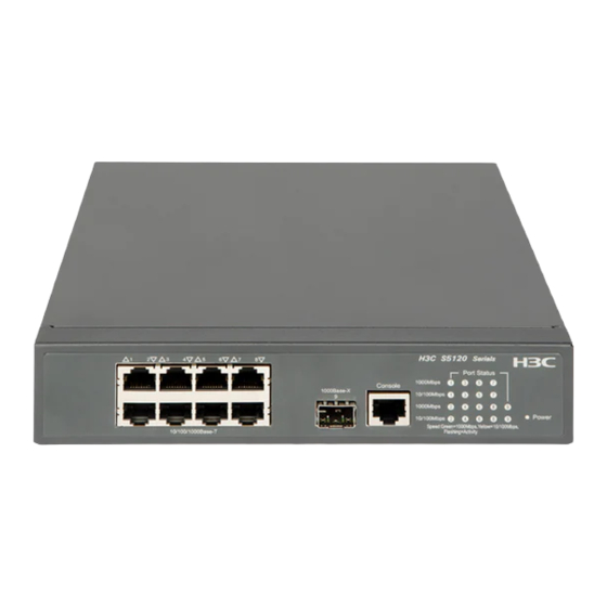
Appendix A Chassis views and technical specifications 10/100/1000Base-T autosensing Ethernet ports on the S5120-SI switch series are numbered from top to bottom and left to right. Chassis views S5120-9P-SI Figure 38 Front panel (1) 10/100/1000Base-T autosensing Ethernet port (2) 1000Base-X SFP port (3) Console port (4) Port status LED (5) Power status LED (Power) -
Page 41: S5120-28P-Si
Figure 41 Rear panel (1) AC-input receptacle (2) Grounding screw S5120-28P-SI Figure 42 Front panel (1) 10/100/1000Base-T autosensing Ethernet port (2) 1000Base-X SFP port (3) Console port (4) Port status LED (5) Power status LED (Power) Figure 43 Rear panel (1) AC-input receptacle (2) Grounding screw S5120-52P-SI... -
Page 42: S5120-9P-Pwr-Si
Figure 45 Rear panel (1) AC-input receptacle (2) Grounding screw S5120-9P-PWR-SI Figure 46 Front panel (1) 10/100/1000Base-T autosensing Ethernet port (2) Port LED mode switching button (3) Port status LED (4) Power status LED (Power) (5) Mode LED (6) Console port (7) 1000Base-X SFP port Figure 47 Rear panel (1) AC-input receptacle... -
Page 43: S5120-9P-Hpwr-Si
S5120-9P-HPWR-SI Figure 48 Front panel (1) 10/100/1000Base-T autosensing Ethernet port (2) Port LED mode switching button (3) Port status LED (4) Power status LED (Power) (5) Mode LED (6) Console port (7) 1000Base-X SFP port Figure 49 Rear panel (1) AC-input receptacle (2) Grounding screw S5120-28P-PWR-SI Figure 50 Front panel... -
Page 44: S5120-28P-Hpwr-Si
Figure 51 Rear panel (1) AC-input receptacle (2) Grounding screw S5120-28P-HPWR-SI The S5120-28P-HPWR-S switch includes two models: one with a depth of 360 mm (14.17 in) and the other with a depth of 420 mm (16.54 in). S5120-28P-HPWR-SI with a depth of 360 mm (14.17 in) Figure 52 Front panel (1) 10/100/1000Base-T autosensing Ethernet port (2) Port LED mode switching button... -
Page 45: Technical Specifications
S5120-28P-HPWR-SI with a depth of 420 mm (16.54 in) Figure 54 Front panel (1) 10/100/1000Base-T autosensing Ethernet port (2) Port LED mode switching button (3) RPS status LED (RPS) (4) Port status LED (5) Power status LED (Power) (6) Mode LED (7) Console port (8) 1000Base-X SFP port Figure 55 Rear panel... - Page 46 Rated voltage Rated voltage Input range: –52 VDC to range: –54 VDC to voltage –55 VDC –57 VDC Not supported Not supported Use an H3C RPS: input Use an H3C RPS: RPS1000-A3 or RPS1600-A RPS1600-A. • S5120-9P-PWR-S • • I: 10 W AC: 45.6 W...
- Page 47 S5120-28P-HP S5120-28P-HPW S5120-9P-PWR-SI S5120-28P-P WR-SI with a R-SI with a Item WR-SI depth of 420 depth of 360 mm S5120-9P-HPWR-SI mm (16.54 in) (14.17 in) • S5120-9P-PWR-S I: Left-to-right air aisle, without fans Left-to-right air Left-to-right air Left-to-right air • Cooling system aisle, three aisle, six built-in...
-
Page 48: Appendix B Ports And Leds
Appendix B Ports and LEDs Ports Console port The switch provides a console port on the front panel. Table 9 Console port specifications Item Specification Connector type RJ-45 Compliant standard EIA/TIA-232 Transmission baud rate 9600 bps to 115200 bps (defaulting to 9600 bps) •... - Page 49 • As a best practice, use H3C SFP transceiver modules for the S5120-SI switches. • H3C SFP transceiver modules are subject to change over time. For the most up-to-date list of SFP transceiver modules, contact your H3C sales representative or technical support engineer.
-
Page 50: Leds
POST has failed or a severe fault has occurred. The switch has been powered off. RPS status LED The H3C S5120-28P-HPWR-SI switch provides an RPS status LED on its front panel, indicating the RPS power supply status for the switch. Table 14 RPS status LED description... -
Page 51: 10/100/1000Base-T Autosensing Ethernet Port Status Led
LEDs are showing. You can use the port LED mode switching button to change the type of the information to display. Table 15 Mode LED description Status Description Steady green The port status LEDs indicate port rates. Mode Flashing green at 1 Hz The port status LEDs indicate port PoE status. -
Page 52: 1000Base-X Sfp Interface Status Led
Mode Switch model Port status LED Description The port is operating at 1000 Mbps. Fast flashing Data is transmitted or received at 1000 Mbps. Green The port is not up or is not operating at 1000 Steady Mbps. green The port is operating at 10/100 Mbps. (rate mode) Data is transmitted or received at 10/100... -
Page 53: Appendix C Lightning Protection For The Switch
Appendix C Lightning protection for the switch Installing a surge protected power strip CAUTION: Make sure the PE terminal of the power socket on the surge protected power strip is reliably grounded. If part of the AC power line is routed outdoors, use a surge protected power strip to protect the switch from being damaged by lightning strikes. - Page 54 Figure 56 Surge protected power strip • (1) LED (green) Steady green—The circuit is operating correctly. • Off—The circuit is damaged. (2) Grounding/pole detection LED (red) On indicates a wrong wire connection (the wire is not grounded or the live line and null line are reversely connected), and you need to check the power supply line.
-
Page 55: Index
Index A C E G I L M N P R S T V W AC and RPS power input failure,29 Magnet-mount kit,12 AC power input failure,29 Magnet-mounting the switch,12 Accessing the IRF fabric to verify the Mode LED,42 configuration,28 Mounting brackets,5 Attaching the mounting brackets to the... - Page 56 Wall-mounting the switch,10 Workbench-mounting the switch,10...
Need help?
Do you have a question about the H3C S5120-SI and is the answer not in the manual?
Questions and answers