H3C S5120-EI Series Installation Manual
Hide thumbs
Also See for S5120-EI Series:
- Operation manual (1191 pages) ,
- Command reference manual (242 pages) ,
- Configuration manual (206 pages)

Related Manuals for H3C S5120-EI Series


Summary of Contents for H3C S5120-EI Series
- Page 1 H3C S5120-EI Series Ethernet Switches Installation Manual Hangzhou H3C Technologies Co., Ltd. Manual Version: 5PW100-20090630...
- Page 2 SecPro, SecPoint, SecEngine, SecPath, Comware, Secware, Storware, NQA, VVG, V G, V G, PSPT, XGbus, N-Bus, TiGem, InnoVision and HUASAN are trademarks of Hangzhou H3C Technologies Co., Ltd. All other trademarks that may be mentioned in this manual are the property of their respective owners.
-
Page 3: About This Manual
About This Manual Organization H3C S5120-EI Series Ethernet Switches Installation Manual is organized as follows: Chapter Contents Briefly introduces the appearance, system description, as well as the 1 Product Overview features and applications of the S5120-EI series switches. Describes requirements... - Page 4 Related Documentation In addition to this manual, each H3C S5120-EI Series Ethernet Switch documentation set includes the following: Manual Description It is used for assisting the users in data configurations and H3C S5120-EI Series Ethernet typical applications. It includes Product Overview, Access...
- Page 5 Troubleshoot Online You will find support tools posted on the web site at http://www.h3cnetworks.com/ under Support, Knowledgebase. The Knowledgebase helps you troubleshoot H3C products. This query-based interactive tool contains thousands of technical solutions. Access Software Downloads Software Updates are the bug fix / maintenance releases for the version of software initially purchased with the product.
-
Page 6: Table Of Contents
Table of Contents 1 Product Overview ······································································································································1-1 Overview ·················································································································································1-1 Introduction to S5120-EI Series Ethernet Switches················································································1-2 S5120-28C-EI··································································································································1-2 S5120-52C-EI··································································································································1-3 S5120-28C-PWR-EI ························································································································1-4 S5120-52C-PWR-EI ························································································································1-5 S5120-24P-EI ··································································································································1-6 S5120-48P-EI ··································································································································1-7 Ports ························································································································································1-8 Console Port····································································································································1-8 10/100/1000Base-T Ethernet Port···································································································1-9 1000Base-X SFP Port ·····················································································································1-9 Combo Port ···································································································································1-10 LEDs······················································································································································1-11 System Status LED ·······················································································································1-11... - Page 7 Use Front Mounting Brackets and a Tray to Install a Switch ··························································3-5 Use Front and Rear Mounting Brackets to Install a Switch·····························································3-6 Use Front Mounting Brackets and Guide Rails to Install a Switch ··················································3-9 Mounting the Switch on a Workbench ··································································································3-11 Connecting the Grounding Cable··········································································································3-11 When a Grounding Strip is Available·····························································································3-12 Where a Grounding Conductor Can be Buried ·············································································3-13...
- Page 8 Configuration System Failure··················································································································6-4...
-
Page 9: Product Overview
(IRF) technology. You can connect multiple S5120-EI C switches through 10 GE ports to form a logical entity, thus to establish a new intelligent network with high reliability, expandability and manageability. The S5120-EI series include six models, and have the system specifications as shown in Table 1-1. Table 1-1 System specifications of the S5120-EI series... -
Page 10: Introduction To S5120-Ei Series Ethernet Switches
Rated voltage range: 100 VAC to 240 VAC, 50 Hz or 60 Hz AC input Input voltage range: 90 VAC to 264 VAC, 47 Hz to 63 Hz Use the external RPS power supply units recommended by H3C only. Input voltage Rated voltage range: 10.8 VDC to... -
Page 11: S5120-52C-Pwr
You can select one or two interface modules for your switch as needed. See Optional Interface Modules on page 1-15 for the interface module models supported by the S5120-EI series, and see Installing an Interface Module on page 3-17 for the installation of interface modules. - Page 12 You can select one or two interface modules for your switch as needed. See Optional Interface Modules on page 1-15 for the interface module models supported by the S5120-EI series, and see Installing an Interface Module on page 3-17 for the installation of interface modules.
- Page 13 You can select one or two interface modules for your switch as needed. See Optional Interface Modules on page 1-15 for the interface module models supported by the S5120-EI series, and see Installing an Interface Module on page 3-17 for the installation of interface modules.
-
Page 14: S5120-24P
You can select one or two interface modules for your switch as needed. See Optional Interface Modules on page 1-15 for the interface module models supported by the S5120-EI series, and see Installing an Interface Module on page 3-17 for the installation of interface modules. -
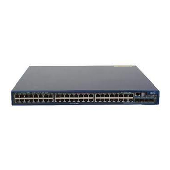
Page 15: S5120-48P
Ethernet ports and the four SFP ports comprise four Combo ports, with one port of a Combo port working at a time. Figure 1-9 Front panel of the S5120-24P-EI Ethernet switch (1) 10/100/1000 Base-T auto-sensing Ethernet port (2) 10/100/1000 Base-T auto-sensing Ethernet port status LED (3) 1000 Base-X SFP port (4) 1000Base-X SFP port status LED (5) Console port... -
Page 16: Ports
(4) “DO NOT REMOVE” label The S5120-48P-EI does not support any interface modules. Ports Console Port Each S5120-EI series provides one console port on the front panel. Table 1-2 describes the console port specifications. Table 1-2 Console port specifications Item... -
Page 17: 10/100/1000Base-T Ethernet Port
It can be connected to a serial port of a local or remote (through a pair of modems) PC running terminal emulation program. 10/100/1000Base-T Ethernet Port Each S5120-EI series provides 10/100/1000Base-T Ethernet ports on its front panel. Table 1-3 describes the specifications of the 10/100/1000Base-T Ethernet ports. Table 1-3 10/100/1000Base-T Ethernet port specifications... -
Page 18: Combo Port
The types of SFP transceivers may update with time. For information about transceivers, contact H3C technical support or marketing staff. For the models and specifications of each kind of transceivers, refer to H3C Low End Series Ethernet Switches Pluggable Modules Manual. -
Page 19: Leds
LEDs Table 1-6 LEDs Device support System Status LED All series RPS Status LED All series Port Mode LED All series Seven-Segment LED All series 10/100/1000Base-T Auto-Sensing Ethernet All series Port Status LED 1000Base-X SFP Port Status LED All series S5120-28C-EI, S5120-52C-EI, Interface Module Status LED S5120-28C-PWR-EI and S5120-52C-PWR-EI... -
Page 20: Port Mode Led
Port Mode LED The port mode LED on the S5120-EI series can display the working status of a port for you to obtain more device information. You can use the port mode switching button to change the status of the port mode LED. -
Page 21: 10/100/1000Base-T Auto-Sensing Ethernet Port Status Led
Status Description System status Seven-segment LED LED (PWR) The LED flashes t. Steady red Over-temperature alarm The LED displays C. The current switch is the command switch in the cluster. The LED displays S. The current switch is a member switch in the cluster. -
Page 22: 1000Base-X Sfp Port Status Led
Table 1-13 10/100/1000Base-T auto-sensing Ethernet port LEDs description Status Description Port mode Ethernet port status The port operates at a rate of 1000 Mbps; the LED is fast Steady green flashing when data is being sent and/or received on the port. Steady The port operates at a rate of 10/100 Mbps;... -
Page 23: Interface Module Status Led
No interface module is installed. Optional Interface Modules The S5120-EI series (excluding S5120-24P-EI and S5120-48P-EI) provide two interface module slots on the rear panel. You can select the interface modules in Table 1-16 as needed. The S5120-E1 series support IRF, requiring physical connections between devices. The 10 GE ports of the supported interface modules support IRF, allowing you to connect the switches through these 10 GE ports for IRF implementation. -
Page 24: Short-Haul Dual-Port 10 Ge Cx4 Interface Module
A short-haul dual-port 10 GE CX4 interface module provides two 10 Gbps electrical ports and supports CX4 electrical and protocol standards. Only H3C’s CX4 power cables can be used for connecting the CX4 ports. A CX4 cable is hot swappable and its maximum transmission distance is 3 m (9.84 ft.), which is suitable for short-distance connections only. -
Page 25: Dual-Port 10 Ge Sfp+ Interface Module
A dual-port 10 GE SFP+ interface module provides two 10 Gbps SFP+ ports. You can insert an SFP+ transceiver into the port to connect it to another SFP+ port through an optical fiber, or an SFP+ cable provided by H3C. For details about the supported SFP+ transceivers and SFP+ cables, refer to Table 1-18. -
Page 26: Dual-Port 10 Ge Xfp Interface Module
Figure 1-18 SFP+ cable You are recommended to use SFP+ transceivers and SFP+ cables of H3C on the S5120-EI series. The types of SFP+ transceivers and SFP+ cables may update with time. For information about transceivers, contact H3C technical support or marketing staff. -
Page 27: One-Port 10 Ge Xfp Interface Module
(24.85 mi.) The types of XFP transceivers may vary over time. Consult H3C marketing personnel or technical support personnel to obtain the latest information about XFP transceivers. For specifications of XFP transceivers, refer to H3C Low End Series Ethernet Switches Pluggable Module Manual. -
Page 28: Description Of Leds Of Interface Modules
Description of LEDs of Interface Modules There is a LED for each port on the interface module panel. Table 1-20 describes the LEDs. Table 1-20 Description of LEDs on interface modules Mark Status Description The port is normally connected. This LED is The LED blinks quickly when the Port LED of an not affected... -
Page 29: Preparing For Installation
When replacing interface modules, wear ESD-preventive gloves to avoid damaging the cards. Installation Site The S5120-EI series must be used indoors. You can mount your switch in a rack or on a workbench, but make sure: Adequate clearance is reserved at the air inlet/exhaust vents for ventilation. -
Page 30: Electromagnetic Susceptibility
Laser Safety The S5120-EI series are Class 1 laser devices. When the optical ports on the S5120-EI series are operating, do not stare into the optical ports because the laser light emitted by the optical fiber may hurt your retina. -
Page 31: Installation Tools
Staring into the laser beam produced by the fiber may hurt your eyes. Installation Tools Flathead screwdriver Phillips screwdriver ESD-preventive wrist strap The installation tools are not shipped with the S5120-EI series. -
Page 32: Installing The Switch
When you ask your sales agent to maintain the switch, you must ensure that the dismantlement-preventive seal on a mounting screw of the H3C switch chassis is intact. If you want to open the chassis, you should contact the agent for permission. Otherwise, you will bear any consequence resulted from your actions without permission. -
Page 33: Installing The Switch Into A 19-Inch Rack Using Mounting Brackets
The S5120-28C-EI, S5120-52C-EI, S5120-28C-PWR-EI, and S5120-52C-PWR-EI support IRF. For details about implementation of the IRF system and installation procedures, refer to Installing Switches for a Stack. Installing the Switch into a 19-Inch Rack Using Mounting Brackets Installation Modes You can install a switch into a 19-inch standard cabinet in one of the following four ways: Use front mounting brackets Use front mounting brackets and a tray Use front mounting brackets and rear mounting brackets... -
Page 34: Introduction To Mounting Bracket
(1) Screw hole used to fix the mounting bracket to the cabinet (Use one M6 screw) For the selection of front and rear mounting brackets, see Table 3-2. Table 3-2 Selection of mounting bracket for S5120-EI Series Ethernet switches Configuration type of... -
Page 35: Introduction To Guide Rail
(3) Slotted hole 2: Used to fix the guide rail to the front bracket Guide rails purchased from H3C apply only to standard cabinets 1,000 mm (39.37 in.) deep. Use other supports to substitute for guide rails in the case of other cabinet depths. -
Page 36: Use Front Mounting Brackets And A Tray To Install A Switch
(3) Front mounting bracket Use Front Mounting Brackets and a Tray to Install a Switch All models of the S5120-EI series support installation using front mounting brackets together with a tray. Follow these steps to install a switch into a 19-inch standard cabinet: Step1 Wear an ESD-preventive wrist strap and ensure a good skin contact and grounding. -
Page 37: Use Front And Rear Mounting Brackets To Install A Switch
Step5 Place the switch on the tray horizontally, slide the tray into the cabinet, and fix the other end of mounting brackets to the front brackets with crews and captive nuts, as shown in Figure 3-6. Use Front and Rear Mounting Brackets to Install a Switch Only the S5120-28C-PWR-EI and S5120-52C-PWR-EI support installation using front mounting brackets together with rear mounting brackets. - Page 38 Figure 3-8 Fix rear mounting brackets (1) Rear square-holed post (2) Rear mounting bracket Step6 Hold the bottom of the switch with one hand and the front part of the switch with the other hand, and push the switch into the cabinet gently, as shown in Figure 3-9. Figure 3-9 Fix front and rear mounting brackets (1) Front square-holed post (2) Load-bearing screw: Used to bear the weight...
- Page 39 Figure 3-10 Effect diagram of front and rear mounting bracket installation (1) (1) Rear panel (2) Rear square-holed post (3) Load-bearing screw (4) Rear mounting bracket Step7 Fix the other end of the front mounting brackets to the front brackets with screws and captive nuts and ensure that front and rear mounting brackets have fixed the switch in the cabinet securely, as shown in Figure 3-11.
-
Page 40: Use Front Mounting Brackets And Guide Rails To Install A Switch
(6) Front square-holed post Use Front Mounting Brackets and Guide Rails to Install a Switch All the models of the S5120-EI series support installation using front mounting brackets together with guide rails. Follow these steps to install a switch into a 19-inch standard cabinet: Step1 Wear an ESD-preventive wrist strap and ensure a good skin contact and grounding. - Page 41 Figure 3-12 Install guide rails Step5 Hold the two sides of the switch and slide it gently along the guide rails into the cabinet until it is located in a proper position, as shown in Figure 3-13. Ensure that the bottom side of the guide rails and the switch are in close contact.
-
Page 42: Mounting The Switch On A Workbench
Figure 3-14 Effect diagram of front mounting bracket and guide rail installation (1) Rear panel (2) Guide rail Ensure a clearance of 1U (44.45 mm, namely, 1.75 inches) between devices for the purpose of heat dissipation. Mounting the Switch on a Workbench In many cases, standard 19-inch racks are not available. -
Page 43: When A Grounding Strip Is Available
When a Grounding Strip is Available When a grounding strip is available at the installation site, attach one end of the yellow-green grounding cable (PGND cable) of the switch to the grounding screw on the grounding strip (the grounding screw and the grounding hole are on the rear panel of the switch and are marked with a grounding sign). -
Page 44: Where A Grounding Conductor Can Be Buried
Figure 3-16 Connect the PGND cable to the grounding strip (1) Grounding post (2) Grounding strip (3) PGND cable (4) Hex nut The fire main and lightning rod of a building are not suitable for grounding the switch. The ground wire of the switch should be connected to the grounding device for the equipment room. -
Page 45: Connecting The Power Cords
are well connected, and the three-wire input cable of the PGND cable is used for the power supply cable. If the PE wire of the AC power supply is not grounded at the power distribution room or AC transformer side, report the problem and make reconstructions. Figure 3-18 Ground through an AC power PE wire (1) Three-wire AC power input cable (2) Switch rear panel... - Page 46 Step5 Connect the other end of the AC power cord to the external AC power supply system. Step6 Check whether the system status LED (PWR) on the front panel of the switch is ON. If the LED is ON, it shows the power cord is properly connected.
-
Page 47: Connecting The Rps Power Cord
Connecting the RPS Power Cord Connect RPS power cords of S5120-28C-EI, S5120-52C-EI, S5120-24P-EI, and S5120-48P-EI The S5120-28C-EI, S5120-52C-EI, S5120-24P-EI and S5120-48P-EI can work with RPS500-A3 using its +12 V/10.5 A output and a 0404A03C power cord. Follow these steps to connect an RPS power cord to the switch: Step1 Connect one end of the chassis ground wire to the grounding screw on the rear panel of the chassis and the other end to the ground as near as possible. -
Page 48: Installing An Interface Module
Step2 Keep the upside of the RPS plug on top and plug it in the RPS DC receptacle (see callout 1 in Figure 3-25). (If you plug it upside down, the insertion is not smooth because of the specific structure design of the RPS DC receptacle and the RPS plug.) Step3 Use a flat-blade screwdriver to fix the two screws on the RPS plug clockwise to secure the plug to the RPS DC receptacle (see callout 2 in Figure 3-25). -
Page 49: Removing An Interface Module
Step4 Tighten the captive screws with a Phillips screwdriver to fix the interface module. Figure 3-27 Install an interface module (2) Keep the removed filler panel properly for future use. When tightening the fastening screws at both sides of the optional module with a screwdriver or an electric screwdriver, make sure that the torque is not bigger than 0.4 N-m. -
Page 50: Installing Dedicated Cx4/Sfp+ Cable
Step2 Hold the plug of the SFP+ cable, pull the handle at the end of the plug to horizontally unplug the plug of the SFP+ cable from the SFP+ port of the switch. Dedicated CX4/SFP+ cable of the S5120-EI series is hot pluggable. Make sure that the cable bending radius is no less than eight times of the cable diameter when dedicated CX4/SFP+ cable is connected. -
Page 51: Installation Flow For A Switch Stack
Installation Flow for a Switch Stack Figure 3-28 Installation flow for a switch stack Start Draw a plan for a stack of switches Install switches to the correct position as per the plan Connect the PGND cables and power cords for the switches Power on the swtiches Install interface modules Configure software for... -
Page 52: Drawing A Plan For The Switch Stack
The S5120-EI series support two to four switches in a stack. The S5120-EI series support aggregation of the 10 GE ports. You can assign the two 10 GE ports of an interface module to an aggregation group to expand the bandwidth for the stack. - Page 53 Before connecting the cables, determine the actual position of the member devices and the length of the cables, and observe the following: Understand the neighbor devices for one another Install the interface modules in proper slots as needed. Each S5120-EI series provides two expansion slots. Determine the ports on different devices to be connected.
- Page 54 port of another interface module, that is, two ports at the same side cannot be connected, as shown in Figure 3-31. Figure 3-31 Cable connections in a switch stack system in the non-aggregate mode When 2-port interface modules are adopted in a stack with ports operating in the aggregation mode, ports of MOD 1 can only be connected to ports of MOD 2, and the locations of the ports of the interface modules are not limited.
-
Page 55: Verifying The Installation
Figure 3-33 Cable connections for a stack with 1-port interface modules Verifying the Installation Check whether the selected power is the same as the power label on the switch; Check whether the ground wire is connected; Check whether the power cords are connected correctly; Check whether all the interface cables are routed indoors. -
Page 56: Starting And Configuring The Switch
Starting and Configuring the Switch Setting up the Configuration Environment Set up the configuration environment as follows: Connect a terminal (a PC in this example) to the console port on the switch with a console cable. Figure 4-1 Network diagram for configuration environment setup Connecting the Console Cable Console Cable A console cable is an 8-core shielded cable. -
Page 57: Connection Procedure
RJ-45 Signal Direction DB-9 ← → → → → Connection Procedure When you want to use the terminal to configure the switch, follow these steps to connect a terminal device to the switch using the console cable: Step1 Plug the DB-9 female connector of the console cable to the serial port of the console terminal or PC. Step2 Connect the RJ-45 connector of the console cable to the console port of the switch. - Page 58 Data bits: 8 Parity: None Stop bits: 1 Flow control: None Emulation: VT100 The specific procedure is as follows: Step1 Select Start > Programs > Accessories > Communications > HyperTerminal to enter the HyperTerminal window. The Connection Description dialog box appears, as shown below. Figure 4-3 Connection description of the HyperTerminal Step2 Type the name of the new connection in the Name text box and click OK.
- Page 59 Step3 Click OK after selecting a serial port. The following dialog box appears. Set Bits per second to 9600, Data bits to 8, Parity to None, Stop bits to 1, and Flow control to None. Figure 4-5 Set the serial port parameters Step4 Click OK after setting the serial port parameters and the system enters the HyperTerminal window shown below.
-
Page 60: Booting The Switch
Powering on the Switch All the S5120-EI series Ethernet switches have the same Boot ROM display style. This document uses the Boot ROM display of S5120-52C-PWR-EI as an example: Starting.. - Page 61 Copyright (c) 2004-2009 Hangzhou H3C Tech. Co., Ltd. Creation date : May 7 2009, 09:06:06 CPU Clock Speed : 264MHz BUS Clock Speed : 33MHz Memory Size : 128MB Mac Address : 000fe2d258fb Press Ctrl-B to enter Boot Menu... 1 The last line asks whether you want to enter the Boot Menu.
- Page 62 User interface aux0 is available. Press ENTER to get started. The appearance of "Press ENTER to get started" indicates that the automatic startup of the switch is complete. Press Enter. The following prompt is displayed: <H3C> You can configure the switch now.
-
Page 63: Changing The Startup Mode
7. Skip current configuration file 8. Set bootrom password recovery 9. Set switch startup mode 0. Reboot Enter your choice(0-9): Enter 0. The system reboots in normal mode and displays the following information: Starting..*********************************************************** H3C S5120-52C-PWR-EI BOOTROM, Version 100... - Page 64 *********************************************************** Copyright (c) 2004-2009 Hangzhou H3C Tech. Co., Ltd. Creation date : May 7 2009, 09:06:06 CPU Clock Speed : 264MHz BUS Clock Speed : 33MHz Memory Size : 128MB Mac Address : 000fe2d258fb Press Ctrl-B to enter Boot Menu... 5 In normal startup mode, the waiting time here is five seconds.
- Page 65 You can configure the switch now. The H3C Series switches provide abundant command views. For detailed descriptions about the configuration commands and CLI, refer to H3C S5120-EI Series Ethernet Switches Operation Manual and H3C S5120-EI Series Ethernet Switches Command Manual.
-
Page 66: Boot Rom And Host Software Loading
If your terminal is directly connected to the switch, you can load Boot ROM and host software locally. Before loading the software, make sure that your terminal is correctly connected to the switch to insure successful software loading. Boot Menu Starting..*********************************************************** H3C S5120-52C-PWR-EI BOOTROM, Version 100... - Page 67 *********************************************************** Copyright (c) 2004-2009 Hangzhou H3C Tech. Co., Ltd. Creation date : May 7 2009, 09:06:06 CPU Clock Speed : 264MHz BUS Clock Speed : 33MHz Memory Size : 128MB Mac Address : 000fe2d258fb Press Ctrl-B to enter Boot Menu... 1 Press Ctrl + B.
-
Page 68: Loading Software Using Xmodem Through Console Port
The loading process of the Boot ROM software is the same as that of the host software, except that during the Boot ROM loading process, you must enter the different digit after entering the Boot Menu and the system gives somewhat different prompts. The following text mainly describes the Boot ROM loading process. - Page 69 Task Remarks Restart the switch to make the updated Boot Required ROM file effective Enter the Boot ROM update menu on the switch Enter the Boot ROM menu, and then enter 6 or press Ctrl + U after the system displays “Enter your choice(0-9):”...
- Page 70 To ensure communication between the terminal and the switch, the baud rate of the serial port on the terminal should be consistent with that of the console port on the switch. Step1 Select Call > Disconnect in the HyperTerminal window to disconnect the terminal from the switch. Figure 5-1 Disconnect the terminal from the switch Step2 Select File >...
- Page 71 Figure 5-3 Modify the baud rate Step3 Select Call > Call to reestablish the connection. Figure 5-4 Reestablish the connection The new settings can take effect only after you reestablish the connection. Download the Boot ROM file Step1 Press Enter in the HyperTerminal window to start downloading the program. The system displays the following information: CCCCCCCCCCCCCCCCCC Press Ctrl + X to quit downloading files;...
- Page 72 Step2 Select Transfer > Send File in the HyperTerminal’s window. Click Browse in the pop-up dialog box (as shown in Figure 5-5) to select the application file to be downloaded (for example, bootrom.btm), and select Xmodem from the Protocol drop-down list. Figure 5-5 Send file dialog box Step3 Click Send.
-
Page 73: Loading Software Using Tftp Through Ethernet Port
Restore the download rate to the default Set the baud rate to 9600 bps (refer to Change the rate of the serial port on the terminal on page 5-4 for detailed operation). Restart the switch to make the updated Boot ROM file effective Press Enter in the HyperTerminal window to return to the Boot ROM update menu. - Page 74 Step2 Run the TFTP server program on the TFTP server, and specify the path of the program to be loaded. TFTP server program is not provided with the H3C Series switches. Step3 Run the terminal emulation program on the configuration PC. Start the switch. Then enter the Boot Menu.
-
Page 75: Loading Software Using Ftp Through Ethernet Port
Step6 Enter Y to start file downloading or N to return to the Boot ROM update menu. If you enter Y, the system begins to download and update the Boot ROM software. Upon completion, the system displays the following information to show the loading process is completed: Loading........done Bootrom updating..done! BOOT... - Page 76 Loading Boot ROM software Figure 5-8 Load Boot ROM software through FTP Switch Console port Ethernet port FTP Client FTP Server Step1 As shown in Figure 5-8, connect the switch through an Ethernet port to the FTP server, and connect the switch through the console port to the configuration PC.
-
Page 77: Loading Software Through Cli
Bootrom updating..done! BOOT MENU 1. Download application file to flash 2. Select application file to boot 3. Display all files in flash 4. Delete file from flash 5. Modify bootrom password 6. Enter bootrom upgrade menu 7. Skip current configuration file 8. - Page 78 [ftp] get S5120-EI.bin [ftp] get S5120-EI.btm [ftp] bye Step2 Update the Boot ROM program on the switch. <H3C> bootrom update file S5120-EI.btm This command will update BootRom file, Continue? [Y/N]y Updating BootRom, please wait... Upgrade Bootrom succeeded! Step3 Update the host software on the switch.
-
Page 79: Loading Software Using Tftp
If the space of the flash memory is not enough, you can delete the useless files in the flash memory before software downloading. Power interruption is not allowed during software loading. Loading Software Using TFTP The remote loading by using TFTP is similar to the remote loading by using FTP. The only difference is that it is TFTP that you use when loading software to the switch. -
Page 80: Maintenance And Troubleshooting
Maintenance and Troubleshooting Software Loading Failure If software loading fails, the system keeps running in original version. In this case, check if the physical ports are properly connected. If the ports are not properly connected, reconnect them correctly and restart the loading procedure. If the ports are properly connected, check the loading procedure information displayed on the HyperTerminal for input errors. -
Page 81: Power Supply Failure
Power Supply Failure The S5120-EI series switches use fixed power modules. Each of these fixed power modules has three input modes, namely, AC input, RPS input and both. You can check whether the power system of the switch fails by viewing the system status LED (PWR) and RPS status LED (RPS) on the front panel of the switch. -
Page 82: Fan Failure
Fan Failure You can check the system status LED and the seven-segment LED of an S5120-EI series to determine whether the fans operate normally. If a fan failure occurs, the two LEDs give an indication, as shown in Table 6-2. -
Page 83: Configuration System Failure
Only when the system status LED is steady red and the seven-segment LED is displayed as F does it indicate a fan failure. The S5120-EI series switches use fixed fans. If a fixed fan failure occurs, you cannot solve the problem by yourself. Please contact your sales agent or service engineer. - Page 84 Table of Contents Appendix A Lightning Protection of the Switch······················································································· A-1 Installation of Lightning Arrester for AC Power (Socket Strip with Lightning Protection) ······················ A-1 Appendix B Compliance and Safety Manual ···························································································· B-1 Regulatory Compliance Information······································································································· B-1 Regulatory compliance standards ·································································································· B-1 European Directives compliance····································································································...
-
Page 85: Appendix A Lightning Protection Of The Switch
Appendix A Lightning Protection of the Switch Installation of Lightning Arrester for AC Power (Socket Strip with Lightning Protection) Lightning arrester will not be shipped with the switch. You should purchase it by yourself if needed. If an outdoor AC power cord should be directly led to the switch, please serially connect the lightning arrester for AC power (Socket Strip with Lightning Protection) before you plug AC power cord into the switch, thus to prevent the possible damage to the switch due to lightning strike. - Page 86 Make sure that the arrester is well grounded before using the lightning arrester for power. After inserting AC power cord plug of switch into the socket of lightning arrester, if the green LED is on and the red LED does not alarm, it means that the lightning arrester of power is running and the function of lightning protection has taken effect.
-
Page 87: Appendix B Compliance And Safety Manual
CAN/CSA C22.2 No 60950-1 IEC 60950-1 EN 60950-1/A11 Safety AS/NZS 60950 EN 60825-1 EN 60825-2 FDA 21 CFR Subchapter J GB 4943 European Directives compliance LVD/EMC Directive S5120-EI SERIES products comply with the European Low Voltage Directive 2006/95/EC and EMC Directive 2004/108/EC. -
Page 88: Usa Regulatory Compliance
Directive and must be disposed of in a responsible manner. USA regulatory compliance FCC Part 15 S5120-EI SERIES comply with Part 15 of the FCC Rules. Operation is subject to the following two conditions: This device may not cause harmful interference. -
Page 89: Japan Regulatory Compliance
CISPR 22 compliance S5120-EI SERIES comply with the requirements of CISPR 22 for Class A Information Technology Equipment (ITE). Warning: If this equipment is used in a domestic environment, radio disturbance may arise. When such trouble occurs, the user may be required to take corrective actions. - Page 90 Before any operation is performed, please read the operation instructions and precautions carefully to minimize the possibility of accidents. The Note, Caution, Warning and Danger items in other manuals do not cover all safety precautions that should be followed. They are only the supplements to the safety precautions for operations as a whole.
- Page 91 为了避免可能发生的事故,请在进行任何操作前,仔细阅读设备操作手册和本章节的安全规范。手 册中 出现的说明、注意、警告、危险,不能涵盖所有的安全预防,仅仅是在整个操作过程中的安全 提示和补充。因此,负责安装和日常维护本设备的人员必须具备安全操作基本技能。 操作人员要按照当地的安全规范进行操作。出现在产品手册中的安全预防措施仅仅是当地安全规范 的补充。 在操作本设备时,请认真执行产品手册规定的安全规范。 设备安装、维护人员必须通过专业培训,并且掌握足够的操作技能和安规预防意识。只有专业人员 才能担任本设备的安装和维护工作。 Conventions Used Symbole Erläuterung 应用惯例 The symbols in this manual are shown in the following table. They are used to remind the reader of the safety precautions during equipment installation and maintenance. Die Symbole in diesem Handbuch verwendeten sind in der folgenden Tabelle dargestellt.
- Page 92 Um das technisch bedingte Restrisiko auf ein Minimum zu begrenzen, ist es unbedingt erforderlich, die folgenden Regeln zu beachten: 为了避免对人和设备造成伤害,请认真执行下列要求: Read all the instructions before operation. Lesen Sie alle Anweisungen sorgfältig durch, bevor Sie mit dem Arbeiten beginnen. 在进行操作前仔细阅读手册内容。 When installing the unit, always make the ground connection first and disconnect it last. Beachten Sie, dass bei der Installation des Systems stets zuerst die Erdverbindung angebracht wird und das die Erdverbindung stets als letztes getrennt wird.
-
Page 93: Electricity Safety Elektrische Sicherheit 用电安全
H3C S5120-EI may be powered by a DC RPS, if the Customer need the DC power source, the DC RPS power source must be supplied by H3C company, the RPS model is RPS500-AXXX made by Liteon or RPS800-AX made by VAPEL or RPS1000-AX made by Eltek (Where X may be 0-9 or A-Z or blank). - Page 94 When water is found in the rack, or the rack is damp, please immediately switch off the power supply. Sollte sich Wasser im Baugruppenträger befinden oder der Baugruppenträger feucht sein, ist die Energiezufuhr sofort zu unterbrechen und das System abzuschalten. 当有液体进入机架或机架有损坏时,请立即切断电源。...
- Page 95 Das Entfernen und Anbringen von Zuleitungen ist strengstens verboten. Kurzschlüsse zwischen innerem und äußerem Leiter können Lichtbögen oder Funkenflug verursachen, was zu Feuer oder einer Augenverletzung führen kann. 禁止安装和移动带电的线缆。因为导电体和带电的线缆,即使短暂接触,也会引起电火花或电弧,从而 导致失火或是伤害眼睛。 Before the power cable is installed or removed, the power switch must be turned off. Das System muss stets abgeschaltet werden, bevor die Zuleitung angebracht oder entfernt wird.
-
Page 96: Laser Laser激光辐射
High voltage and AC operations or operations on a steel tower and a mast on a thunderstorm day are prohibited. In order to prevent the equipment from being damaged by lightning, proper grounding is required. Arbeiten mit Hochspannung und Wechselstrom oder Arbeiten auf Stahltürmen und masten während eines Gewitters sind verboten.
Need help?
Do you have a question about the S5120-EI Series and is the answer not in the manual?
Questions and answers