Table of Contents
Advertisement
Quick Links
Download this manual
See also:
Instruction Manual
Advertisement
Table of Contents

Related Manuals for TESTO 6321


Summary of Contents for TESTO 6321
- Page 1 6321 · differential pressure transmitter P2A software · Parameterizing, adjusting and analyzing software Instruction manual GlobalTestSupply www. .com d Quality Products Online at: sales@GlobalTestSupply.c...
-
Page 2: Safety And The Environment
Pos: 8 /TD/Sicherheit und Umwelt/Sicherheit gewährleisten/MUF 63xx/Fachpersonal @ 3\mod_1234794940409_79.doc @ 26337 @ Any additional work must only be carried out by authorized personnel. Otherwise testo will not accept any responsibility for the proper functioning of the instrument after repair and for the validity of certifications. -
Page 3: About This Document
> At the end of its useful life, send the product to the separate collection for electric and electronic devices (observe local regulations) or return the product to Testo for disposal. Pos: 11 /TD/Überschriften/MUF/Zu diesem Dokument @ 3\mod_1234793991331_79.doc @ 26242 @ 1 About this document Pos: 12 /TD/Sicherheit und Umwelt/Zu diesem Dokument/Verwendung (Standard) @ 0\mod_1173775068554_79.doc @ 337 @ 5... -
Page 4: Table Of Contents
3 Contents Pos: 17 /TD/Überschriften/MUF/Inhalt @ 3\mod_1234794019831_79.doc @ 26261 @ 1 Contents Safety and the environment ..............3 About this document ................4 Contents ....................5 Transmitter ....................7 4.1. Specifications .................. 7 4.1.1. Functions and use ................... 7 4.1.2. Scope of delivery ..................... - Page 5 6.1. Questions and answers ..............36 6.2. Accessories and spare parts ............36 6.2.1. Ordering options for testo 6321 transmitter (0555 6321) ........ 37 Pos: 18 /TD/--- Seitenwechsel --- @ 0\mod_1173774430601_0.doc @ 283 @ GlobalTestSupply www. .com d Quality Products Online at:...
-
Page 6: Transmitter
Operating instructions • Calibration report Pos: 23 /TD/Leistungsbeschreibung/Technische Daten/MUF 63xx/MUF 6781 Abmessungen @ 3\mod_1239806330094_79.doc @ 31183 @ 3 4.1.3. Dimensions Pos: 24 /TD/Leistungsbeschreibung/Technische Daten/MUF 63xx/MUF 6321 @ 3\mod_1241601145321_79.doc @ 32604 @ 35555555555555555555 4.1.4. Technical data Parameter • Differential pressure GlobalTestSupply www. - Page 7 4 Transmitter Accuracy The specifications are only valid if the positive pressure is applied at the positive pressure connection. • 1.2 % of measuring range, additional ±0.3 Pa intrinsic error • = 0.05 % of measuring range per degree Kelvin of K slope drift deviation from nominal temperature 22 °C •...
- Page 8 2500 hPa Upon delivery and following a factory reset the readings are shown in the display in the unit that was ordered via the KMAT option Fxx, see Ordering options for testo 6321 transmitter (0555 6321) page 37. Meas. cycle •...
- Page 9 4 Transmitter Maximal load • 10 kΩ (voltage output) Analog output • 0 to 1 V ± 2.5 mV (4-wire) or • 0 to 5 V ± 12.5 mV (4-wire) or • 0 to 10 V ± 25 mV (4-wire) or •...
-
Page 10: Product Description
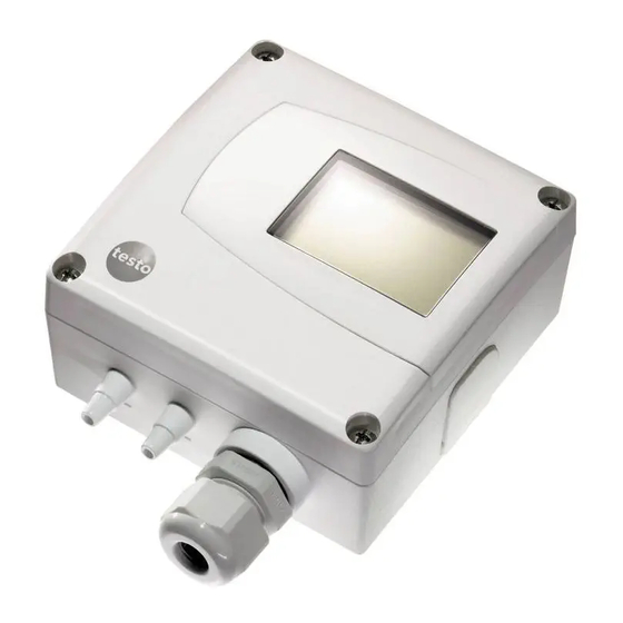
Warranty conditions: see website www.testo.com/warranty Pos: 25 /TD/Überschriften/MUF/1.2/2.2 Produktbeschreibung @ 3\mod_1234258723551_79.doc @ 24008 @ 2 4.2. Product description Pos: 26 /TD/Produktbeschreibung/Übersicht/MUF 63xx/Auf einen Blick MUF 6321 @ 3\mod_1241599865646_79.doc @ 32583 @ 3 4.2.1. At a glance 1 Display for showing reading... -
Page 11: Scaling
PLC. With the alarm definition, however, the physical measuring range limits are decisive. Pos: 28 /TD/Produktbeschreibung/Übersicht/MUF 63xx/Tabelle Skalierung MUF 6321 @ 3\mod_1241617696391_79.doc @ 32646 @ Measuring range/ Maximum scaling standard scaling... -
Page 12: Commissioning
4 Transmitter Measuring range/ Maximum scaling standard scaling -20 to 20 hPa -30 to 30 -50 to 50 hPa -100 to 100 -100 to 100 hPa -200 to 200 -500 to 500 hPa -1000 to 1000 -1000 to 1000 hPa -2000 to 2000 -2000 to 2000 hPa -4000 to 4000... -
Page 13: Wiring The Instrument
1. Slide plastic bracket (2) on the back of instrument onto rear panel bracket until it engages (see arrows). 2. Insert screw (4) through hole (3) and screw into rear panel bracket. Pos: 31 /TD/Erste Schritte/MUF 63xx/Gerät verdrahten 6321 @ 3\mod_1241618087115_79.doc @ 32667 @ 344 4.3.2. Wiring the instrument WARNING Electrical voltage! >... - Page 14 4 Transmitter CAUTION Damage to electronic components! > The terminal strip can be removed from the circuit board in order to screw on the cable ends. After wiring, be sure to completely attach the terminal strip on the contact pins as pre- assembled.
-
Page 15: 4-Wire System
4 Transmitter 4.3.2.1. 4-wire system Voltage output (4-wire, 0 to 1 V/0 to 5 V/0 to 10 V)/voltage output (4-wire, 4 to 20 mA): U = 20 to 30 V DC/AC 4.3.2.2. 3-wire system All ground connections are connected to one another (= one collective ground connection). -
Page 16: Maintenance And Cleaning
4 Transmitter 4.4. Maintenance and cleaning Pos: 33 /TD/Produkt instand halten/MUF 63xx/Gehäuse reinigen 6321 @ 3\mod_1241092795617_79.doc @ 32303 @ 3 4.4.1. Cleaning housing • Only clean the housing carefully with a moist cloth. • Do not use aggressive cleaning agents. -
Page 17: Parameterizing, Adjusting And Analyzing Software (P2A Software)
Generally, all newer testo transmitters (as of 2007) are supported. • Included with every testo transmitter that is bought new is a CD that contains a free upgrade of the software, which includes the device drivers for all transmitters that can be attached at this time. -
Page 18: System Requirements
5 Parameterizing, adjusting and analyzing software (P2A software) If you use various instruments of the same type, you can create parameter files once (e.g. by saving the appropriate instrument file as the parameter file) and transmit these onto the other instruments. -
Page 19: First Steps
5.2.2. Starting the software 5.2.2.1. Starting the program > Select: [Start] > All Programs > Testo > P2A Software. The program window is opened (see User interface page 21). 5.2.2.2. Establishing a connection with the instrument Multiple instruments can be attached, however only one connection is active at all times. -
Page 20: Activating The Connection With The Instrument
5 Parameterizing, adjusting and analyzing software (P2A software) 3. Connect instrument/adapter to the PC via the USB interface. The instrument file of the attached instrument is shown in the file list. 5.2.2.3. Activating the connection with the instrument > Click on the desired instrument file. The selected file is marked in colour and the connection with the instrument is activated. - Page 21 5 Parameterizing, adjusting and analyzing software (P2A software) Menu Command Explanation Edit Copy Copies the parameters of the marked instrument or parameter file in the cache. Paste Pastes the parameters from the cache in the marked instrument or parameter file. Activates/deactivates the toolbar View Toolbar...
- Page 22 5 Parameterizing, adjusting and analyzing software (P2A software) Icon File Explanation <Type> <Serial number> Parameter file <Date> <Time>.cfp Symbol shows a transmitter with a white File name can be changed. P for parameter file in The name can be selected freely, the upper left corner but it is recommended that you retain the reference to the...
-
Page 23: Editing Instrument/Parameter File
5 Parameterizing, adjusting and analyzing software (P2A software) Pos: 45 /TD/Produkt verwenden/MUF 63xx/P2A/Geräte-/Parameterdatei bearbeiten @ 3\mod_1234358080444_79.doc @ 24303 @ 34 5.3.2. Editing instrument/parameter file 5.3.2.1. Changing instrument/parameter file ✓ The desired instrument/parameter file is marked. 1. Click on [Change parameterization]. Properties of <Instrument type>... - Page 24 5 Parameterizing, adjusting and analyzing software (P2A software) Field Explanation Unit/analog output Unit: 0 to 1 V/5 V/10 V or 4 to 20 mA. (graphic) Vertical: Current version of the analog output (cannot be changed). Horizontal: Min./max. scale end points of selected unit.
-
Page 25: Creating A New Instrument File
The original name (Instrument type, Serial number) is suggested with the current date/time as standard, e.g. "testo 6321 01234578 061120 1403.cfp". For a standard installation, the files are saved under "C:\Documents and Settings\All Users\Shared Documents\P2A Software". The path can differ depending on the version of the operating system. -
Page 26: Copying And Pasting Parameters
5 Parameterizing, adjusting and analyzing software (P2A software) Pos: 50 /TD/Produkt verwenden/MUF 63xx/P2A/Parameter kopieren/einfügen @ 3\mod_1234358826054_79.doc @ 24360 @ 4 5.3.2.5. Copying and pasting parameters The parameters of a parameter file can be transmitted to an instrument file or another parameter file from the same instrument type. -
Page 27: Analyzing/Testing The Instrument
The values are reset to the customer-specific factory settings. [OK] [Cancel] 4. Click on to close the dialogue. Pos: 55 /TD/Produkt verwenden/MUF 63xx/P2A/Analogausgang testen 6321 @ 4\mod_1244461179628_79.doc @ 44787 @ 4 5.3.3.3. Testing analog output ✓ The required instrument file is marked. 1. Click on [Test/analyze transmitter]. - Page 28 5 Parameterizing, adjusting and analyzing software (P2A software) Field/button Explanation Transmitter test Monitoring of analog outputs Current reading Readings are updated every second. Unit Unit according to the type of analog output. Default value Freely definable output value for the respective type of analog output (V or mA), 1 decimal place.
-
Page 29: Displaying Min./Max. Values
5 Parameterizing, adjusting and analyzing software (P2A software) Pos: 56 /TD/Produkt verwenden/MUF 63xx/P2A/Min-/Max-Werte anzeigen 635x @ 3\mod_1242135985269_79.doc @ 32803 @ 4 5.3.3.4. Displaying min./max. values The transmitter saves the minimum or maximum value for each channel (measured since the last voltage supply or since the last manual reset). -
Page 30: Adjusting The Transmitter
Pos: 57 /TD/Überschriften/MUF/x.x.x Messumformer abgleichen @ 4\mod_1244530152797_79.doc @ 44885 @ 3 5.3.4. Adjusting the transmitter Pos: 58 /TD/Produkt verwenden/MUF 63xx/P2A/Messumformer abgleichen 6321 @ 4\mod_1244460546736_79.doc @ 44755 @ This function is used to adjust an attached instrument. The following adjustments may be carried out using the software: •... -
Page 31: Adjusting The Analog Output
The n-point adjustment must always be carried out to its full extent and in good time at all selected adjustment points. 9. Disconnect connections between the pressure sensor and the pressure connections of the testo 6321. Pos: 60 /TD/Produkt verwenden/MUF 63xx/P2A/Analogausgang abgleichen _6321 @ 4\mod_1244461217550_79.doc @ 44819 @ 4 5.3.4.2. -
Page 32: Transmitter History
Pos: 61 /TD/Überschriften/MUF/2.3.5 Messumformer-Historie @ 3\mod_1237373806926_79.doc @ 29846 @ 3 5.3.5. Transmitter history Pos: 62 /TD/Produkt verwenden/MUF 63xx/P2A/Messumformer-Historie 6321 @ 4\mod_1244458681753_79.doc @ 44723 @ Parameterizations and adjustment processes are registered in the transmitter with an operating hours stamp. In the history overviews (explained later in more detail), past processes and events can be made visible. - Page 33 5 Parameterizing, adjusting and analyzing software (P2A software) 1. Mark the instrument file of the connected instrument. 2. Click on the [Transmitter history] button. Properties of <Instrument type> <Serial number> dialogue is opened with the Transmitter history register. 3. Click on the required entry in the list to change the display. Field Explanation Operating hours /...
- Page 34 5 Parameterizing, adjusting and analyzing software (P2A software) Field Explanation Selection of adjustment histories: n-point adjustments Analog adjustments. Operating hours / Operating hour/time stamp at which the date/time change at the instrument was performed. User Name with which the user is logged into the operating system.
-
Page 35: Tips And Assistance
Pos: 66 /TD/Überschriften/8.2 Zubehör und Ersatzteile @ 0\mod_1177402058734_79.doc @ 1102 @ 2 6.2. Accessories and spare parts Pos: 67 /TD/Tipps und Hilfe/Zubehör und Ersatzteile/MUF63xx/Zubehör Ersatzteile MUF 6321 @ 3\mod_1239975742627_79.doc @ 31715 @ Description Article no. Interface and software... -
Page 36: Ordering Options For Testo 6321 Transmitter (0555 6321)
For a complete list of all accessories and spare parts, please refer to the product catalogues and brochures or look up our website at: www.testo.com Pos: 68 /TD/Tipps und Hilfe/Zubehör und Ersatzteile/MUF63xx/Bestelloptionen MUF 6321 @ 3\mod_1239975748830_79.doc @ 31736 @ 3 6.2.1. Ordering options for testo 6321 transmitter... - Page 37 6 Tips and assistance Order code Characteristic Cxx Display Without display With display Exx Housing colour and logo Grey housing, testo logo in colour White housing, without testo logo White housing, black-and-white testo logo Fxx Differential pressure unit Pa/Min/Max hPa/Min/Max kPa/Min/Max...
Need help?
Do you have a question about the 6321 and is the answer not in the manual?
Questions and answers