Sign In
Upload
Download
Table of Contents
Contents
Add to my manuals
Delete from my manuals
Share
URL of this page:
HTML Link:
Bookmark this page
Add
Manual will be automatically added to "My Manuals"
Print this page
×
Bookmark added
×
Added to my manuals
Manuals
Brands
Keithley Manuals
AC Power Distribution
6220 DC
User manual
Keithley 6220 DC User Manual
6220 dc current source 6221 ac and dc current source
Hide thumbs
1
2
3
4
5
6
7
8
Table Of Contents
9
10
11
12
13
14
15
16
17
18
19
20
21
22
23
24
25
26
27
28
29
30
31
32
33
34
35
36
37
38
39
40
41
42
43
44
45
46
47
48
49
50
51
52
53
54
55
56
57
58
59
60
61
62
63
64
65
66
67
68
69
70
71
72
73
74
75
76
77
78
79
80
81
82
83
84
85
86
87
88
89
90
91
92
93
94
95
96
97
98
99
100
101
102
103
104
105
106
107
108
109
110
111
112
113
114
115
116
117
118
119
120
121
122
123
124
125
126
127
128
129
130
131
132
133
134
135
136
137
138
139
140
141
142
143
144
145
146
147
148
149
150
151
152
153
154
155
156
157
158
159
160
161
162
163
164
165
166
167
168
169
170
171
page
of
171
Go
/
171
Contents
Table of Contents
Bookmarks
Table of Contents
Safety Precautions
Table of Contents
1 Getting Started
Introduction
User's Manual Content and Structure
Capabilities and Features
General Information
Warranty Information
Contact Information
Safety Symbols and Terms
Unpacking and Inspection
Options and Accessories
Front and Rear Panel Familiarization
Front Panel Summaries
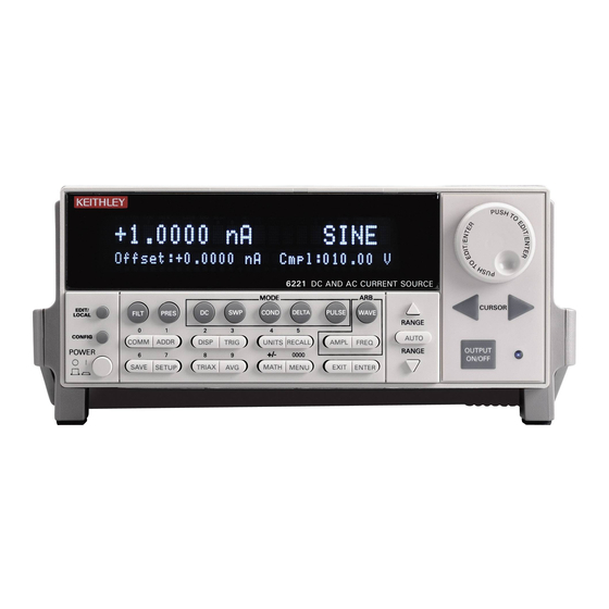
Figure 1-1 Models 6220 and 6621 Front Panels
Rear Panel Summaries
Getting Started
Figure 1-2 Model 622X Rear Panel
Heat Sink and Cooling Vents
Power-Up
Line Power Connection
Source Preset
Disabling the Front Panel
Menus
CONFIG Menus
Direct Access Menus
Editing Controls
Source and Compliance Editing
Menu Navigation
Figure 1-3 Menu Editing Keys
Password
Remote Interface
Error and Status Messages
Default Settings
Save and Restore Setups
Select Power-On Setup
SCPI Programming
Optional Command Words
Query Commands
2 Output Connections
Figure 2-2 lo and GUARD Banana Jacks
Figure 2-3 INTERLOCK
Output Connectors
Triax Connector
Ground Points
LO and GUARD Banana Jacks
Interlock
Output Configurations
Triax Inner Shield
Triax Output Low
Guards
Triax Cable Guard
Connections to DUT
Supplied Triax Cable
Basic Connections
Shields and Guarding
Figure 2-7 Noise Shield
Figure 2-8 Safety Shield
Figure 2-9 Cable Guard Connections – Triax Inner Shield Connected to Cable Guard
Floating the Current Source
Using a Test Fixture
600 DC Current Source Operation
Current Source Output Capabilities
Source Ranges
Compliance
Output Power (Source or Sink)
Output Response
Setting Source and Compliance
Source and Compliance Editing
Autorange
Source Preset
Sourcing Current
Remote Programming - Source Output Commands
Table 3-2 DC Output Commands
Applications
4 Sweeps
Sweep Overview
Linear Staircase Sweep
Logarithmic Staircase Sweep
Custom Sweep
Figure 4-1 Comparison of Sweep Types
Sweep Characteristics
Custom Sweep Editing
Using Auto-Copy with Custom Sweeps
Source Ranging
Sweep Delay
Front Panel Sweep Operation
Using the Sweep Configuration Menu
Performing a Staircase Sweep
Performing a Custom Sweep
Remote Sweep Operation
Running a Staircase Sweep
Running a Custom Sweep
SCPI Commands - Sweeps
Table 4-4 Custom (List) Sweep Commands
5 Delta, Pulse Delta, and Differential Conductance
Operation Overview
Figure 5-1 Delta, Pulse Delta, and Differential Conductance Measurements
Test Systems
Keithley Instrumentation Requirements
System Configurations
System Connections
Figure 5-3 System Connections – Stand-Alone Operation
Figure 5-4 System Connections – PC Control of Model 622X
DUT Test Connections
Configuring Communications
Triggering Sequence
Readings
Display Readings
Measurement Units
Table 5-1 Measurement Unit Commands
Read Commands
Delta
Model 622X Measurement Process
Figure 5-6 Delta Measurement Technique
Configuration Settings
Operation
Setup and Arm Commands
Table 5-2 Delta Commands
Pulse Delta
Model 6221 Measurement Process
Pulse Delta Outputs
Figure 5-8 Pulse Timing
Figure 5-9 Pulse Sweep Output Examples
Configuration Settings
Operation
Setup Commands
Table 5-3 Pulse Delta Commands
Differential Conductance
Model 622X Measurement Process
Figure 5-10 Differential Conductance Measurement Process
Configuration Settings
Operation
Setup and Arm Commands
Table 5-4 Differential Conductance Commands
6 Averaging Filter, Math, and Buffer
Averaging Filter
Averaging Filter Characteristics
Filter Setup and Control
Remote Programming - Averaging Filter
Math
MX+B and M/X+B (Reciprocal)
Configuring MX+B and M/X+B
Remote Programming - Math
Table 6-3 Math Commands
Buffer
Buffer Characteristics
Storing Readings
Recall
Figure 6-1 Buffer Recall
Table 6-4 Buffer Commands
7 Wave Functions (6221 Only)
Wave Function Overview
Setting Waveform Parameters
Ranging
Frequency
Offset
Duty Cycle
Phase Marker
Duration
Externally Triggered Waveforms
Front Panel Wave Function Operation
Using the Wave Function Menu
Generating a Sine Wave
Generating an Arbitrary Waveform
Remote Wave Function Operation
Programming Sine Waves
Programming Arbitrary Waveforms
SCPI Commands - Wave Functions
Table 7-4 Waveform Function Commands
Specifications
Table B-1 Calculate Command Summary
Table B-2 Display Command Summary
Table B-3 Format Command Summary
Table B-4 Output Command Summary
Table B-5 Sense Command Summary
Table B-6 Source Command Summary
Table B-7 Status Command Summary
Table B-8 System Command Summary
Table B-9 Trace Command Summary
Table B-10 Trigger Command Summary
SCPI Tables (Abridged)
Table B-11 Units Command Summary
Advertisement
Quick Links
Download this manual
www.keithley.com
Model 6220 DC Current Source
Model 6221 AC and DC Current Source
Users Manual
622x-900-01 Rev. C / October 2008
A
G
R
E
A
T
E
R
M
E
A
S
U
R
E
O
F
C
O
N
F
I
D
E
N
C
E
Table of
Contents
Previous
Page
Next
Page
1
2
3
4
5
Advertisement
Table of Contents
Need help?
Do you have a question about the 6220 DC and is the answer not in the manual?
Ask a question
Questions and answers
Related Manuals for Keithley 6220 DC
AC Power Distribution Keithley 6221 DC User Manual
6220 dc current source 6221 ac and dc current source (171 pages)
AC Power Distribution Keithley 6221 AC User Manual
6220 dc current source 6221 ac and dc current source (171 pages)
This manual is also suitable for:
6221 dc
6221 ac
Table of Contents
Print
Rename the bookmark
Delete bookmark?
Delete from my manuals?
Login
Sign In
OR
Sign in with Facebook
Sign in with Google
Upload manual
Upload from disk
Upload from URL


Need help?
Do you have a question about the 6220 DC and is the answer not in the manual?
Questions and answers