Table of Contents
Advertisement
U N I E N I S O 9 0 0 1 : 2 0 0 0
C E R T . N . 9 1 1 5 B C E L
OPERATOR'S MANUAL
CL 7685
RESIDUAL CHLORINE
CHLORINE DIOXIDE - D. OZONE
MICROPROCESSOR CONTROLLER
* potentiostatic *
Rev. C
Valid for Option 091.3711
Range: 0/2.000/20.00 PPM
Temperature range: -2/+52 °C
Power supply: 110/220 Vac
Software: R 2.3x
Cod. 28006765
B&C Electronics Srl – Via per Villanova 3 – 20040 Carnate (Mi) – Italy
P.IVA 00729030965
Tel +39 039 63 1721 – Fax +39 039 607 6099
bc@bc-electronics.it - www.bc-electronics.it
Advertisement
Table of Contents

Related Manuals for B&C CL 7685


Summary of Contents for B&C CL 7685
- Page 1 U N I E N I S O 9 0 0 1 : 2 0 0 0 C E R T . N . 9 1 1 5 B C E L OPERATOR'S MANUAL CL 7685 RESIDUAL CHLORINE CHLORINE DIOXIDE - D. OZONE...
-
Page 2: Table Of Contents
B&C Electronics CL 7685 Index GENERAL ............................4 Functional specifications ......................5 Physical description ........................8 SPECIFICATIONS..........................9 INSTALLATION ..........................14 Physical installation ........................14 Electrical installation ......................14 Operating the system ......................17 Pre-operation check..........................17 KEYBOARD ...........................18 READOUT SEQUENCES ......................19 CALIBRATION SEQUENCES ......................22 Operating mode selection .......................22 Zero and Sensitivity calibration....................22... - Page 3 B&C Electronics CL 7685 7.24 Holding time ...........................39 7.25 New access number ........................39 CALIBRATION..........................40 Electrical calibration.......................40 Chemical calibration.......................40 PREVENTIVE MAINTENANCE....................41 – Operator’s Manual - Rev. C - 05/05...
-
Page 4: General
B&C Electronics CL 7685 1 GENERAL This series of controllers with built-in microprocessor forms an advanced system of measurement and regulation of pH - ORP - Conductivity - Dissolved Oxygen - Chlorine in industrial processes. Compiled into these instruments is all the know-how of B&C Electronics built up over more than 20 years of experience in the field of industrial electrochemical analysis. -
Page 5: Functional Specifications
B&C Electronics CL 7685 1.1 FUNCTIONAL SPECIFICATIONS Input The instrument accepts input from potentiostatic sensor for Active Chlorine, Chlorine Dioxide and D.Ozone measuring. A second input is provided for 3 wires Pt100 Temperature sensors. Temperature compensation The unit is supplied with manual or automatic Temperature compensation and Temperature information may be displayed on LCD. - Page 6 B&C Electronics CL 7685 Alarm relay The unit contains a SPST relay designated as an alarm relay. This relay may be used to warn of various conditions that might indicate operational problems. The relay will activate on either high or low concentration conditions, or on failure of the control relays to maintain proper control.
- Page 7 B&C Electronics CL 7685 - Simulated operation (SIM.): This mode of operation would normally only be used for control system troubleshooting. The unit does not provide the measuring values, but will allows the relays to be manually activated and the analog output corresponding to the values on the display, to be manually selected by the operator.
-
Page 8: Physical Description
B&C Electronics CL 7685 Options 091.3711 Dual isolated and programmable output The operator may select an output for Temperature. 091.404 24 VAC power supply. 091.701 RS232 isolated output The output sends the data (PPM,°C) to the serial port of the computer. -
Page 9: Specifications
B&C Electronics CL 7685 2 SPECIFICATIONS The DEFAULT values are correspondent to the factory calibration values. Parameters marked by " * " can be modified in the Configuration procedures. OPERATING MODE | DEFAULT Automatic/Measuring/Input simulation | Auto MEASURING TYPE Chlorine/Chlorine dioxide/D. Ozone... - Page 10 B&C Electronics CL 7685 SET A/B Selectable actions: ON-OFF PFM - Pulse frequency proportional PWM - Pulse width proportional * Action: ON-OFF | SET B Value: 0/2.000 - 0/20.00 PPM (as scale selected) | 0 PPM Hysteresis: 0/0.200-0/2.00 PPM (as scale selected) | 0.2 PPM...
- Page 11 B&C Electronics CL 7685 CLEANING FUNCTION (RELAY D) Action: Disable/Manual Clean/Auto+Manual Clean | Disable Auto Clean: Time repetition: 0.1/24.0 h | 24.0 h Cleaning time: 0.5/60.0" | 15.0" Hold time: 0.1'/20.0' | 3.0' Relay contacts: SPST ANALOG OUTPUT Nr. 1...
- Page 12 B&C Electronics CL 7685 SERIAL COMMUNICATION (Option 091.701) Baud Rate: 4800 bit/s Nr. of bit: 8 bit Nr. of stop bit: 1 bit Parity: None Isolated from measure circuits Example of data sent: ± 20.00 PPM ± 50.0 °C Data sent every: 0.4 s PARAMETERS ON CONFIG.
- Page 13 B&C Electronics CL 7685 GENERAL SPECIFICATIONS Alphanumeric display: 1 line x 16 characters Response time to 98% of value changing, with TC=2% / °C - T=20 °C - S=100% : < 5 s for HI range < 15 s for LO range Operating Temperature: 0/50 °C...
-
Page 14: Installation
B&C Electronics CL 7685 3 INSTALLATION 3.1 PHYSICAL INSTALLATION The controller may be installed close to the areas being monitored, or it may be located some distance away in a control area. The enclosure is designed for panel-mounting. It should be mounted on a rigid surface, in a position protected from the possibility of damage, excessive moisture and corrosive fumes. - Page 15 B&C Electronics CL 7685 Connecting the sensor - Sensor cabling is a critical part of the whole system. - Use original cable supplied with the sensor - Avoid interruption on the cable - connect the White wire (Counter electrode) to the terminal 17 marked EL...
- Page 16 B&C Electronics CL 7685 Connecting a recorder A current output for a remote recorder or P.I.D. regulators is available on terminals 14-16. Connect the recorder high (+) to terminal 14 Connect the recorder low (-) to terminal 16 Series connection is required for driving more loads having a total input Resistance lower than 600 Ω.
-
Page 17: Operating The System
B&C Electronics CL 7685 3.3 OPERATING THE SYSTEM Pre-operation check The system's controls and indicators are all located on the front panel. (See Fig. 1). The meter has a LCD display 1 indicating that unit is on. The cards of the controllers are adjusted at the factory. -
Page 18: Keyboard
B&C Electronics CL 7685 4 KEYBOARD SYMBOL FUNCTION - allows the operator to go to the next Display ù - allows to go back to the main Display. The eventual [MODE] new parameter values will not be memorized - allows the access of calibration sequences §... -
Page 19: Readout Sequences
B&C Electronics CL 7685 5 READOUT SEQUENCES Applying the power to the instrument the display will show the input selected for approximately 3 seconds, then will show the main display DO. |Cl2 meter | |ClO2 meter | |O3 meter Press [MODE] to visualize the following Display:... - Page 20 B&C Electronics CL 7685 [MODE] to go to ---------------------------------- Cl/ClO values |0.700 ppm Cl2 [CAL] to activate the Zero/Sensitivity calibration procedure [MODE] to go to ---------------------------------- |TEMP.: Temperature value 22.0°CM| M: manual value [CAL] to activate the Temperature calibration or the manual Temperature value...
- Page 21 B&C Electronics CL 7685 [MODE] to go to ---------------------------------- Alarm parameters display 0.0/20.0ppm| 0.0 PPM: lower value limit 20.0 PPM: higher value limit [CAL] to activate the alarm values programming sequences [MODE] to go to ---------------------------------- Cleaning function display |CLEANING OFF...
-
Page 22: Calibration Sequences
B&C Electronics CL 7685 6 CALIBRATION SEQUENCES The following procedures will be available whenever the instrument has the keyboard unlocked. To unlock the keyboard follow the procedures mentioned in chapter "Configuration". The following procedures allows the sensors calibration, the Set-point and alarms parameters programming. - Page 23 B&C Electronics CL 7685 [CAL] to access the zero calibration routine |CAL ZERO: 0.5 | 0.5: Current value from sensor choose one of the following actions: [MODE] to stop the procedure and to go back to D1 [ENT] to confirm the selected zero of the cell...
- Page 24 B&C Electronics CL 7685 IMMEDIATE CALIBRATION This mode of calibration is useful when the concentration of the sample is stable and the value is known. The instrument shows for a few seconds the following message: |IMMEDIATE CAL Then it will show the measuring value: (ClO |CAL CL: 0.80 ppm|...
- Page 25 B&C Electronics CL 7685 Then it will show the measuring value: (ClO |CAL CL: 0.80 ppm| CL 0.80: actual value [MODE] to stop the procedure and to go back to D1 [/\]+[\/]+[ENT] to press the three keys to turn to factory...
-
Page 26: Temperature Calibration
B&C Electronics CL 7685 6.3 TEMPERATURE CALIBRATION [MODE] to go to |TEMP.: 20.0 °C | [CAL] to access the calibration procedure |CAL T 20.0°C '>>>>>' ('<<<<<'): Temperature value overrange [MODE] to stop the procedure and to go back to D2... -
Page 27: Set-Point A/B Calibration
B&C Electronics CL 7685 6.4 SET-POINT A/B CALIBRATION The following procedure are suitable for both set-point A and B. For each set-point it is possible: to insert the set-point value to insert parameters of On/Off - PFM - PWM function... - Page 28 B&C Electronics CL 7685 [MODE] to stop the procedure and to go back to D3/D4 [/\] [\/] to insert the hysteresis value [ENT] to confirm and to go to the delay time selection Delay time calibration |CAL SA D: 10.0s | D 10.0 s: actual delay time value...
-
Page 29: Alarm Adjustment
B&C Electronics CL 7685 PWM function The instrument will show the following display: |CAL SA BP: 0.10 | BP 0.10: actual proportional band value [MODE] to stop the procedure and to go back to D3/D4 [/\] [\/] to select the proportional band value... -
Page 30: Cleaning Function Calibration
B&C Electronics CL 7685 [/\] [\/] to select the value [ENT] to confirm and to go to the delay time selection Delay time calibration |CAL AL D: 25.0s | D 25.0 s: actual delay time [MODE] to stop the procedure and to go back to D5... - Page 31 B&C Electronics CL 7685 Automatic cleaning function (AUTO CLEAN) |NEXT CYCLE:24.0h| 24.0 h: time to the next cleaning cycle [MODE] to stop the procedure and to go back to D6 [/\]+[\/]+[ENT] press the 3 keys to set to zero the time to the next cleaning cycle...
-
Page 32: Configuration
B&C Electronics CL 7685 7 CONFIGURATION The following operations are possible: Keyboard locked/unlocked selection. Display contrast selection. Access number insertion. [MODE] to go to Display D8 | Configuration [CAL] to access the configuration sequences 7.1 KEYBOARD LOCKED/UNLOCKED | KB UNLOCKED... -
Page 33: Access Number
B&C Electronics CL 7685 7.3 ACCESS NUMBER access number request |Access Nr.: [MODE] to go to D8 [/\] [\/] to insert the access number (when keeping the key pressed the number will scroll with 3 speed level) [ENT] to confirm and to proceed with the configuration IMPORTANT NOTE: any inserted number different from the right access code, will allow the visualization of the parameters and not the modification. -
Page 34: Cell Polarization Voltage
B&C Electronics CL 7685 7.8 CELL POLARIZATION VOLTAGE |CAL POL.: -200mV| POL.-200 mV: actual polarization voltage This polarization voltage is calibrated during the manufacturing and it may be changed by means of the internal trimmer marked BM(R14). Remove the back panel to adjust the trimmer, watching the readout. -
Page 35: Analog Output N°1 Range
B&C Electronics CL 7685 7.12 ANALOG OUTPUT N°1 RANGE |CAL OUT1: 0/20mA| |CAL OUT1: 4/20mA| 0/20mA (4/20mA): range selected Active keys: [MODE] - [/\] [\/] - [ENT] |CAL P1: 0.000 ppm| P1: begin of range 0.000 PPM: measuring value related to 0/4 mA Active keys: [MODE] - [/\] [\/] - [ENT] |CAL P2: 2.000 ppm|... -
Page 36: Analog Output N°2 Range
B&C Electronics CL 7685 7.14 ANALOG OUTPUT N°2 RANGE |CAL OUT2: 0/20mA| |CAL OUT2: 4/20mA| 0/20mA (4/20mA): range selected Active keys: [MODE] - [/\] [\/] - [ENT] |CAL P1: 0.000 ppm| P1: begin of range 0.000 PPM: measuring value related to 0/4 mA Active keys: [MODE] - [/\] [\/] - [ENT] |CAL P2: 2.000 ppm|... -
Page 37: Set-Point B Operating Mode
B&C Electronics CL 7685 7.17 SET-POINT B OPERATING MODE (PWM-PFM) |SET B ACT:On/Off| On/Off, PWM, PFM: set-point B operating mode Active keys: [MODE] - [/\] [\/] - [ENT] 7.18 SET-POINT B FUNCTION |SET B F. : LO |SET B F. : HI LO: minimum (relay activated for meas. -
Page 38: Alarm On Set-Point B
B&C Electronics CL 7685 7.20 ALARM ON SET-POINT B |AL SET B: |AL SET B: Active keys: [MODE] - [/\] [\/] - [ENT] Two possible alternative A or B. "OFF" alarm function not activated "ON". alarm function activated to insert the activation time for Set-point B... -
Page 39: Holding Time
B&C Electronics CL 7685 7.24 HOLDING TIME |HOLDING T: 3.0'| Active keys: [MODE] - [/\] [\/] - [ENT] 7.25 NEW ACCESS NUMBER |Change Nr.: NO |Change Nr.: YES NO : access number changing not required YES: access number changing required Active keys: [MODE] - [/\] [\/] - [ENT] Two possible alternative A or B. -
Page 40: Calibration
B&C Electronics CL 7685 8 CALIBRATION 8.1 ELECTRICAL CALIBRATION Should a problem arise with the residual monitor, a sensor simulator can be used to determine if the electronic unit is working correctly. Reset the unit to the laboratory calibration (press Keys up+down+enter as described in the parameters... -
Page 41: Preventive Maintenance
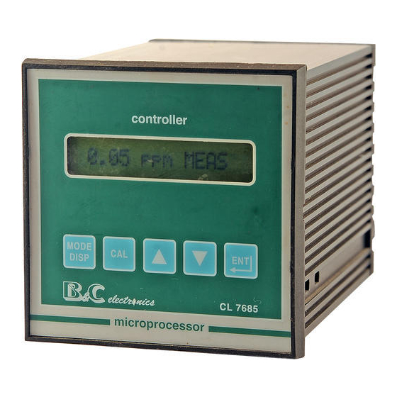
B&C Electronics CL 7685 9 PREVENTIVE MAINTENANCE Controller Quality components are used to give the controller a high reliability. The frequency of such maintenance depends on the nature of each particular application. As in any electronic equipment, the mechanical components, such as switches, relays and connectors, are the most subject to damage. - Page 42 B&C Electronics CL 7685 FRONT PANEL Display Mode-display key Calibration key Increase key Decrease key Enter key Fig. 1 – Operator’s Manual - Rev. C - 05/05...
- Page 43 B&C Electronics CL 7685 REAR PANEL CONNECTIONS 1. 2 110 V power supply 1. 3 220 V power supply Ground (power) 5. 6 A relay N.O. contacts 6. 7 A relay N.C. contacts 8. 9 B relay N.O. contacts 9. 10 B relay N.C.
- Page 44 B&C Electronics CL 7685 DIMENSIONS AND DRILL PLAN (measures in mm) Fig. 3 – Operator’s Manual - Rev. C - 05/05...
- Page 45 B&C Electronics CL 7685 N O T E S – Operator’s Manual - Rev. C - 05/05...
Need help?
Do you have a question about the CL 7685 and is the answer not in the manual?
Questions and answers