
Related Manuals for B&C PH 7687


Summary of Contents for B&C PH 7687
- Page 1 Instruction manual PH 7687 pH/ORP CONTROLLER Option REP N° Power supply: 85 ÷ 264 Vac Installed firmware: R 1.0x Cod. 28001766 - Rev A...
-
Page 3: Table Of Contents
PH 7687 INDEX INDEX 1 – GENERAL WARNINGS AND INFORMATION FOR ALL USERS 1.1 Warranty ..................3 1.2 After sales service ................3 1.3 CE marking .................. 3 1.4 Safety warnings ................4 1.5 Manual revisions ................4 2 – PRODUCT OVERVIEW 2.1 Functional purpose of the device ............ - Page 4 PH 7687 INDEX 6 – OPERATING PROCEDURE 6.1 Operating principles ............... 27 6.2 Display ..................28 6.3 Keyboard ..................28 6.4 Users instruction ................29 6.4.1 Main measure ..............29 6.4.2 Secondary measuring ............29 6.4.3 Analog output 1 values ............30 6.4.4...
-
Page 5: General Warnings And Information For All Users
PH 7687 GENERAL WARNINGS AND INFORMATION FOR ALL USERS GENERAL WARNINGS AND INFORMATION FOR ALL USERS WARRANTY This product is guaranteed for 5 years from the date of purchase for all manufacturing defects. Please take a look at the terms and conditions described on the warranty certificate at the end of the manual. -
Page 6: Safety Warnings
PH 7687 GENERAL WARNINGS AND INFORMATION FOR ALL USERS SAFETY WARNINGS It is important to underline the fact that electronic instruments are subject to acciden- tal failure. For this, it is important to take all necessary precautions to avoid damages caused by malfunctions. -
Page 7: Product Overview
PH 7687 PRODUCT OVERVIEW PRODUCT OVERVIEW FUNCTIONAL PURPOSE OF THE DEVICE The system for monitoring pH and ORP consists of two main parts: • the meter/regulator described in this instruction manual; • a probe/measuring electrode. The instrument contains the electronic circuitry and firmware to perform the following functions: •... -
Page 8: Instruction Manual Contents
PH 7687 INSTRUCTION MANUAL CONTENTS INSTRUCTION MANUAL CONTENTS This chapter describes the manual and gives suggestions to all users on how to read it and use it. The manual is written according to the following norms: • UNI 10893 "Instructions for use";... -
Page 9: Using The Instrument On The Plant
PH 7687 INSTRUCTION MANUAL CONTENTS The user normally can read the values on the display. He will read the parts of the manual regarding the: - "Users instruction (page 29)". Maintenance staff could be more interesting in the chapters re- garding: - "Users instruction (page 29)";... -
Page 10: Instrument Installation
PH 7687 INSTRUCTION MANUAL CONTENTS – band, integration and derivative time, actuation on the set point (PID opera- tion) – minimum and maximum alarm values – delay on alarm – activation/deactivation of the logic inputs – on/off function of automatic or manual sensor cleaning –... -
Page 11: Specifications And Technical Data
PH 7687 SPECIFICATIONS AND TECHNICAL DATA SPECIFICATIONS AND TECHNICAL DATA FUNCTIONAL SPECIFICATION Display The instrument is equipped with a graphic display that shows the values of the measures and messages to the operator in the various stages of use of the unit. - Page 12 PH 7687 SPECIFICATIONS AND TECHNICAL DATA When using the PID action, the display shows the status of actuation. Thanks to the specific front panel keys SET1 and SET2, setting the set point value is very simple. A password can be set in order to avoid that other users may change the settings.
- Page 13 PH 7687 SPECIFICATIONS AND TECHNICAL DATA • enable or disable the automatic/manual cleaning function; • set the interval of time between two cleaning cycles; • set the cleaning time; • set the holding time of measurement after cleaning. During the cleaning and holding time the instrument retains the last value on the analog output, while the set points and alarm relays are disabled.
- Page 14 PH 7687 SPECIFICATIONS AND TECHNICAL DATA Option low voltage 9 ÷ 36 Vdc or 12 ÷ 24 Vac The installation of this option allows you to use either a DC power supply from 9 to 36 V or an AC voltage from 12 to 24 V, 50-60 Hz.
-
Page 15: Technical Data
PH 7687 SPECIFICATIONS AND TECHNICAL DATA TECHNICAL DATA 4.2.1 GENERAL SPECIFICATIONS Precision 0.2 % Ripetibility 0.1 % Non linearity 0.1 % Alphanumeric display LCD 128 x 64 pixel Keyboard 4 keys Operating temperature -10 ÷ 60 °C Humidity 95 % without condensate Power supply 85 ÷... -
Page 16: Technical Specifications
PH 7687 SPECIFICATIONS AND TECHNICAL DATA 4.2.2 TECHNICAL SPECIFICATIONS In the left column is indicated the number of the display concerning: - SETUP parameters are indicated by "S xy" - CONFIGURATION parameters are indicated by "C xy" x = paragraph, y = sequential 1..2..3..4..ecc Default D1.0... - Page 17 PH 7687 SPECIFICATIONS AND TECHNICAL DATA Default D1.0 MAIN MEASURE Over range 2100 mV Filter software C1.3 Response time at 90 % large signal 0.4 ÷ 50.0 seconds 2.0 s C1.4 Response time at 90 % small signal 0.4 ÷ 50.0 seconds 10.0 s...
- Page 18 PH 7687 SPECIFICATIONS AND TECHNICAL DATA Default SET POINT 1 S3.1B • Proportional band 0.0 ÷ 400.0 % 1.0 % S3.2B • Integral time 0.0 ÷ 999.9 minutes 0.0 min S3.2B • Derivative time 0.0 ÷ 999.9 minutes (0=disabl.) 0.0 min C3.3...
- Page 19 PH 7687 SPECIFICATIONS AND TECHNICAL DATA Default SET POINT 2 C3.6 • Function LO / HI (Min / Max) FM regulation on relay 2 S3.8B • Pulse frequency 0 ÷ 120 pulses/minute 100 i/min • Pulse length 0.1 seconds WM regulation on relay 2 S3.8B...
- Page 20 PH 7687 SPECIFICATIONS AND TECHNICAL DATA Default D5.1 ANALOG OUTPUT 1 Under / Over range (4-20) 3.50 / 20.50 mA C5.3 Point 1 (0 mA o 4 mA) (pH) 0.00 ÷ 14.00 pH 0.00 pH C5.4 Point 2 (20 mA) (pH) 0.00 ÷...
- Page 21 PH 7687 SPECIFICATIONS AND TECHNICAL DATA Default LOGIC INPUT (D1 and D2) ALARM condition • Analog output • Set point • Alarm status S6.1 Logic input 1 ON / OFF C6.1 Function of the logic input 1 HOLD / ALARM HOLD S6.2...
- Page 22 PH 7687 SPECIFICATIONS AND TECHNICAL DATA Default D50.0 SETUP S3.4B Pulse width WM SET1 0 ÷ 99.9 seconds 20.0 s S3.5A Hysteresis SET2 (ON-OFF) 0.00 ÷ 1.40 pH 0.02 pH S3.6A Delay SET2 (ON-OFF) 0.0 ÷ 100.0 seconds 0.2 s S3.5B...
- Page 23 PH 7687 SPECIFICATIONS AND TECHNICAL DATA Default D60.0 CONFIGURATION C4.2 SET1 operation time 0 ÷ 60 minutes 60 min C4.3 Alarm related to SET2 operation ON / OFF time C4.4 SET2 operation time 0 ÷ 60 minutes 60 min C4.5...
-
Page 24: Installation
PH 7687 INSTALLATION INSTALLATION PACKING LIST The package contains: • N° 1 unit with serial number label; • N° 1 instruction manual. PACKING AND UNPACKING Open the carton box and keep it. Remove the instrument for the carton box. Remove the plastic protection from the instrument. -
Page 25: Electrical Installation
PH 7687 INSTALLATION In case of extension cable use high isolation IP 65 junction box (for example the acces- sory SZ 740). Keep the coax cable of the sensor away from the power cables. ELECTRICAL INSTALLATION For all the electrical connections refer to the label on the instruments, also shown and described in the chapter "Installation drawings (page 43)". -
Page 26: Connecting The Temperature Sensor
PH 7687 INSTALLATION • Connect the central of the coaxial cable to the electrode terminal 17 high imped- ance marked HI. • Connect the shield of the coaxial cable to the electrode terminal 16 low imped- ance marked LO. Use only the original coax cables supplied by the manufacturer in between sensor and input terminals of the instrument. -
Page 27: Connecting Pumps, Solenoids And Alarms
PH 7687 INSTALLATION If the output signal must drive more devices, they must be connected in "series" be- tween them. The sum of their input resistance must not be greater than 600 Ω. Alternatively the outputs can be used for PID control, and connected to actuators ac- cepting analog current signals (the connections are analogous to what reported for re- corders and PLC). -
Page 28: Connecting The Logic Inputs
PH 7687 INSTALLATION The alarm condition occurs when: • the measure exceeds the selected min/max values; • the operating time of set point 1 and 2 is exceed (if configurated); • contact from logic input 1 and 2 (if configurated). -
Page 29: Operating Procedure
PH 7687 OPERATING PROCEDURE OPERATING PROCEDURE OPERATING PRINCIPLES In the case of pH measurement the instrument receives a signal in mV from the sensor and provides the value in pH units, according to the Nernst's law. In the case of ORP measurement the instrument receives a mV signal from the sensor and provides the value in mV. -
Page 30: Display
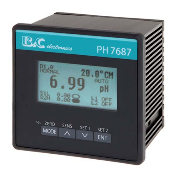
PH 7687 OPERATING PROCEDURE DISPLAY Display ID Information display (set points and analog inputs status; functions and messages) Secondary display Main display Operating mode Instrument status: NORMAL, CLEAN, HOLD, ALARM (MEAS/S1/S2/L1/L2) Main measuring unit KEYBOARD KEYS FUNCTION - To visualize the available displays - To exit from the not confirmed calibrations sequences - >3 s To access the zero calibration... -
Page 31: Users Instruction
PH 7687 OPERATING PROCEDURE USERS INSTRUCTION 6.4.1 MAIN MEASURE The display shows the measured value and allows access to the calibration procedures and set point values, if these were not reserved to the maintenance staff. If the user has enabled the cleaning function, during the cleaning cycle will show the value of the measure and the cleaning phase in progress: CLEAN or HOLD. -
Page 32: Analog Output 1 Values
PH 7687 OPERATING PROCEDURE 6.4.3 ANALOG OUTPUT 1 VALUES Press MODE two times from the display D1.0 to visualize the output signal and the cor- responding current value. 6.4.4 ANALOG OUTPUT 2 VALUES Press MODE three times from the display D1.0 to visualize the output signal and the cor- responding current value. -
Page 33: Parameters For The Maintenance
PH 7687 OPERATING PROCEDURE 6.4.6 PARAMETERS FOR THE MAINTENANCE Press MODE five times from the display D1.0 to visualize the SETUP display to access to the maintenance menu of the unit. 6.4.7 PARAMETERS FOR THE PLANT ENGINEER Press MODE six times from the display D1.0 to visualize the CONFIGURATION display to access to the installation menu of the unit. -
Page 34: Maintenance Instructions
PH 7687 OPERATING PROCEDURE Display Contents Meaning Possible values I1.0 P/N e firmware release B&C electronics PH7687 R1.00 I2.0 Screen brightness 0 ÷ 30 LCD BRIGHTNESS I3.0 Screen contrast 0 ÷ 30 LCD CONTRAST I4.0 Type of visualization of the screen... -
Page 35: Ph Calibration
PH 7687 OPERATING PROCEDURE 6.5.3 PH CALIBRATION Before calibration (also called electrodes standardization), check that the glass mem- brane of the sensor was kept moist during storage. If the protective reservoir is empty and the glass membrane is dry, immerse the elec- trode in a buffer solution or in tap water (do not use distilled water) for at least three hours before proceeding. - Page 36 PH 7687 OPERATING PROCEDURE Sensitivity calibration Place the electrode in solution at pH = 4 (SZ 952) or pH = 9 (SZ 956) to calibrate the 2nd point (Calibration of sensitivity). Press UP (SENS) for at least 3 seconds to get the following display:...
-
Page 37: Orp Calibration
PH 7687 OPERATING PROCEDURE The calibration of the pH meter in case of temperature compensation requires special precautions: • consider the value of pH of the buffer at the operating temperature; • detect the value of the temperature of the solution;... - Page 38 PH 7687 OPERATING PROCEDURE Sensitivity calibration (only if necessary) If the sensitivity calibration is necessary, place the electrode in the second standard so- lution. Press UP (SENS) for at least 3 seconds to get the following display: UP and DOWN...
-
Page 39: Temperature Calibration
PH 7687 OPERATING PROCEDURE 6.5.5 TEMPERATURE CALIBRATION Temperature sensor connected Place the sensor in a liquid or keep the sensor in the air knowing the value of the tem- perature. MODE press the key from D1.0 display to go to D2.0 display... -
Page 40: Setup
PH 7687 OPERATING PROCEDURE 6.5.7 SETUP Press MODE five times from the D1.0 display to go to the D50.0 display. press to display and confirm the sequence of the setup parameter of the unite UP and DOWN press to change the displayed value MODE press to turn to the D50.0 display any time... -
Page 41: Maintenance
PH 7687 OPERATING PROCEDURE Display Contents Meaning Possible values S3.5A Hysteresis of the set point 2 Selectable HYSTERESIS SET2 0.02 pH S3.6A Delay of the set point 2 0.0 ÷ 99.0 s SET2 DELAY 0.2 s S3.5B Proportional band of the set point 2 in 0.0 ÷... -
Page 42: Sensors Maintenance
PH 7687 OPERATING PROCEDURE Disconnect the power supply to the unit before performing the fol- lowing: - dust removal from the terminals; - operations on the wires connecting the terminals; - mounting of the instrument on the switch board panel. - Page 43 PH 7687 OPERATING PROCEDURE press the key to visualize and to confirm in sequence the configuration parameters UP or DOWN press the key to modify the values MODE press the key to turn to the D60.0 display any time Depending on the configuration of the instrument, few configura- tion parameters may not be visualized.
- Page 44 PH 7687 OPERATING PROCEDURE Display Contents Meaning Possible values C3.5 PID regulation related to set point 2 ACTUATION SET2 OUT2 C3.6 Set point 2 function HI/LO SET2 FUNCTION C4.1 Alarm activation on set point 1 opera- ALARM SET1 tion time C4.2...
-
Page 45: Installation Drawings
PH 7687 INSTALLATION DRAWINGS INSTALLATION DRAWINGS CONNECTION DIAGRAM Terminal Function Terminal Function Power supply 85 ÷ 264 Vac 14 + Analog output 2 Power supply 85 ÷ 264 Vac 15 + Analog output 1 Ground - Common analog outputs NO Set point 1... -
Page 46: Dimensions
PH 7687 INSTALLATION DRAWINGS DIMENSIONS - 44 - Cod. 28001766 - Rev A... -
Page 47: Warranty
PH 7687 WARRANTY WARRANTY Your product is guaranteed for 5 years from the date of purchase, for failure due to manufacturing defects. The warranty is void in case of tampering or deterioration due to improper instal- lation or maintenance. The warranty covers only free repair at the laboratories of the manufacturer. - Page 48 PH 7687 REPAIRS INFORMATION SHEET for service repairs In the event of a fault, we recommend you contact our repair service, to photocopy and complete this information sheet to be attached to the product to be repaired. □ ESTIMATE □ REPAIR...
- Page 49 PH 7687 REPAIRS Cod. 28001766 - Rev A - 47 -...
- Page 50 PH 7687 REPAIRS - 48 - Cod. 28001766 - Rev A...
- Page 52 B&C Electronics s.r.l. – Via per Villanova 3 – 20866 Carnate (MB) – Italia Tel. +39 039 631 721 – Fax +39 039 607 6099 – bc@bc-electronics.it – www.bc-electronics.it...
Need help?
Do you have a question about the PH 7687 and is the answer not in the manual?
Questions and answers