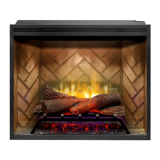
Dimplex RBF30 Service Manual
Hide thumbs
Also See for RBF30:
- Owner's manual (23 pages) ,
- Service manual (19 pages) ,
- Owner's manual (111 pages)
Table of Contents
Advertisement
IMPORTANT SAFETY INFORMATION: Always read this manual first before attempting to service this firebox. For your
safety, always comply with all warnings and safety instructions contained in this manual to prevent personal injury or prop-
erty damage.
Dimplex North America Limited
1367 Industrial Road Cambridge ON Canada N3H 4W3
1-888-346-7539 www.dimplex.com
In keeping with our policy of continuous product development, we reserve the right to make changes without notice.
© 2017 Dimplex North America Limited
Service Manual
Model
RBF30
RBF36
RBF36P
RBF42
Part Number
6909780100
6909790100
6909790200
6909800100
REV
PCN
DATE
00
-
12-JAN-17
7400970000R00
Advertisement
Table of Contents

Subscribe to Our Youtube Channel
Related Manuals for Dimplex RBF30


Summary of Contents for Dimplex RBF30
- Page 1 Dimplex North America Limited 1367 Industrial Road Cambridge ON Canada N3H 4W3 12-JAN-17 1-888-346-7539 www.dimplex.com In keeping with our policy of continuous product development, we reserve the right to make changes without notice. © 2017 Dimplex North America Limited 7400970000R00...
-
Page 2: Table Of Contents
NOTE: Procedures and techniques that are considered important enough to emphasize. CAUTION: Procedures and techniques which, if not carefully followed, will result in damage to the equipment. WARNING: Procedures and techniques which, if not carefully followed, will expose the user to the risk of fire, serious injury, or death. www.dimplex.com... -
Page 3: Operation
OPERATION Figure 3 Figure 1 Touch Panel and Remote Controls WARNING: The Revillusion Built-in Electric Firebox must be installed properly before it is used. CAUTION: Except for installation and cleaning described in this manual, an authorized service representative should perform any other servicing. The manual controls for the Revillusion Built-in Electric Firebox are located on the front panel. - Page 4 5 minutes before plugging the unit back in. CAUTION: If you need to con tinuously reset the heater, unplug the unit and call technical support at 1-888-346-7539. www.dimplex.com...
-
Page 5: Maintenance
MAINTENANCE General Maintenance Inspect the built-in electric firebox regularly, depending upon conditions, and at a minimum yearly intervals. Remove dust and clean the logs, grate, and base as required. WARNING: Disconnect power and allow heater to cool before attempting any maintenance or cleaning to reduce the risk of fire, electric shock, or injury. -
Page 6: Exploded Parts Diagram
16. Log Set Assembly RBF30 ....0442100100RP 11. Back log LED RBF30 ....3001760200RP... -
Page 7: Wiring Diagram
WIRING DIAGRAM... -
Page 8: Log Set Assembly Replacement
8. Re-assemble the remainder of the firebox in reverse 7. Re-assemble the unit in reverse order from the instruc- order from the instructions above. tions above. Figure 3 Flicker Motor Back Log Back Log Log Set Assembly Flame Panel Brackets Ember LED Light Flame Base LED www.dimplex.com... -
Page 9: Ember Led Light Replacement
EMBER LED LIGHT REPLACEMENT 4. On either side of the firebox gently remove the brick panels by placing you finger in the gap and pulling Tools Required: Philips head screwdriver forward. The brick panels are held in place by magnets Needle-nose pliers and need minimal force to be removed. -
Page 10: Flicker Motor Replacement
11. Disconnect the wire connectors, noting the location of 12. Re-assemble the remainder of the firebox in reverse the wires and connect the new motor wires. order from the instructions above. 12. Re-assemble the unit in reverse order from the instruc- www.dimplex.com... -
Page 11: Power Supply Replacement
Figure 4 Blower Cutout Element Assembly Main Control Board Power Supply Thermistor Hex Head Screws Main Control Assembly Top Front Lights 7. Disconnect the two main wire connectors - one on each WARNING: Ensure wires do not come in contact with side of the unit. -
Page 12: Element Replacement
11. Using a 3/8” ratchet or wrench remove the hex head screw from both sides of the element. Remove ele- ments from the element housing and replace with the new elements. www.dimplex.com... -
Page 13: Cutout Replacement
12. Re-assemble the remainder of the firebox in reverse 14. Re-assemble the remainder of the firebox in reverse order from the instructions above. order from the instructions above. WARNING: Ensure wires do not come in contact with WARNING: Ensure wires do not come in contact with moving parts by securing wires in wiring tie wraps. -
Page 14: Thermistor Replacement
10 minutes for the heating elements to cool off to avoid accidental burning of skin. WARNING: Disconnect power before attempting any maintenance to reduce the risk of electric shock or damage to persons. 1. Remove the front glass or any accessories that are www.dimplex.com... -
Page 15: Troubleshooting Guide
TROUBLESHOOTING GUIDE PROBLEM CAUSE SOLUTION General Circuit breaker trips or fuse Short in unit wiring. Trace wiring in unit. blows when unit is turned on Improper circuit current rating Additional appliances may exceed the current rating of the circuit breaker or fuse. Plug unit into another outlet or install unit on a dedicated 15 amp circuit. - Page 16 Loose wiring Trace wiring in unit Defective heater assembly Replace heater assembly Noise Excessive noise with the heater Dirty heater assembly Ensure that exterior intake louvers and firebox cavity are free of dirt/dust. Defective heater assembly Replace heater assembly www.dimplex.com...
Need help?
Do you have a question about the RBF30 and is the answer not in the manual?
Questions and answers