Table of Contents
Advertisement
Advertisement
Chapters
Table of Contents

Related Manuals for Protek 9216A


Summary of Contents for Protek 9216A
- Page 2 PROTEK 9216A Digital LCR Meter User’s Manual Volume 1: Basic Operation Rev. 3.0...
-
Page 3: Table Of Contents
Table of contents Introduction ................................4 Warranty................................. 4 General Safety Summary ..........................5 Preventing Injury ............................. 5 Preventing Instrument Damage ......................5 Maintenance, Repair, and Storage ....................5 Product Damage Prevention ......................6 Line Voltage Requirements ......................6 Fuse Requirements .......................... 6 Conventions Used in This Manual ......................... - Page 4 Default Setup ............................19 Changing, Storing, and Recalling Custom Setups ................20 Measurement Mode........................20 Frequency ............................20 Drive Voltage ..........................21 Bias ..............................22 Measurement Rate ......................... 24 Settling Time ..........................25 Triggering............................25 Store and Recall ..........................26 Range .............................
-
Page 5: Introduction
PROTEK shall pay for the return of the product to customer if the shipment is to a location within the country in which the PROTEK service center is located. The customer shall be responsible or paying all shipping charges, duties, taxes, and any other charges for products returned to any other locations. -
Page 6: General Safety Summary
PROTEK’s responsibility to repair or replace defective products is the sole and exclusive remedy provided to the customer for breach of this warranty. PROTEK and its vendors will not be liable for any indirect, special, incidental, or consequential damages irrespective of whether PROTEK or the vendor has advance notice of the possibility of such damages. -
Page 7: Product Damage Prevention
To avoid personal injury, do not remove the product covers. Do not operate the product without the covers properly installed. Two spare fuses are shipped with this equipment. In order to maintain this equipment in a stable and efficient operating condition, calibrate the equipment after every 1,000 hours operating time or every 6 months, whichever is shorter. -
Page 8: Conventions Used In This Manual
Shape (diameter length) mm Circuit No. Rating Remarks 5.2 20 F1101 250 V T500 mA For AC l15V 250 V T250 mA For AC 230 V 5.2 20 F601 250 V F250 mA The internal fuse rating is as follows: Shape (diameter ... -
Page 9: Product Familiarization
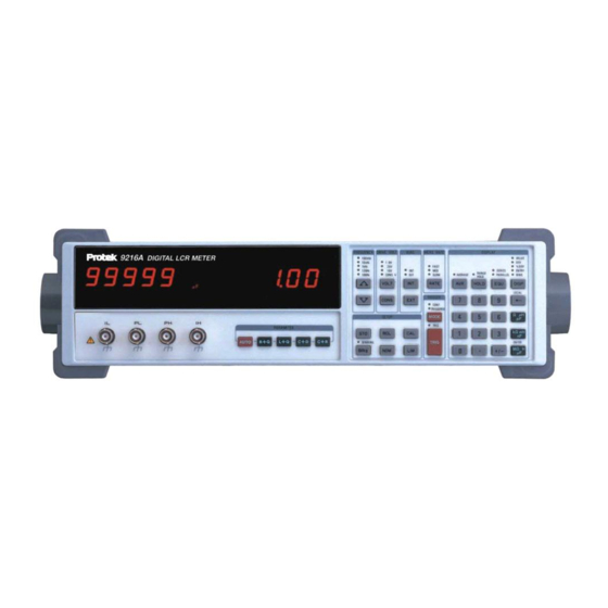
Chapter Product Familiarization Description of the LCR Meter and Its Features In this chapter, the controls and connections of the LCR Meter are described, and its basic operation is summarized in terms of the meter’s specifications, features and options, and operating modes. Front Panel Components The front panel and its displays, controls, and connections are shown in the following illustration:... -
Page 10: Alphanumeric Displays And Parameter Indicators
mode is indicated by LEDs above the alphanumeric displays. The operation of each mode can be explained as follows: AUTO In this mode, the meter automatically selects the most appropriate measurement on the device. The selection is made according to the following criteria: If |Q| <... -
Page 11: Programming And Operator Interface Keys
LED indicators associated with them show which option has been selected. Frequency The 9216A has five selectable fixed frequencies with an accuracy to 100ppm (0.01%). 100Hz, 120Hz, 1kHz, 10kHz or 100 kHz may be selected by pressing the up/down keys on the front panel keypad until its corresponding LED is illuminated. - Page 12 %. SETUP STO, RCL The 9216A can store up to nine setups in the memory. To store the present configuration in memory location #n, press STO [n] ENTER. To recall a setup, press RCL [n] CAL ENTER.
-
Page 13: Rear Panel Components
TRIGGER MODE This key toggles between continuous (CONT) or TRIGGERED measurements . TRIG When TRIGGER mode is selected, measurements are initiated when this key is pressed or by the handler or computer interfaces. The TRIG LED will flash when this mode is enabled. -
Page 14: Specifications
Specifications Display Measurement Modes: Auto, R+Q, L+Q, C+D, C+R Equivalent Circuit: Series or Parallel Parameters Displayed: Value, Deviation, % Deviation or Bin Number. Deviation and % deviation are calculated from a stored relative value Averaging: 2–10 Measurements ... -
Page 15: Features And Options
Accuracy Value R > 0.125 and R < 16 M better than 1% for L > 2.5 H and L < 25 kH C > 1.25 pF and C < 12.8 mF better than 5 % for R > 21 m and R < 96 M L >... -
Page 16: Options
Kelvin clips Provides connection to devices that are not easily accommodated by the test fixture. Polarity is indicated for biased measurements. SMD Tweezers Provides connection to surface mount components BNC fixture adapter Connects remote fixtures or devices to the 9216A... -
Page 17: Basic Operations
Basic Operations How the 9216A Operates and What It Can Do The 9216A LCR meter is very versatile in that the user can customize the measurement and operating modes to obtain the best results in a particular situation. In this chapter, the basics of the meter’s operation are summarized. -
Page 18: Startup Procedures
(standard), Kelvin clips, SMD tweezers, and BNC adapter. The optional fixtures may be purchased through our distributors. The standard 9216A test fixture attaches to the four input terminals on the front panel of the meter and provides two polarized, spring-loaded connection slots to secure radial-leaded components under test while they are being measured. -
Page 19: Null Calibration Procedure
DISP (Display) key. Changing Test Setup Parameter Settings When powered on, the 9216A LCR Meter initially uses the default test setup parameters, which include selection of the automatic (AUTO) measurement mode, and the result of the measurement is displayed on the alphanumeric readout. -
Page 20: Default Setup
See the sections that follow for more details on the settings listed in the table below. Table 1-1: 9216A default settings Setting Value... -
Page 21: Changing, Storing, And Recalling Custom Setups
Changing, Storing, and Recalling Custom Setups Measurement Mode The measurement mode is selected by pressing one of the four keys in the PARAMETER group of keys on the front panel. AUTO In this mode, the meter automatically selects the most appropriate measurement on the device. -
Page 22: Drive Voltage
Drive Voltage The 9216A meter has three fixed output rms voltages, 0.1 V, 0.25 V and 1.0 V. These voltages are selectable from the front panel. A variable rms voltage is also available, which is adjustable from 0.1 V to 1.0 V with 50 mV resolution. The accuracy of the voltage levels is 2% or greater. -
Page 23: Bias
Figure 3-1. Normalized Voltage Across DUT vs. DUT Impedance Bias Internal or external DC bias voltages can be applied to capacitors. Electrolytic and tantalum capacitors need a positive bias for accurate measurements, although the meter bipolar test voltage will not typically be enough to damage them. - Page 24 stabilize in a reasonable amount of time. See the section on the constant voltage mode for effects on ranges and accuracy. It will take a short while for the internal circuitry and the DUT to stabilize after applying the bias voltage. The time is primarily determined by the RC time constant of the source resistance and the capacitor under test, plus the internal AC coupling capacitor of 0.47 F.
-
Page 25: Measurement Rate
Measurement Rate The 9216A has three measurement rates, which are selected by pressing the Rate button. Slow, medium or fast rate may be selected. Table 3-2 lists the maximum measurement rates attainable when the meter is not in the auto-range mode, binning is disabled, and the RS232 interface is active. -
Page 26: Settling Time
If an illegal value is entered, the meter will beep and display “range error.” Triggering The 9216A can make measurements continuously or in response to a trigger. To change the trigger mode: 1. Press the MODE key in the TRIGGER group of front panel keys until the desired mode LED is on;... -
Page 27: Store And Recall
Note: When making a measurement, the meter will ignore any triggers it receives until the current measurement is complete. Store and Recall The STO and RCL buttons allow nine complete instrument setups to be saved in nonvolatile memory. All the test conditions, including binning, configuration and open short circuit compensation, are saved. - Page 28 Autoranging Mode During normal operations, the meter automatically changes to the most accurate range for the device under test. When the meter measures an impedance that is out of its current range, it goes up or down one range, and makes another measurement.
- Page 29 Constant Voltage (CONS) Mode Occasionally, a test will require using a specific drive voltage that is not possible using the normal source resistance for that measurement range. In these cases, press the CONS key and thereby set the source impedance to a fixed 25 . The voltage across the component under test will be almost constant for all devices with impedance substantially larger than 25.
-
Page 30: Series And Parallel Equivalent Circuits
Series and Parallel Equivalent Circuits Generally, as illustrated in Figure 3-2, any non-ideal component has a different value for a series or parallel equivalent circuit due to the characteristics of the component. The “quality” of an inductor is expressed by Q, the ratio of the reactive (inductive) part of its impedance to its resistive part. - Page 31 LED is lit. The Deviation display is not available in the AUTO mode and if no nominal value has been previously entered. To Enter a Nominal Value, 1. Press and release the DISP key until the ENTRY LED is lit. 2.
- Page 32 PROTEK 9216A Digital LCR Meter User’s Manual Volume 2: Reference Table of Contents Background on Components and Measurements ....................4 Definitions of Resistive and Reactive Parameters ..................4 Component Categories..........................4 Units ................................ 5 Series and Parallel Equivalent Circuits ......................5 Quality Factors ............................
- Page 33 L+Q Accuracy ..........................10 C+D Accuracy ..........................10 C+R Accuracy ..........................12 Accuracy When Holding a Nonoptimal Range ..................13 Verification of Meter Performance ........................ 14 Functional Tests ............................ 14 Necessary Equipment: ........................15 Front Panel Test ..........................15 Self Tests ............................15 Output Voltage ..........................
- Page 34 Nothing Happens at Turn-on ......................... 39 Reset Procedure ..........................39 Internal Fuse Check ........................39 External Bias Fuse Check....................... 39 Error Messages ............................40 Operational Errors ..........................40 Self-test Errors ............................40 Calibration Errors ........................... 42 RS-232 Problems ..........................42 9216A TEST PERFORMANCE RECORD....................44...
-
Page 35: Background On Components And Measurements
Background on Components and Measurements Properties of Resistors, Inductors, and Capacitors The measurements made by the 9216A Digital LCR Meter are based on the definitions of impedance and the properties of discrete components designed to provide impedances in electronic circuits. -
Page 36: Units
In this situation of positive, imaginary impedance, the impedance is purely inductive, as an ideal inductor would be. The impedance of an ideal inductor with inductance L is a jL. linear function of frequency, given by Z If the phase of the voltage is 90 degrees (/2 radians) behind the phase of the current, then the impedance is a negative imaginary number: ... -
Page 37: Quality Factors
Figure 1-1 Equivalent circuits for inductors and capacitors. The complex impedance of a capacitor is (series equivalent circuit) (9a) (parallel equivalent) (9b) Quality Factors Originally, the quality factor Q was defined for an inductor as a measure of the efficiency of energy storage in the inductor when an AC current is passed through it. - Page 38 Q C (12b) Using the quality factor, the impedance of an inductor is seen to be (13a) and the inductor’s series equivalent circuit components can be expressed in terms of its parallel equivalent circuit components as ...
-
Page 39: Accuracy And Calibration
Accuracy Specifications Note: The accuracy of the 9216A that is stated in this chapter is valid for the following conditions: (a) a warm-up time of at least 30 minutes, (b) a temperature of 23C 5C, (c) the use of the built-in fixture, and (d) the completion of the open and short circuit calibra- tions. - Page 40 Figure 2-1 Basic Impedance Accuracy Table 2-1 Integration Time Accuracy Factor, K Meas. Rate Frequency Slow, Medium 6.25 < Z Fast 100 Hz to 1 kHz < 400 k All other Table 2-2 Drive Voltage Error Factor, K Vout (Vrms) 0.55 to 1.0 1/Vout 0.3 to 0.5...
-
Page 41: Accuracy Equations For Specific Measurement Modes
Table 2-3 Extreme Range Error Terms, K and K Frequency 100 Hz, 120 Hz, 1 kHz (1 m/Z /2 G) 10 kHz (1 m/Z /1.5 G) 100 kHz (4 m/Z /50 M) Accuracy Equations for Specific Measurement Modes R + Q Accuracy In the R + Q measurement mode, the basic impedance accuracy A in the equation for impedance accuracy may be read from Figure 2-1 directly while interpreting the ―imped- ance‖... - Page 42 Figure 2-2 Basic Impedance Accuracy for Inductances Table 2-4 Extreme Range Error Terms for Inductances, K and K Frequency (1 H/L 100 Hz, 120 Hz /2.6 MH) (0.1 H/L 1 kHz /260 kH) (0.02 H/L 10 kHz /10 kH) (0.02 H/L 100 kHz /100 H) The accuracy of the capacitance measurement is calculated from equation (1) above,...
-
Page 43: C+R Accuracy
Figure 2-3 Basic Impedance Accuracy for Capacitances Table 2-5 Extreme Range Error Terms for Capacitances, K and K Frequency 100 Hz, 120 Hz (2 pF/C /1600 mF) 1 kHz (0.1 pF/C /160 mF) 10 kHz (0.01 pF/C /16 mF) /200 F) 100 kHz (0.02 pF/C C+R Accuracy... -
Page 44: Accuracy When Holding A Nonoptimal Range
Table 2-6 Extreme Range Error Terms for Capacitances (C + R mode), K and K Frequency 100 Hz, 120 Hz (2 pF/C /2000 mF) 1 kHz (0.1 pF/C /200 mF) 10 kHz (0.01 pF/C /10 mF) /100 F) 100 kHz (0.01 pF/C measurement is given by Accuracy of R in % [A... -
Page 45: Verification Of Meter Performance
The performance verification procedures in this section test and verify the performance of 9216A and compare it to the specifications listed in Volume 1 of this manual. The first set of tests verifies the basic functionality of the unit. The second set of tests verifies the criti- cal specifications of the 9216A. -
Page 46: Necessary Equipment
6. The unit must be switched off to leave this mode. Self Tests The internal self tests verify the functionality of the 9216A. Turn on the unit. The ROM program and model name will be displayed for about three seconds. Next the message "tESt..' will be displayed while the unit performs its self tests. -
Page 47: Resistance Measurement
1. Set the 9216A to 1 kHz, 1 V and constant voltage. Set the scope to 1 V/div verti- cal and 0.5 ms/div horizontal. Connect a 10 probe to the scope. 2. Place the tip of the probe into the "+" side of the fixture and connect the ground clip to the center guard. -
Page 48: Performance Tests
1.25%. D values should be below 0.001 for 10 kHz and 0.01 for 100 kHz. Performance Tests These tests are intended to measure the 9216A's conformance with its published specifications. These test results, along with the results of the functional tests, can be recorded on the test sheet at the end of this manual. -
Page 49: Impedance Accuracy
2. Set the 9216A to its default conditions by pressing the key sequence RCL 0 EN- TER. Set the unit to constant voltage mode. The output voltage should be 1.0 Vrms at 1 kHz. Verify that the voltage reading is between 0.98 and 1.02 Vrms. - Page 50 Connect the IL and PL leads to the "" terminal of the decade capacitor box. Set the 9216A to its default conditions by pressing the key sequence RCL 0 EN- TER, then select the R+Q measurement mode and the 1 kHz test frequency.
-
Page 51: Calibration Procedures
To set the jumper, re- move the 9216A top cover by removing its four retaining screws (this will break the calibration seal). In the rear center of the circuit board is a three pin jumper labeled JP1001. -
Page 52: Calbytes
Recalibration of the 9216A involves determining new values of the calbytes and storing them in the RAM. The calbyte values that are determined at the time of the 9216A manu- facture are also stored in ROM and may be recalled at any time. The standard resistor calbytes are automatically determined by the standard resistor calibration subroutines. -
Page 53: Necessary Equipment And Conditions
DVM. Do not connect either end to ground. Set the meter to AC volts, auto ranging. Set the 9216A to its default conditions by pressing the keys, RCL 0 ENTER. Set the unit to constant voltage mode. -
Page 54: Frequency Calibration
The clock correction factor is stored in parts per million (ppm). 1. Set the 9216A to its default conditions by pressing the keys RCL 0 ENTER. Set the unit to constant voltage mode at 1 kHz, and remove any part from the fixture. -
Page 55: Standard Resistor Calibration
In addition, the 9216A and the calibration resistors must be placed in a temperature controlled room and allowed to sta- bilize at least 30 minutes before attempting calibrate. - Page 56 6. Check the standards at different frequencies. Use the series equivalent for the two smaller resistors and the parallel equivalent for the two larger ones. R should remain relatively constant and Q should scale with frequency (i.e. Q at 10kHz is 10 ...
-
Page 57: Remote Control Of The Lcr Meter
The 9216A LCR meter may be controlled and programmed remotely using either an RS232 Any computer supporting either of these interfaces may be used with the 9216A. Both interfaces are simultaneously active and are accessed via the connectors on the rear panel. -
Page 58: Setting Up To Use The Rs-232 Interface
CTS/DTR hardware handshaking discussed above. The CTS signal (pin 8) is an output of the meter indicating that the 9216A is ready, while the DTR signal (pin 4) is an input to the meter that is used to control the 9216A transmissions. If desired, the handshake pins may be ignored and a simple three-wire interface (pins 2, 3 and 5) may be used. - Page 59 The present value of a particular parameter may be determined by querying the 9216A for its value. A query is formed by appending a question mark "?" to the com- mand mnemonic and omitting the desired parameter from the command. If multiple...
-
Page 60: List Of Commands
Table 3-5 Examples of Command Formats FREQ 2 <LF> Sets the drive frequency to 100 Hz (one-parameter command) FREQ ? <LF> Queries the drive frequency (query of one-parameter command Sets the upper limit of bin 3 to 1000 (three-parameter command BLIM 0, 3, 100 <LF>... -
Page 61: Status Displays And Error Messages
The REM LED is lit whenever the 9216A is in a remote state (front panel locked out). The 9216A reports two types of errors that may occur during command execution: command errors and execution errors. -
Page 62: Definitions Of Status Bytes
Definitions of Status Bytes Serial Polling name usage Ready The 9216A is ready to perform a measurement Not used Not used An unmasked bit in the LCR status register has been set. An unmasked bit in the standard status byte has been set. -
Page 63: Measurement
Measurement name usage Math Error Set on a floating point error. A/D Error Set when an A/D conversion fails. Overload Set when the gain stage is overloaded. Under range Set when a measurement is below the nominal range of values for the present range Over range Set when a measurement is below the nominal range of values for the present... -
Page 64: Binning
Binning Using the LCR Meter to Sort Components The 9216A has built in features to aid in component sorting, which is useful for production testing, incoming inspection, device matching, or tests in which multiple components of similar value must be measured. The binning feature simplifies parts sorting by eliminat- ing the need to read the major and minor parameters and then deciding what to do with the part. -
Page 65: Sequential Bins With Different Nominal Values
Nominal value 4% 3% 2% 1% 1% 2% 3% 4% Bin 0 Bin 1 Bin 2 Bin 3 Figure 4-1 Example of Nested Bins Sequential Bins With Different Nominal Values Suppose that the batch of nominally 100 resistors is to be sorted according to actual value instead of according to tolerance, as in the previous example. -
Page 66: General Procedures
Bin 2 Bin 3 Bin 4 Bin 0 Bin 1 98 100 102 104 106 1% 1% 1% 1% 1% Figure 4-2 Example of Sequential Bins With Different Nominal Values Nominal value Bin 0 Bin 1 Bin 2 Bin 3 Bin 4 5% 3%... -
Page 67: Setting Up The Bins
Setting Up the Bins Procedures Initial Setup To enter binning information the unit cannot be in the AUTO parameter mode. Make cer- tain that the unit is set to the correct measurement mode (R+Q, L+Q, C+D or C+R). Press the BIN# key, which will bring up the bin entry display and put the unit in the entry mode. -
Page 68: Enable Binning
Enable Binning To enable or disable binning, press the BIN# key until the ―Sort Off‖ or ―Sort On‖ mes- sage appears. Pressing the ENTER key from this display toggles binning (sorting) on and off. When binning is enabled, the BINNING LED is on, the BINS display is active, and the handler interface (if installed) is active. -
Page 69: Summary Of Binning Setups
Summary of Binning Setups Pass/Fail Setup Enter the nominal value and limits for Bin 0. Enter the QDR fail value for Bin 8. Make sure no other bins are open (set their limits to zero). Parts that pass fall into Bin 0; and all other parts fall into Bin 8 or Bin 9. -
Page 70: Troubleshooting
Chapter Troubleshooting Hints for Solving Problems In this chapter, suggestions are given for solving common troubleshooting problems General Problems Nothing Happens at Turn-on Make sure that the power entry module on the rear panel is set for the AC line voltage for your region, that the correct fuse is installed, and that the line cord is inserted all the way into the power entry module. -
Page 71: Error Messages
Error Messages The following lists explain all of the error messages that the 9216A can generate. The messages are divided into operational errors (errors in using the instrument), self-test er- rors, and calibration errors. The messages are listed alphabetically. - Page 72 Code Err XX The 9216A ROM has a checksum error. XX is the checksum value. CPU Error The 9216A has detected a problem in its CPU.
-
Page 73: Calibration Errors
Make sure that the RS-232 baud rate, parity, and word size are set to match that ex- pected by the controlling computer. The default settings are 1200 baud, no parity, 8 bit data. The 9216A always sends two stop bits, and will correctly receive data sent with ei- ther one or two stop bits. -
Page 74: 9216A Test Performance Record
9216A TEST PERFORMANCE RECORD Serial #: Date: Tested by: Equipment used:... - Page 75 FUNCTIONAL TESTS Pass Fail Front Panel Test Self Test Drive Voltage 24.9 Resistance Test 400 6.4 k 100 k Capacitance Test FREQUENCY ACCURACY Test Frequency Minimum Actual Maximum 100 Hz 99.99 Hz 100.01 Hz 120 Hz 119.99 Hz 120.01 Hz 1 kHz 999.90 Hz...
- Page 76 RESISTANCE ACCURACY Resistance Range Conditions Value Pass Fail 10.0 1 kHz, series 25.0 1 kHz, series 25.0 10 kHz, series 25.0 100 kHz, series 100.0 1 kHz, series 100.0 1 kHz, series 400.0 1 kHz, series 400.0 10 kHz, series 400.0 100 kHz, series 1.6000 k...
Need help?
Do you have a question about the 9216A and is the answer not in the manual?
Questions and answers